DOI: 10.4236/ojapr.2018.64008 Dec. 20, 2018 84 Open Journal of Antennas and Propagation
Department of Electrical Engineering, University of Chile, Santiago, Chile
Abstract
A simple design method for electromagnetic wave absorbers under normal incidence is presented. For the fabrication of the microwave absorbing ma-terial a novel design chart is used, including curves of constant δ δe m ratio in a
(
δe+δ ε µm, ′ ′)
plane. The practical use of the chart is explained and, asexample, a microwave absorber fabricated with magnetite-impregnated plas-tisol is designed and tested at X-band frequencies.
Keywords
Permittivity, Permeability, Single Layer, Microwave Absorption, Reflection Loss
1. Introduction
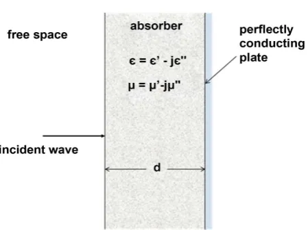
The single-layer homogeneous absorber (SLHA) backed by a perfectly conduct-ing plate, known also as the Dallenbach layer, has been the subject of several in-vestigations in the last decades due to its practical importance [1]-[9]. According to Figure 1, the design parameters for the SLHA are: ε′, ε′′, µ′, µ′′ and
0
d λ . These parameters must satisfy the zero reflection condition which occurs when the surface impedance of the structure becomes identical to that of free space. In order to simplify the design process, graphical aids have been presented providing also a view of the interrelated numerical values of material parameters required to meet the perfect matching condition at the design frequency [1]-[9].
All design theories for SLHA compute the reflection coefficient at the inter-face, usually in terms of the input impedance at the absorbing layer. The general solution for the perfect SLHA was found by defining the electric loss angle
(
)
arctan
e
δ = ε ε′′ ′ and the magnetic loss angle δm =arctan
(
µ µ′′ ′)
asinde-pendent variables to present the zero reflection condition in the (δe, δm) plane How to cite this paper: Jacard, B.,
Valen-zuela, A. and Gonzalez, M. (2018) Practical Universal Method for Designing Single-Layer Electromagnetic Wave Absorbers. Open Journal of Antennas and Propagation, 6, 84-92.
https://doi.org/10.4236/ojapr.2018.64008
Received: October 6, 2018 Accepted: December 17, 2018 Published: December 20, 2018
Copyright © 2018 by authors and Scientific Research Publishing Inc. This work is licensed under the Creative Commons Attribution International License (CC BY 4.0).
DOI: 10.4236/ojapr.2018.64008 85 Open Journal of Antennas and Propagation
Figure 1. Homogeneous layer absorber.
[3]. Within this original approach, the first design condition that the input im-pedance is real, fixes the electric thickness of the layer. Finally, the condition that the input impedance is equal to the intrinsic impedance of free space yields the µ ε′ ′ ratio required for perfect absorption. This general solution was further developed and extended to calculate previously unavailable universal design curves and design equations for different orders of solutions [8].
Using the same theoretical approach employed to obtain general solutions [3] [8], in this paper we present a novel universal design chart for the SLHA where instead of curves of constant µ ε′ ′ ratio in the loss plane (δm, δe), curves of constant δe/δm ratio in the
(
δe+δ ε µm, ′ ′)
plane are presented.Absorbers are usually fabricated by impregnating a dielectric binder with a lossy filler; the main contribution of this work is to facilitate the design of the SLHA, by providing a graphical aid that shows when the optimum filler to bind-er ratio that gives pbind-erfect absorption has been achieved. Anothbind-er contribution is the successful use and measurements of natural magnetite-impregnated plastisol as microwave absorbing material since the electromagnetic characteristics and the use of this composite at X-band frequencies seemingly have not been re-ported in the literature.
This paper is organized as follows: Section 2 provides the theoretical approach for developing a universal design chart for the SLHA. Section 3 explains the prac-tical use of the chart for designing a microwave absorber. As a pracprac-tical demon-stration of this novel design procedure, an absorber fabricated with a composite material made of magnetite-impregnated plastisol is designed and tested at X-band frequencies; the main results are presented and discussed. Section 4 summarizes the main conclusions of this work.
2. Theory
The material of the SLHA is characterized by a thickness d and complex relative electromagnetic parameters ε ε= −′ jε′′=ε′
(
1−jtanδe)
and(
1 tan m)
DOI: 10.4236/ojapr.2018.64008 86 Open Journal of Antennas and Propagation (binder and filler composite) can be plotted as a single point, whereas the former plane is suitable only for representing ideal absorbing conditions.
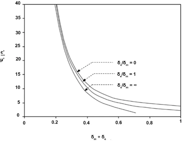
Using Equations (1) and (2), the universal design chart of Figure 2 has been produced. The chart contains curves for the two extreme cases of zero electric loss (δe/δm = 0) and zero magnetic loss (δe/δm = ∞). No solutions can be found outside the band defined by the two extreme cases, the range of total loss (δe+ δm) for perfect absorption is relatively narrow, especially for high ε µ′ ′ ratio. The intermediate condition of equal electric and magnetic loss angles (δe/δm = 1) is also presented for reference purposes.
These design curves are exact provided that the conditions of Figure 1 prevail, i.e. no gap between the absorber and the perfectly conducting plate. A particular design curve could be drawn for any intermediate value of δe/δm. However, this is not necessary when ε′µ′ since all solutions (δe+ δm) for total absorption will lie in a narrow band.
Microwave absorbing materials are usually prepared by blending a lossy filler in powder (e.g. carbon black, aluminum, iron, magnetite, ferrites) with a dielec-tric binder (e.g. epoxy resin, silicon rubber, plastics). These materials are cha-racterized by a complex permittivity and permeability. When increasing the fil-ler/dielectric ratio (maintaining constant frequency), the ε′, δe and δm values increase [10] [11] [12] [13] [14]. Therefore, the corresponding points for the candidate absorber composites in the
(
δe+δ ε µm, ′ ′)
plane of Figure 2 willoutline a curve with positive slope that intersects the appropriate design curve on the chart, thus helping to determine the optimum filler concentration for the absorbing material. The design of the SLHA is completed specifying the material thickness d. For this purpose the following approximate solution of Equation (2) can be obtained [3][8]:
(
)
(
)
0 0
cos cos cos
sinh cosh 1
1
4 1 cosh 4 cos
2
m m e
m e
r s s s
d
rs s
δ δ δ
π π π π
θ λ
λ π λ π π µ ε δ δ
− −
= =
+
′ ′ + (3)
DOI: 10.4236/ojapr.2018.64008 87 Open Journal of Antennas and Propagation
Figure 2. Universal design chart for SLHA.
When the loss angles are small, Equation (3) simplifies to the well-known quar-ter wavelength approximation d=λ 4.
3. Results and Discussion
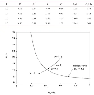
The design method will be illustrated using a composite made of magne-tite-impregnated plastisol. The binder is a PVC emulsion and plasticizer com-pound. The filler is natural magnetite in powder sieved under 325 mesh (44 μm). The components are blended according to a previously specified magne-tite/plastisol weight ratio p. The homogeneous paste is then heated in a 180˚C oven for about 20 minutes, allowing the solidification of plastisol. The resulting rubber-like material is flexible and molded samples can be easily cut and thinned as necessary.
DOI: 10.4236/ojapr.2018.64008 88 Open Journal of Antennas and Propagation
Figure 3. Representation of magnetite-plastisol composites (p = 1, 1.7, 2, 3) in the design chart at 9.8 GHz.
parameters of this composite are included in Table 1 and in Figure 3 it is ob-served that the corresponding point is sufficiently close to the design curve making unnecessary the fabrication of composites with other intermediate mag-netite/plastisol ratios.
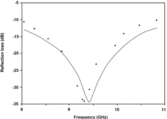
The SLHA was fabricated with a layer of magnetite-impregnated plastisol of weight ratio p = 1.7 and thickness d = 2.1 mm (according to the design value predicted by Equation (3)), glued to a 20 × 20 cm aluminum plate. The reflection loss measured as a function of frequency in the X-band is shown in Figure 4. It is observed that the highest absorption is obtained at 9.35 GHz instead of the de-sign frequency (i.e. 9.8 GHz). This frequency shift is a consequence of not con-sidering so far the existence of an adhesive layer between the absorber and the metallic plate. This dielectric layer, although thin, in practice has an important influence in the optimum absorption frequency. On the other hand, the influ-ence of the finite conductivity of the aluminum plate is negligible.
[image:5.595.208.533.85.416.2]DOI: 10.4236/ojapr.2018.64008 89 Open Journal of Antennas and Propagation
Figure 4. Absorption characteristics of the magnetite-plastisol composite (p = 1.7, d = 2.1 mm, g = 0.1 mm). ▲▲▲ measured. ̶ ̶̶̶̶̶̶ calculated.
Figure 5. Permeability of the magnetite-plastisol composite (p = 1.7) against frequency.
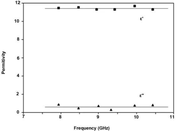
From the data included in Figure 5 and Figure 6, the following linear regres-sions are obtained:
0.045 1.425
µ′ = − ⋅ +f (4)
0.055 0.955
µ′′ = − ⋅ +f (5)
0.004 f 11.407
ε ′ = − ⋅ + (6)
0.008 f 0.615
ε ′′ = − ⋅ + (7)
In Equations (4)-(7) f is the frequency in GHz.
Using these expressions and considering now an adhesive layer of thickness g
[image:6.595.233.514.329.528.2]DOI: 10.4236/ojapr.2018.64008 90 Open Journal of Antennas and Propagation
Figure 6. Permittivity of the magnetite-plastisol composite (p = 1.7) against frequency.
characteristics of the two-layer structure was obtained (considering normal in-cidence of plane waves). As shown in Figure 4, good agreement between the calculated and measured values for the absorption is obtained. Consequently, in order to refine the SLHA design, the effective thickness of the absorbing material should be calculated subtracting the thickness of the adhesive layer to the value of d given by Equation (3). With this procedure, maximum absorption will be obtained, approximately, at the design frequency.
In Figure 4 it is also observed that the experimental relative bandwidth of the designed SLHA is about 10% and 30% for −20 dB and −10 dB reflection loss, re-spectively.
4. Conclusions
A universal design method for designing single-layer electromagnetic wave absor-bers under normal incidence has been presented. The method is based on a novel design chart which includes curves of constant δe/δm ratio in a
(
δe+δ ε µm, ′ ′)
plane. When representing the electromagnetic characteristics of composite ab-sorbing materials in the design chart, it is observed that the corresponding points are very sensitive to the lossy filler concentration. Therefore, the optimum con-centration at a fixed frequency is easily found after representing the measured parameters of a few trial materials with different concentrations in the design chart. Once the optimum absorbing material has been determined, the optimum thickness of the SLHA is readily calculated using a simple expression. The me-thod has been successfully applied for designing a high performance microwave absorber using a low cost composite material made of magnetite-impregnated plastisol.
DOI: 10.4236/ojapr.2018.64008 91 Open Journal of Antennas and Propagation curves there presented show all the possible optimum parameter combinations required for perfect absorption, but do not show how far from optimum absorp-tion is a candidate absorber, whereas the general design chart presented in this work graphically displays when a particular candidate absorber is near or will actually achieve the optimum parameter combination.
The key difference with [9] is that the particular design curves (valid only for specific values of the parameters) there presented show the optimum thickness for maximum absorption, assuming that imperfect absorption is the rule, whe-reas the general design chart presented in this work shows that any particular candidate absorber can achieve perfect absorption if the optimum mixture of binder and filler is provided. Once this optimum mixture is achieved a general equation gives the optimum thickness, so no curves are necessary for this pur-pose.
Acknowledgements
This work has been funded by the University of Chile and FONDECYT Project N˚1940439.
Conflicts of Interest
The authors declare no conflicts of interest regarding the publication of this pa-per.
References
[1] Naito, Y. and Suetake, K. (1971) Application of Ferrite to Electromagnetic Wave Absorber and Its Characteristics. IEEE Transactions on Microwave Theory and Techniques, 19, 65-72. https://doi.org/10.1109/TMTT.1971.1127446
[2] Knott, E.F. (1979) The Thickness Criterion for Single-Layer Radar Absorbents.
IEEE Transactions on Antennas and Propagation, 27, 698-701.
https://doi.org/10.1109/TAP.1979.1142149
[3] Fernandez, A. and Valenzuela, A. (1985) General Solution for Single Layer Electro-magnetic-Wave Absorber. Electronics Letters, 21, 20-21.
https://doi.org/10.1049/el:19850016
[4] Hartemann, P. and Labeyrie, M. (1987) Absorbants d’ondes électromagnétiques.
Revue Technique Thomson-CSF, 19, 413-472.
[5] Musal, H.M. and Hahn, H.T. (1989) Thin-Layer Electromagnetic Absorber Design.
IEEE Transactions on Magnetics, 25, 3851-3853. https://doi.org/10.1109/20.42454
[6] Musal, H.M. and Smith, D.C. (1990) Universal Design Chart for Specular Absor-bers. IEEE Transactions on Magnetics, 26, 1462-1464.
https://doi.org/10.1109/20.104411
[7] Han, K.C., Kim, W.S. and Kim, K.Y. (1995) Practical Design Method for an Elec-tromagnetic Wave Absorber at 9.45 GHz. IEEE Transactions on Magnetics, 31, 2285-2289. https://doi.org/10.1109/20.376231
DOI: 10.4236/ojapr.2018.64008 92 Open Journal of Antennas and Propagation
[13] Kong, I., et al. (2010) Magnetic and Microwave Absorbing Properties of Magne-tite-Thermoplastic Natural Rubber Nanocomposites. Journal of Magnetism and Magnetic Materials, 322, 3401-3409. https://doi.org/10.1016/j.jmmm.2010.06.036
[14] Guan, B., et al. (2017) The Electromagnetic Wave Absorbing Properties of Ce-ment-Based Composites Using Natural Magnetite Powders as Absorber. Materials Research Express, 4, Article ID: 056103.