ISSN Online: 2151-4844 ISSN Print: 2151-481X
DOI: 10.4236/sgre.2017.88018 Aug. 21, 2017 265 Smart Grid and Renewable Energy
Performance Assessment of a Calm Flapping
Wind Turbine with Small Attack Angle
Md. Sabbir Alam
1, Hiroyuki Hirahara
21Graduate School of Science and Engineering, Saitama University, Saitama, Japan 2Faculty of Engineering, Saitama University, Saitama, Japan
Abstract
The objective of this research is mainly focused on environment-friendly and moderately slow flapping wind turbine which can easily operate in or near urban areas or rooftops owing to scale merit with low-frequency turbine noise, installation cost, avian mortality rate and safety consideration etc. The authors are focusing on lift based (LB) slow flapping wind turbine operated within a small attack angle amplitude whereas the previous research treated a lift and drag based (LDB) flapping turbine. Here, a unique trajectory for the wing motion was yet designed by using the Chebyshev dyad linkage mechan-ism as well as the previous report. The wind energy transferred to the mechani-cal rotation, adopting a single symmetric wing NACA0012. To obtain a smooth flapping motion for the blade, we optimize all fundamental parameters with our simulation model for optimum performance of the turbine. Both static and dynamic analysis has been conducted to confirm the feasibility of the present design. In addition, wind turbine performance was studied for a suitable range of free stream wind velocities. This report confirms that the developed flap-ping wind turbine can drive at slow speed with suitable energy extraction rate at different wind velocities. Moreover, we made a simple comparative study of the outcomes obtained from our previous lift and drag based flapping wind turbine with present one, i.e., lift based flapping turbine.
Keywords
Flapping Turbine, Chebyshev-Dyad Linkage, Angle of Attack, Unique Trajectory, Torque
1. Introduction
Facing the future challenge in energy demands, renewable energy is considered as the main source of sustainable energy. An interest in utilizing renewable energy is
How to cite this paper: Alam, M.S. and Hirahara, H. (2017) Performance Assess-ment of a Calm Flapping Wind Turbine with Small Attack Angle. Smart Grid and Renewable Energy, 8, 265-290.
https://doi.org/10.4236/sgre.2017.88018
Received: July 18, 2017 Accepted: August 18, 2017 Published: August 21, 2017
Copyright © 2017 by authors and Scientific Research Publishing Inc. This work is licensed under the Creative Commons Attribution International License (CC BY 4.0).
http://creativecommons.org/licenses/by/4.0/
DOI: 10.4236/sgre.2017.88018 266 Smart Grid and Renewable Energy
growing rapidly owing to several factors such as cost-competitiveness, energy security, environmental concerns, growing demand for energy in developing countries and emerging economies with the need for access to modern energy. In 2015, an estimated of 147 GW renewable power capacity was added, which is the largest amount ever [1].
Wind energy is considered as a viable renewable source of green energy for a sustainable environment. Natural energy of “wind” in the wind power is con-verted into electrical energy without any of the CO2 emissions. In addition, the produced energy easily adds into the grid of the building with reduction of its external energy demand [2]. A new Carbon Trust study [3] showed that small wind turbines could generate up to 1.5 Terawatt of electricity per year which can reduce a huge amount of CO2 emission annually. Therefore, global environmental issues are the main concern for researchers that is expected to continue expan-sion in the future. The traditional concept of converting wind energy to generate electricity is based on the Horizontal axes wind turbine (HAWT) and vertical axes wind turbine (VAWT). However, VAWT is not economically attractive as HAWT, though they offer energy solution for the remote area [4]. VAWT shows advantage compares to HAWT since these kinds of mechanics do not suffer from the frequent wind direction change and are suitable for structural and aesthetical reasons. Moreover, VAWT shows improved power in turbulent flows which is typical in built environment [5]. Development of micro-windmill, as an alternate source of energy, is increasing rapidly, to be utilized in the place where is close to the residential area or the rooftops. Safety is an important fact to operate wind turbine near the residential area. However, the wind turbine provides clean re-newable energy but it has also some complications. Solving noise annoyance generated by the wind turbine is one of the important technical issues for the development of wind turbine used in the place where is close to the residential arena [6]. Also, mitigate the bird and bat mortalities caused by turbines is an area of research to be improved [7] [8]. Moreover, to utilize the hill effect in the residen-tial arena, researchers are now focusing on the development and utilization of rooftop wind turbine [5].
DOI: 10.4236/sgre.2017.88018 267 Smart Grid and Renewable Energy
(NAVs) [11] [12] [13]. The characteristics of flapping wing aerodynamics de-pend on wing geometry, wing structural properties, flow condition and the kine-matics of wing motion. As it’s a complicated task to understand flapping wing aerodynamics due to the leading-edge vortex, span wise flow and delayed stall phe-nomena, many researchers demonstrate “trial and error” approaches for flapping wing MAV [12]. These analyses on the flapping wing suggested that its mechan-ism has a universal advantage for low cost and sustainable energy resource in nat-ural ecology.
On the other hand, to install wind turbine near residential area or rooftop, it is always an important issue to ensure structural stability, noise annoyance and slow rotating speed in terms of safety consideration. Slow flapping type VAWT is an innovative idea to resolve such unwanted problem as it can provide the predictable amount of energy. Considering all these facts, we proposed such a slow flapping type wind turbine. The flapping blade motion is controlled by vari-ous geometrical parameters for a given wind velocity and produced unsteady lift and drag forces by the wing and therefore works effectively for generating rota-tional torque. In our present research, we optimize the turbine design to create a suitable trajectory for flapping motion by the wing blade. To optimize the de-sign, we emphasize on a combination of all parameters like link length, deltoid angle, mounting angle, the amount of generated torque and working ability of turbine. In flapping motion, the aerofoil’s angle of attack continuously changes which resulting in the change of circulation around the aerofoil [11]. The dy-namic stall is one of the key parameters that debilitates the turbine efficiencies. A stall occurs due to the flow separation when turbine blade changes its position with large attack angle, once that happened the blade lift force is affected and drops significantly with overall energy extraction efficiency. To ride off this aerodynamic behaviour of aerofoil we consider small attack angle amplitude in our present flapping wind turbine design. In this paper, a numerical investiga-tion carried out with the main objective is to design and develop a lift dominat-ing flappdominat-ing turbine fabricated with Chebyshev-dyad link mechanism to extract wind energy. Present turbine design considered as an alternative solution name-ly lift based (LB-type) relative to our previous turbine design, which was designed as lift and drag based (LDB-type) [14]. Moreover, implementation of a slower flapping wind turbine for practical use has been demonstrated focusing on usage near housing area or on rooftops due to less noise annoyance with a reasonable amount of power extraction. As far as the authors aware of, applying flapping wing concept for extracting wind energy is generally a new field to develop and no substantial research has been conducted yet.
2. Mechanism of Flapping Wind Turbine
con-DOI: 10.4236/sgre.2017.88018 268 Smart Grid and Renewable Energy
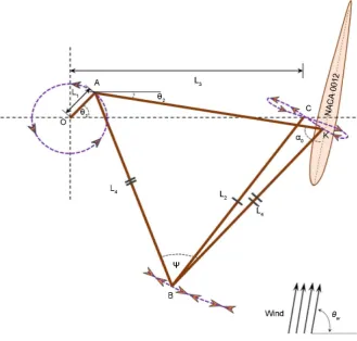
trolled by various geometrical parameters for a certain wind speed. In our pro-posed flapping wind turbine with Chebyshev-dyad link mechanism by which the symmetric wing, NACA0012 can transfer the wind energy to mechanical rota-tion through a unique morota-tion. As shown in Figure 1, the wing blade is con-nected to the rotor by Chebyshev-dyad linkage and the wind force is converted to rotating motion via this link mechanism. Therefore, linkage mechanism plays an important role in the mechanical arena to drive the generated forces as well as to transfer the forces in different output motions [15] [16]. To confirm stability in performance, applicability with high operation speed and high load bearing capabilities, it is important to confirm the suitable combination of these linkage geometrical parameters [17] [18]. The link length ratio, L1:L2:L3:L4; the blade mounting angle, α0; and the deltoid angle, ψ are the important controlled
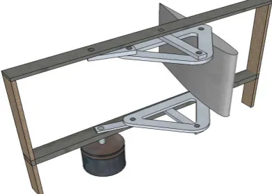
[image:4.595.208.538.400.714.2]parameters for the movement of the flapping wind turbine. In general, Cheby-shev-dyad link mechanism has the advantage of transforming mechanical forces by a symmetric curve to another symmetric one. For example, using Chebyshev- dyad linkage a symmetric 4-bar coupler curve can easily convert as a circular path [19]. A unique “figure eight” trajectory considered as an input curve of Chebyshev- dyad and the output curve identifies as a circular curve in our present system. Figure 2 shows the schematic view of flapping wind turbine. For present system, a set of two linkages supports a single blade, NACA0012 mounted normal to the flow direction.
DOI: 10.4236/sgre.2017.88018 269 Smart Grid and Renewable Energy
Figure 2. Flapping wind turbine schematics.
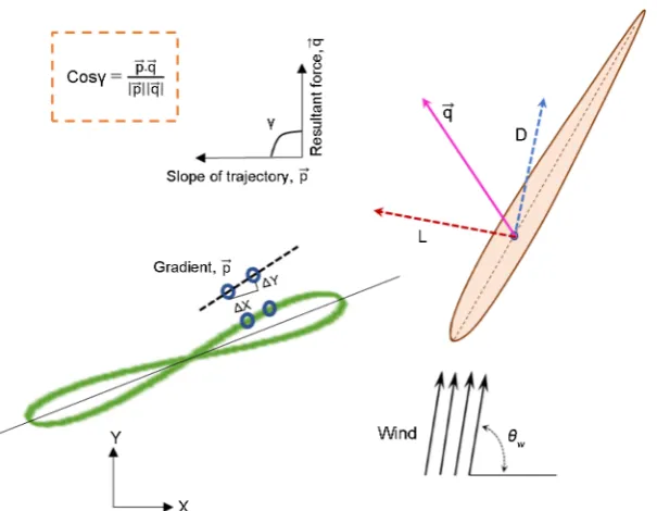
In the flapping design, the blade fixed on a predetermined point with the con-stant mounting angle and the wing blade moves through the unique trajectory, i.e. the wing fixed at point K in Figure 1 moves through the figure eight trajec-tory in the cycle. The point-A draws a rotational motion and point-B draws a rocking motion which is associated with the movement of the wing blade. Therefore, with the movement of the wing blade along the trajectory, the angle of attack changes continuously. The attack angle variation at different wing posi-tions for a static wind speed directly affected the aerodynamic forces generated by the wing blade. Once the flapping turbine is in motion, the generated aero-dynamic forces by the wing blade convert as rotor rotational motion through the Chebyshev-dyad linkage. Due to the periodic movement of the wind turbine, even though the flow is uniform the relative velocity of the wing blade and flow direction varies in each cycle. A rapid change of attack angle beyond the stall condition and flow separation occurs due to the large angle of attack. Though a large angle of attack inevitably appears in a certain region, in this circumstance the wing enters in a stall but maintains a large lift and drag coefficients, by de-signing a suitable trajectory for the turbine we can get an effective driving force [14]. The stall is an unsteady phenomenon and difficult to approximate the tur-bine performance accurately under the stall condition. Therefore, in our present turbine design, we overlook the stall phenomenon owing to large attack angle in motion by focusing on a slow flapping wind turbine operated within a small at-tack angle amplitude, i.e. lift based flapping wind turbine. The wind direction angle, θw is considered 90˚ and the rotor rotation is an anti-clockwise direction for the present system. Aerofoil’s chord length and wing span are select as 0.2 m and 0.3 m respectively for present study (Figure 3).
3. Mechanical Analysis
DOI: 10.4236/sgre.2017.88018 270 Smart Grid and Renewable Energy
Figure 3. The inner product between resultant force and the blade trajectories.
though the flow is uniform, the relative velocity of the wind blade and flow di-rection varies during a cycle. Therefore, the aerodynamic force coefficient de-pends directly on the angle of attack with the relative flow velocity. The Rey-nolds number considered for the flow velocity from 5 m/s to 12 m/s varies with-in a range of 6.6 × 10⁴ to 2.0 × 10⁵. The Reynolds number in the present system for the wind velocity of 10 m/s is close to the value of 1.6 × 10⁵ considered in the literature [21].
According to the geometrical relation shown in Figure 1, putting O as origin, the corresponding coordinates of points A x y
(
1, 1)
, B x y(
2, 2)
, C x y(
3, 3)
, and Point K x y(
4, 4)
were given in similar way as described in the previous paper [14].The angle of attack of the wing is determined using the following relation with the mounting angle, α0 and the wind angle, θw:
0 2
w
α θ= −α θ− (1) In the present system, the resultant force act in the rotational direction and work as the main driving force through an eight-shaped trajectory. Through the link mechanism, air flow converts to a rotatory motion which rotates a generator connected by a vertical shaft for power generation. Lift and drag forces are calcu-lated as:
2
1 2 L
L= C ρbcU (2)
2
1 2 D
D= C ρbcU (3)
DOI: 10.4236/sgre.2017.88018 271 Smart Grid and Renewable Energy
similar our previous flapping wind turbine [14] to evaluate the torque generated by the rotatory motion [17] [18]. The generated torque was determined by solv-ing all equations of equilibrium with the lift and drag force as described in the next equation.
(
)
(
) (
{
)
(
)
}
(
)
(
) (
{
)
(
)
}
3 4 1 5 1 5
1 2
3 1 4 1 1 3 4 3 1 4 3 4
3 4 1 5 1 5
1 2
3 1 4 1 1 3 4 3 1 4 3 4
y y D x x L y y
T x x D
x y x y x y x y x y x y
x x D x x L y y
y y L
x y x y x y x y x y x y
− − + − = − + − − + + − ⋅ ⋅ ⋅ ⋅ ⋅ ⋅ − − + − + − − − − + + − ⋅ ⋅ ⋅ ⋅ ⋅ ⋅ (4)
The rotational angular velocity of the rotor was calculated by solving the fol-lowing equation of motion for a rigid body by using an explicit fourth order Runge-Kutta method. d d I T t ω = (5)
where I represent the inertia moment for the rotating disk with radius (r) which was assumed by summing up predicted masses (M) as the generator and shaft, etc. to make it a more practical application for different load conditions.
2
4
r
I= M (6)
When the turbine is in motion, the relative velocity is calculated with wing velocity as follows:
(
)
2(
)
20cos w kx 0sin w ky
U= V
θ
−V + Vθ
−V (7)The rotor speed is variable in our present system, therefore the wing velocity calculated as indicated in the next equations.
1 d i i K K Kx x x V t + −
= (8)
1 d i i K K Ky y y V t + −
= (9)
The relative inlet angle is calculated as follows
1 0 tan Kx Ky V V V
φ= −
−
(10)
Here, the number i represents the calculational nodal number.
There are several key parameters related to wind turbine which can quantify the turbine performance under certain situation. In general, wind flow can har-ness mechanical energy through rotating a wind turbine by blades. The mechan-ical energy can convert to electric energy through a generator. The reference wind power for incoming wind can be evaluated as
3 0
1 2 w
P = ρAV (11)
DOI: 10.4236/sgre.2017.88018 272 Smart Grid and Renewable Energy
power for wind turbine is defined as
m
P = ⋅T ω (12)
The power coefficient, Cp is determined as Equation (13) with a
dimension-less form, for which the theoretical maximum value is known as Betz’s coeffi-cient as 0.593.
3 0 1 2 p T C AV ω ρ ⋅
= (13)
4. Optimization Procedures
In the present system, there exists many parameters, it is hard to use single for-mulation procedure for all engineering design problem due to the variation of objectives and constraints in the design problem [22] [23] [24]. In optimization approach, we have to focus on the primary objective of the optimization. Here, we need to address the variables influencing the optimization problem. Since some sort of parameterization is required, we at first seek a set of input parame-ters which can fully characterize the problem. The parameparame-ters are considered as an important factor in design, if the variation of the parameter may affect signif-icantly the performance measure of the problem. Moreover, it must be kept in mind that the complexity of an optimization increasing exponentially with the number of parameters, thus the number of variables needs to be minimum as much as possible [25]. In the mechanical design with an optimization process, designers always consider certain objectives such as strength, weight, output measure, lifetime etc. However, design optimization for a complete mechanical assembly leads to a complicated objective function with many design variables. So, it is always a good practice to apply optimization techniques for individual components or intermediate design than a complete design [26]. In the practical design problems, the number of design parameters is very large in general and their influences on the objectives function may be complicated owing to nonli-near characteristics. However, the objective functions have many local extrema, but, designers always interested in global extremum under certain region.
DOI: 10.4236/sgre.2017.88018 273 Smart Grid and Renewable Energy
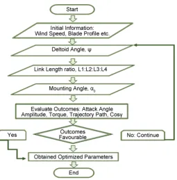
Figure 4. Parameters optimization flowchart for optimal design pro-cedure.
overall working ability, the amount of generated torque, and slow flapping mo-tion. To evaluate the designed turbine performance, the simulation has been conducted using our developed MATLAB code.
5. Static Simulation
DOI: 10.4236/sgre.2017.88018 274 Smart Grid and Renewable Energy
Figure 5. Variation of trajectory by the wing blade for different deltoid angle.
ψ = 55˚ ψ = 60˚
[image:10.595.59.540.372.704.2]DOI: 10.4236/sgre.2017.88018 275 Smart Grid and Renewable Energy
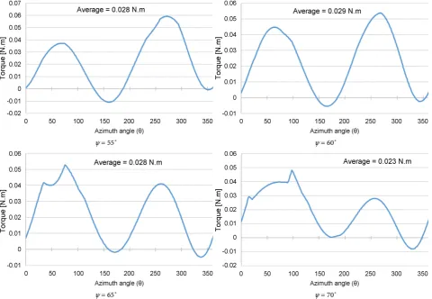
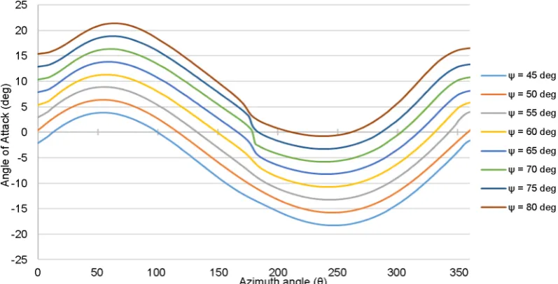
Figure 7. Variation of angle of attack in one complete rotation of the wing for different deltoid angle.
Figure 8. Average cosine value obtained for one complete rotation with different deltoid angle, ψ.
comparing with other position and maintain small attack angle amplitude for the wing in motion.
[image:11.595.171.537.307.496.2]DOI: 10.4236/sgre.2017.88018 276 Smart Grid and Renewable Energy
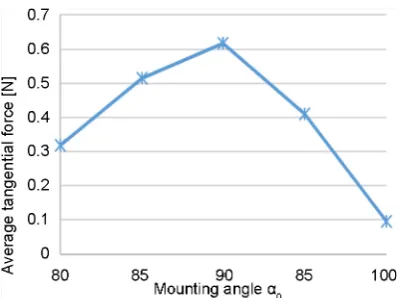
Figure 9. Average tangential force for varying mount-ing angle at a wind speed of 5 m/s.
Figure 10. Variation of angle of attack by the wing blade for different mount-ing angle.
Therefore, we approval the optimum mounting angle as 90˚ for the present de-sign, so it provides the maximum tangential force with suitable attack angle am-plitude in turbine motion.
[image:12.595.232.515.257.442.2]DOI: 10.4236/sgre.2017.88018 277 Smart Grid and Renewable Energy
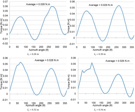
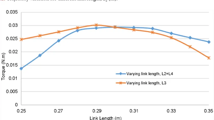
example of varying link length L2 with other fixed parameters: link lengths L1 equals to 0.05 m, L3 equals to 0.3 m, deltoid angle equals to 60˚ and the wind ve-locity 5 m/s; this gives the variation of torque curves shown in Figure 11 with av-erage torque values. Figure 12 shows the different trajectories generated by the wing blade for different link length, L2. A small variation of the link length L2 makes the torque curve variation with the trajectory and the trajectory variation influences the angle of attack curves as well as the overall performance of the wind turbine. Figure 13 shows a summary of the average torque values simu-lated for different link lengths L2, L3 and L4 with the individual linear change to obtain maximum torque. In each case, the variation of one link length with the other link length fixed as 0.3 m. Also, Figure 14 shows a relation of the average cosine value for the link length L2, L3 and L4 with linear change for the same cri-teria. Therefore, small differences in link length L2 and L3 considered as a favor-able neighboring region for the design and same values of these two-link lengths provide enhanced results in terms of trajectory shape, average torque value, av-erage cosine value and small attack angle amplitude for one complete rotation.
The preferable values obtained by static analysis for the present wind turbine are the link length ratio (L1:L2:L3:L4) as 0.05:0.3:0.3:0.3; the deltoid angle, ψ is 60˚;
L2 = 0.28 m L2 = 0.30 m
[image:13.595.108.540.350.707.2]L2 = 0.32 m L2 = 0.34 m
DOI: 10.4236/sgre.2017.88018 278 Smart Grid and Renewable Energy
Figure 12. Trajectory variation for different link length, L2 (m).
Figure 13. Average torque value curve based on varying link lengths, L2, L3 and L4.
DOI: 10.4236/sgre.2017.88018 279 Smart Grid and Renewable Energy
Figure 14. Average cosine value curve based on varying link lengths, L2, L3 and L4.
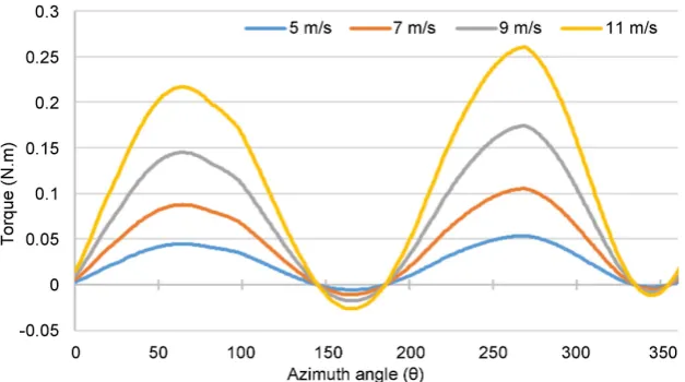
Figure 15. Static torque development for one rotation with different wind speeds.
6. Dynamic Simulation
To estimate more practical approximations for the present wind turbine, dy-namic analysis has been conducted with the optimum parameters based on the static analysis. In this simulation, the motion of equation was solved with rela-tive velocity details were discussed in Section 3. Figure 16 shows the generated torque obtained from the dynamic motion of the wind turbine at three different wind speeds 5 m/s, 7 m/s, and 9 m/s. The dynamic simulation started from θ1 = 0 and from the rest state. The increment angle was taken as 0.01 degrees. Figure 16 shows the dynamic torque during 5 seconds after the motion start. In the dy-namic simulation, the turbine is accelerated in some duration and approaches to equilibrium rotation speed.
[image:15.595.218.532.275.450.2]DOI: 10.4236/sgre.2017.88018 280 Smart Grid and Renewable Energy
Figure 16. Transient torque at different wind velocities up to 5 s.
Figure 17. Development of angular velocities for different wind speeds with respect to time.
motion, the generated torque is spent for the generation of motion. To achieve quasi-steady motion become faster with the increasing of wind velocities. In Figure 17, we assumed torque distributed function Φ = Φ(90%_10%), i.e., the turbine load as ninety percent of the generated torque under three different wind velocities, which used for the counterbalance of load generated by the generator and rest of the torque used for the motion continuation. Figure 18 shows the developed angular velocity at wind speed 5 m/s under three different load condi-tions.
7. Comparison of Static and Dynamic Torques
[image:16.595.229.522.273.442.2]DOI: 10.4236/sgre.2017.88018 281 Smart Grid and Renewable Energy
Figure 18. Development of angular velocities with respect to time under differ-ent torque distribution at wind speed 5 m/s.
lower in the first half cycle but little bit upper in the second half relative to the static torque curve. Of course, the difference is attributed to the relative velocity owe to the blade rotation.
8. Power Coefficient
The dynamic analysis gives a perception of the new flapping wind turbine per-formance. As the generated torque varies with rotation angle, the generated power shows the fluctuation, so the power coefficient curves also vary depending on the rotation angle. Figure 20(a) represent the power developed by the wind turbines up to first 10 s starting from rest state and Figure 20(b) represent the power de-veloped by the wind turbines for 5 s when the turbine performance reached in quasi-steady rotation speed at wind speed 7 m/s with torque distributed function Φ = Φ(90%_10%). Similarly, Figure 21(a) represent the power developed by the wind turbines for first 10 s and Figure 21(b) represent the power developed by the wind turbines for 5 s when the turbine performance reached in quasi-steady state at wind speed 7 m/s with torque distribution function Φ = Φ(80%_20%). As more torque is used for the motion continuation, the angular velocity of the wind turbine increases with time which has a direct influence on turbine per-formances. Figure 22 represents the average developed power by the wind tur-bine with a wide range of variation in wind speed.
DOI: 10.4236/sgre.2017.88018 282 Smart Grid and Renewable Energy
Figure 19. Comparison of static and dynamic torques for three different wind velocities 5, 7, and 9 m/s respectively.
DOI: 10.4236/sgre.2017.88018 283 Smart Grid and Renewable Energy
[image:19.595.84.536.61.261.2](a) Φ = Φ(90%_10%) (b) Φ = Φ(90%_10%) Figure 20. Power curve with time at wind speed 7 m/s.
[image:19.595.75.543.116.717.2](a) Φ = Φ(80%_20%) (b) Φ = Φ(80%_20%) Figure 21. Power curve with time at wind speed 7 m/s.
[image:19.595.88.538.292.507.2]DOI: 10.4236/sgre.2017.88018 284 Smart Grid and Renewable Energy
[image:20.595.90.534.64.271.2] [image:20.595.91.535.301.495.2](a) Φ = Φ(90%_10%) (b) Φ = Φ(80%_20%) Figure 23. Power coefficient curve with time at wind speed 7 m/s.
[image:20.595.62.542.495.704.2](a) Φ = Φ(90%_10%) (b) Φ = Φ(80%_20%) Figure 24. Power coefficient curve with time at wind speed 7 m/s.
DOI: 10.4236/sgre.2017.88018 285 Smart Grid and Renewable Energy
9. Comparison with LB-Type and LDB-Type
The characteristic performances obtained for the static case at wind velocity 5 m/s of the lift based flapping wind turbine has been compared with our pre-viously designed flapping wind turbine [14]. The attack angle variation at dif-ferent wing positions for a fixed wind speed directly affected the aerodynamic forces generated by the wing; Figure 26(a) represents the angle of attack variation by the wing blade for one complete rotation. In Figure 27(a) and Figure 27(b) shows the lift and drag forces generated from the wind by the flapping wing blade for one complete rotation. In Figure 27(a), the lift curve in the present turbine is smoother compared to previous one and generated a negligible amount of drag force whereas the previous design shows a high gradient in the first half of the wing blade rotation as shown in Figure 27(b). The developed
[image:21.595.60.535.269.466.2](a) (b)
Figure 26. (a) Comparison of angle of attack variation for one complete rotation; (b) Comparison of torque curves for one com-plete rotation at wind speed 5 m/s.
(a) (b)
[image:21.595.61.542.510.691.2]DOI: 10.4236/sgre.2017.88018 286 Smart Grid and Renewable Energy
static torque curved for one complete rotation has been compared in Figure 26(b), the average torque value is 0. 030 N·m at 5 m/s wind speed for our new lift based flapping wind turbine which is tiny low compared to our previous lift and drag based flapping turbine at similar wind speed. In the new design, the torque curve for one rotation of the wind turbine is quite smooth compared to previous design which is considered as one of advantage in our new turbine’s performance.
The dynamic performance obtained from lift based flapping wind turbine also compared with our previously designed lift and drag based flapping wind tur-bine. We consider two different cases: 1) Φ = Φ(90%_10%), i.e., 90% of gener-ated torque developed in dynamic motion consumed to counterbalance the load generated by the generator and remaining torque used for the motion continua-tion; and 2) Φ = Φ(80%_20%), i.e., 80% of generated torque developed in dy-namic motion consumed to counterbalance the load generated by the generator and remaining torque used for the motion continuation. Figure 28(a) and Fig-ure 28(b) represents the angular velocity comparison at a wind speed of 5 m/s. Figure 29 represents the power curve comparison for present turbine design with previously designed wind turbine at a wide range of wind velocity. In each wind speed, we found that LB-type flapping wind turbine provides more average power compared to previous designed flapping wind turbine for same torque distribution in dynamic motion. Similarly, Figure 30 represents the power coef-ficient curves comparison for LB-type design and LDB-type design at a wide range of wind velocity. We consider both cases as same as for power curves. Also for variation in wind speed, we notice that LB-type flapping wind turbine pro-vide more average power coefficient compare to previously designed flapping wind turbine for same torque distribution in dynamic motion. In conclusion, the new lift based flapping wind turbine can be considered as a good alternate of our previously designed lift and drag based flapping wind turbine.
[image:22.595.91.536.496.707.2]DOI: 10.4236/sgre.2017.88018 287 Smart Grid and Renewable Energy
[image:23.595.88.537.60.261.2] [image:23.595.89.538.294.494.2](a) Φ = Φ(90%_10%) (b) Φ = Φ(80%_20%) Figure 29. Comparison of power developed by turbine for different wind velocities.
(a) Φ = Φ(90%_10%) (b) Φ = Φ(80%_20%) Figure 30. Comparison of power coefficient for different wind velocities.
10. Conclusions
A flapping type wind turbine operated with a small attack angle amplitude has been demonstrated in this report. The proposed wind turbine rotates along with “figure eight” trajectory, which was fabricated by Chebyshev-dyad linkage. In this report, we designed “lift-based” (LB-type) flapping turbine, comparing with the previous “lift-drag based type” (LDB-type).
DOI: 10.4236/sgre.2017.88018 288 Smart Grid and Renewable Energy
generate a high amount of torque with a smooth flapping motion by the wing blade moving through a unique figure-eight trajectory and maintain small attack angle amplitude. Both static and dynamic numerical analyses were conducted to estimate the characteristics behavior of the wind turbine for different wind ve-locities. The developed torque obtained from the static analysis was compared with the dynamic torque for one complete rotation of the rotor and makes a good agreement indeed.
The flapping wind turbine utilizes the generated force by the single wing blade effectively to convert a decent amount of mechanical power in a slow speed. More-over, the amount of generated average power, as well as average power coeffi-cient for flapping wind turbine operated within small attack angle shows the large gradient in comparison with LDB-type wind turbine. In addition, the pow-er production of LB-type can increase by extending the length and the width of the blade. Furthermore, the shape and size of the flapping wind turbine are possible to increase for more power generation depending on the region of tur-bine installation without affecting the objectives of the wind turtur-bine.
References
[1] Sawin, J.L., Seyboth, K. and Sverrisson, F. (2016) Renewables 2016 Global Status Report.
http://www.ren21.net/wp-content/uploads/2016/05/GSR_2016_Full_Report_lowres. pdf
[2] Bahaj, A.S., Myers, L., and James, P.A.B. (2007) Urban Energy Generation: Influ-ence of Micro-Wind Turbine Output on Electricity Consumption in Buildings. Energy Build, 39, 154-165. https://doi.org/10.1016/j.enbuild.2006.06.001
[3] The Carbon Trust (2008) Small-Scale Wind Energy Policy Insights and Practical Guidance Table of Contents. Carbon Trust, 1-40.
https://www.carbontrust.com/media/77248/ctc738_small-scale_wind_energy.pdf
[4] Aslam Bhutta, M.M., Hayat, N., Farooq, A.U., Ali, Z., Jamil, S.R. and Hussain, Z. (2012) Vertical Axis Wind Turbine—A Review of Various Configurations and De-sign Techniques. Renewable and Sustainable Energy Reviews,16, 1926-1939.
https://doi.org/10.1016/j.rser.2011.12.004
[5] van Bussel, G.J.W. and Mertens, S.M. (2005) Small Wind Turbines for the Built En-vironment. The Fourth European & African Conference on Wind Engineering, Prague, 11-15 July 2005, 1-9.
[6] Sasaki, S., Sakada, R. and Suzuki, K. (2014) Determination of Aerodynamic Sound Sources on Periodicity Noise Generated from a Micro Wind Turbine. Open Journal of Fluid Dynamics, 4, 440-446. https://doi.org/10.4236/ojfd.2014.45034
[7] Barrios, L. and Rodríguez, A. (2004) Behavioural and Environmental Correlates of Soaring-Bird Mortality at On-Shore Wind Turbines. Journal of Applied Ecology, 41, 72-81. https://doi.org/10.1111/j.1365-2664.2004.00876.x
[8] Bakker, R.H., Pedersen, E., van den Berg, G.P., Stewart, R.E., Lok, W. and Bouma, J. (2012) Impact of Wind Turbine Sound on Annoyance, Self-Reported Sleep Distur-bance and Psychological Distress. Science of the Total Environment,425, 42-51.
https://doi.org/10.1016/j.scitotenv.2012.03.005
DOI: 10.4236/sgre.2017.88018 289 Smart Grid and Renewable Energy of a Foil. Physics of Fluids, 21, 1-9. https://doi.org/10.1063/1.3275852
[10] Li, S. and Lipson, H. (2014) Vertical-Stalk Flapping-Leaf Generator for Wind Ener-gy Harvesting. Proceedings of the ASME 2009 Conference on Smart Materials, Adaptive Structures and Intelligent Systems, Oxnard, 21-23 September 2009, 1-9. [11] Ashraf, M., Lai, J. and Young, J. (2007) Numerical Analysis of Flapping Wing
Aerodynamics. Fluid Mechanics,393, 1283-1290.
[12] Lee, J.-S., Kim, D.-K., Lee, J.-Y. and Han, J.-H. (2008) Experimental Evaluation of a Flapping-Wing Aerodynamic Model for MAV Applications. Active and Passive Smart Structures and Integrated Systems,6928, Article ID: 69282M.
[13] Conn, A.T., Burgess, S.C. and Hyde, R.A. (2006) Development of a Novel Flapping Mechanism with Adjustable Wing Kinematics for Micro Air Vehicles. WIT Trans-actions on Ecology and the Environment, 87, 277-286.
https://doi.org/10.2495/DN060271
[14] Alam, M.S. and Hirahara, H. (2017) Numerical Performance Assessment of a Flap-ping-Type Vertical Axis Wind Turbine with Chebyshev-Dyad Linkage. Smart Grid and Renewable Energy,8, 53-74. https://doi.org/10.4236/sgre.2017.82004
[15] Kiwata, T., Yamada, T., Kita, T., Takata, S., Komatsu, N. and Kimura, S. (2010) Performance of a Vertical Axis Wind Turbine with Variable-Pitch Straight Blades utilizing a Linkage Mechanism. Journal of Environmental Engineering,5, 213-225.
https://doi.org/10.1299/jee.5.213
[16] bikowski, R., Galiński, Ż.C. and Pedersen, C.B. (2005) Four-Bar Linkage Mechan-ism for Insectlike Flapping Wings in Hover: Concept and an Outline of Its Realiza-tion. Journal of Mechanical Design,127, 817. https://doi.org/10.1115/1.1829091
[17] Da Lio, M., Cossalter, V. and Lot, R. (2000) On the Use of Natural Coordinates in Optimal Synthesis of Mechanisms. Mechanism and Machine Theory, 35, 1367- 1389. https://doi.org/10.1016/S0094-114X(00)00006-9
[18] Reuleaux, F. (1876) The Kinematics of Machinery: Outlines of a Theory of Ma-chines.Dover Publications, Mineola.
[19] Dijkamant, E.A. (1981) Watt.1 Linkages with Shunted Chebyshev-Dyads, Produc-ing Symmetrical 6-Bar Curves. Mechanism and Machine Theory, 16, 153-165.
https://doi.org/10.1016/0094-114X(81)90061-6
[20] Ho, S., Nassef, H., Pornsinsirirak, N., Tai, Y.C. and Ho, C.M. (2003) Unsteady Aerodynamics and Flow Control for Flapping Wing Flyers. Progress in Aerospace Sciences,39, 635-681. https://doi.org/10.1016/j.paerosci.2003.04.001
[21] Sheldahl, R.E. and Klimas, P.C. (1981) Aerodynamic Characteristics of Seven Sym-metrical Airfoil Sections through 180-Degree Angle of Attack for Use in Aerody-namic Analysis of Vertical Axis Wind Turbines, SAND80-211. Sandia National La-boratories, Albuquerque.
[22] Cabrera, J.A., Simon, A. and Prado, M. (2002) Optimal Synthesis of Mechanisms with Genetic Algorithms. Mechanism and Machine Theory, 37, 1165-1177.
https://doi.org/10.1016/S0094-114X(02)00051-4
[23] Renner, G. and Ekárt, A. (2003) Genetic Algorithms in Computer Aided Design. Computer Desks,35, 709-726. https://doi.org/10.1016/S0010-4485(03)00003-4
[24] Finger, S. and Dixon, J.R. (1989) A Review of Research in Mechanical Engineering Design. Part I: Descriptive, Prescriptive, and Computer-Based Models of Design Processes. Research in Engineering Design,1, 51-67.
https://doi.org/10.1007/BF01580003
DOI: 10.4236/sgre.2017.88018 290 Smart Grid and Renewable Energy Berlin. https://doi.org/10.1007/978-3-642-31187-1
[26] Rao, R.V. and Savani, V. (2012) Mechanical Design Optimization Using Advanced Optimization Techniques, Springer Series in Advanced Manufacturing. Springer Verlag, London. https://doi.org/10.1007/978-1-4471-2748-2
Submit or recommend next manuscript to SCIRP and we will provide best service for you:
Accepting pre-submission inquiries through Email, Facebook, LinkedIn, Twitter, etc. A wide selection of journals (inclusive of 9 subjects, more than 200 journals)
Providing 24-hour high-quality service User-friendly online submission system Fair and swift peer-review system
Efficient typesetting and proofreading procedure
Display of the result of downloads and visits, as well as the number of cited articles Maximum dissemination of your research work
Submit your manuscript at: http://papersubmission.scirp.org/