Microstructual Study of the Dissimilar Joints of Alloy 690
and SUS 304L Stainless Steel
S. L. Jeng
1;2, H. T. Lee
1, T. E. Weirich
3and W. P. Rebach
3 1Department of Mechanical Engineering, National Cheng Kung University, Tainan 701, Taiwan, R. O. China 2Institute of Nuclear Energy Research (INER), P. O. Box 3-14,1000 Wenhua Road,
Chiaan Village, Taoyuan 32546, Taiwan, R. O. China
3Central Facility for Electron Microscopy, RWTH Aachen, D-52074, Aachen, Germany
This study was to characterize the microstructure of Alloy 690-SUS 304L stainless steel dissimilar weldments with Inconel 52 and 82 filler metals (I-52 and I-82). The weldments were butt-welded with gas tungsten arc welding. Microstructural analyses were conducted on the samples prepared from the middle of each fusion zone. Precipitates observed in the interdendritic region and along the grain boundary of the I-52 fusion zone were TiNs, while Ti-Nb-rich phases were detected in the 82 fusion zone. In the root regions, Cr-carbides precipitated abundantly in the 52, whereas few Cr-carbides were found in the 82. The Cr content of the grain boundary was higher than 9 mass% in the root regions of both I-52 and I-82 welds. Owing to the dilution with base metal Alloy 690, the average Cr content was higher in the I-82 root region than in the cap region. [doi:10.2320/matertrans.48.481]
(Received July 31, 2006; Accepted January 10, 2007; Published February 25, 2007)
Keywords: dissimilar weldment, alloy 690, SUS 304L, microstructure
1. Introduction
Nickel-base weld metals are known to have good corrosion resistance and mechanical properties. They have been extensively used in dissimilar joints of nuclear power plants, such as safe-end welds, reactor vessel head penetration welds and shroud support welds. Recently, some Alloy 182 or Alloy 182/82 joints have experienced intergranular stress corrosion cracking (IGSCC).1,2)Some of IGSCC cracks were found to
propagate through the dissimilar welds, which could be promoted by the residual stress and welding defects.
As a remedy against stress corrosion cracking, Alloy 82 and Alloy 52 are used as the substitute for Alloy 182 in light water reactors (LWR) owing to their better corrosion resistance. But recent failure cases of LWR components suggest that IGSCC remains a concern for Alloy 82 welds.1)
Alloy 52 has an higher chromium content to enhance the corrosion resistance. Therefore, it has been tried as a replacement for Alloy 82 to repair many cracked compo-nents.2,3)
The mechanical properties and corrosion resistance of Alloy 52 and Alloy 82 have been extensively investigat-ed.4–12) Alloy 52 has proved to have better mechanical
properties and corrosion resistance than Alloy 82, which is generally believed to be closely related with the micro-structure. However, there has been little work performed to examine the microstructure of the Alloy 52 and Alloy 82 dissimilar joints.
Alloy 690 has been used to repair Alloy 600-stainless steel joints in the nuclear power plants with a suitable weld metal, I-52 or I-82 which possessed higher mechanical properties and corrosion resistance than Alloy 182. So this study was undertaken to characterize the microstructure of the dissim-ilar joints of nickel-based alloys and stainless steels. Alloy 690 and SUS 304L were butt-welded by a gas tungsten arc welding (GTAW) process with Inconel 52 and 82 as filler metals (I-52 and I-82). Scanning electron microscope (SEM)
and transmission electron microscope (TEM), equipped with energy dispersive X-ray spectroscope (EDXS), energy-filter-ing TEM (EFTEM) and electron energy loss spectroscope (EELS), were employed to characterize the microstructure of Alloy 52 and Alloy 82 welds.
2. Experimental Procedure
Alloy 690 base metal specimens were supplied in a plate form, and had been solution-treated at 1050C for 5 minutes
and quenched in water prior to delivery. Stainless steel plates were heat treated in our laboratory at 1050C for 30 minutes
and then air-cooled. The test plates with dimensions of
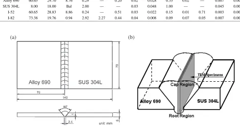
70706mm were machined from the two base metals, and welded by means of the GTAW. Inconel 52 and 82 filler wires were 2.4 mm in diameter. The chemical compositions of the base metals and filler wires are provided in Table 1.
Figure 1(a) presents an illustration of the weldment design. The bevelled-edge plates were welded to form an 80single V-groove with a 2.4 mm root gap and a 1 mm root face. An argon gas of 99.9% purity was used as the shielding gas. Prior to welding, the surfaces of the filler metals, base metals, and clamps were thoroughly cleaned with acetone to remove any residual grease and ink. This is an important step since sulfur and phosphorous in grease and ink can lower the surface free energy of a liquid-solid interface and hence increase the hot cracking susceptibility of the weldment. A four-layered weld of either I-52 or I-82 was deposited in six welding passes. Following each welding pass, the welding process was halted until the inter-pass temperature fell below 150C. During the inter-pass interval, the slag on the
weldment was removed. Appropriate parameters were adopted to ensure the proper fluidity of the molten pool during the welding process. Table 2 is a summary of the welding parameters and the corresponding heat inputs.
SEM specimens were sampled from the middle of a fusion zone. The electrolytic etching was performed using a reagent
of 70 mL H3PO4+30 mL H2O under a potential of 6 V DC for
about 25 seconds. The dilution of base metal was calculated by measuring the change of area in base metals. The dilution in the cap and root was about 25% and 60–65%, respectively. Thin foils and carbon extraction replicas for TEM investigation were prepared from specimens taken from the central fusion zone of a weldment, as shown in Fig. 1(b). The thin foils were prepared by electropolishing at 10C in a
solution of 10 pct perchloric acid and 90 pct ethanol. The carbon extraction replicas were made through a process of double-sided extraction replication. Microstructural analyses were conducted by means of TEM, EDXS, and EFTEM using
a JEOL 2000FX and an FEI Tecnai 20F microscope operating at 200 kV.
3. Results
3.1 Base metal
An optical micrograph of Alloy 690 is shown in Fig. 2(a). Precipitates were dispersed in the matrix and along the grain boundary. The rectangular precipitates in the matrix were TiNs, which were larger than those along the grain boundary and showed a golden color under the optical microscope. The precipitates along the grain boundary were thought to be
[image:2.595.47.552.85.148.2]Cr-Fig. 1 Sketch diagrams (a) of weldment design and (b) of TEM specimen position in the fusion zone.
Table 2 Procedures and parameters for gas tungsten arc welding.
Welding parameters Specimen Pass
sequence Pass
number Current, A
Voltage, V
Speed, mm s-1
Heat input, kJ mm-1
Total heat input, kJ mm-1
[image:2.595.47.538.105.366.2] [image:2.595.85.508.420.619.2]carbides. Figure 2(b) is an optical micrograph of SUS 304L base metal. Twins and -ferrite were observed in the austenitic matrix.
3.2 Analyses of interdendritc phases
The compositional variations between the base metal and fusion zone were analyzed with an SEM/EDS. Figure 3 shows the line scan results of the root region. As shown in Figs. 3(c) and 3(d), wide variations in Ni and Fe contents
were observed between the fusion zone and the SUS 304L base metal. On the side of Alloy 690, only little composi-tional variations were observed. In the I-82 fusion zone, the Nb content showed periodical change, as shown in Fig. 3(b) and Fig. 3(d), which could be accounted for by the formation of Nb-rich interdendritic phases. I-52 had a higher Cr contents (30mass%) in the fusion zone than I-82 (20
mass%). A rise in Cr contents by about 10 mass% in I-52 should have beneficial effect on corrosion resistance
com-Fig. 2 Optical micrographs of (a) Alloy 690 and (b) SUS 304L.
[image:3.595.99.497.72.196.2] [image:3.595.99.499.234.626.2]pared with I-82. Based on the change in the fusion zone area, the dilution was calculated to be about 60–65% in the root region for both I-52 and I-82.
The width of the transition zone, in which the composition varied remarkably, was estimated to be about 50–100mm, as shown in Fig. 3. By contrast, the chemical compositions of the central fusion zone remained relatively constant. Thus, the specimens for TEM examination were taken from the central fusion zone, as shown in Fig. 1(b).
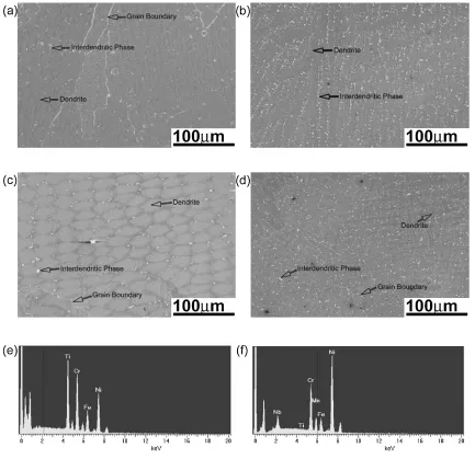
Figure 4 shows the precipitates in the central region of the two fusion zones. The white points and white lines were the interdendritic phases and grain boundaries, respectively. Results of EDS analysis showed that the interdendritic phases in the I-52 fusion zone were Ti-rich phase, but that the interdendritic phases in I-82 were rich in Nb, as shown in Fig. 4(e) and Fig. 4(f).
Besides, in the I-52 fusion zone, as shown in Fig. 4(a) and Fig. 4(c), there were more and larger interdendritic phases in the root region than in the cap region. In comparison, I-82 showed a reverse result that the root region had less and
smaller interdendritic phases than the cap region, as shown in Fig. 4(b) and Fig. 4(d). It could be attributed to significant dilution of the root region with base metals. On the whole, more interdendritic phases were present in the I-82 fusion zone than in the I-52 fusion zone because of its higher Nb content.
3.3 Characterization of precipitates
3.3.1 Fusion zone of weld with alloy I-52 filler
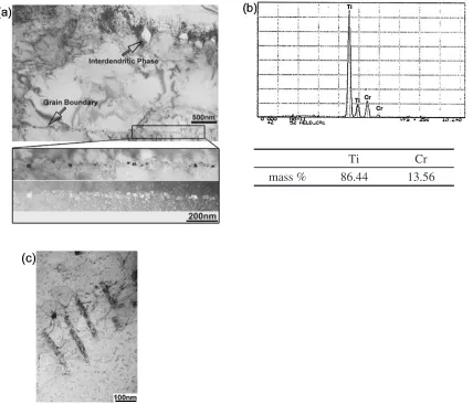
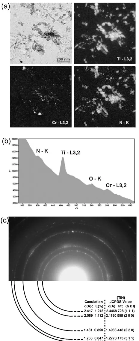
The matrix of the I-52 fusion zone was of an austenitic structure. In the cap region, Ti-rich precipitates in the interdendritic region were about 200 nm across the diagonal, as shown in Figs. 5(a) and 5(b). Furthermore, some small precipitates were also observed in the matrix and along the grain boundary, as shown in the inset of Fig. 5(a) and Fig. 5(c). On the TEM micrographs, they were rectangular in shape and measured to be about 40 nm in size. These precipitates were rich in Ti and N, and of fcc structure with a lattice parameter 0.420 nm, as shown in Fig. 6. According to the ring pattern, they were identified as Ti-nitrides. Figure 6
[image:4.595.82.515.71.490.2]also shows some TiNs without Cr were smaller in size and had a shape of rounded-rectangular or oval form. They were assumed to be unmelted residue due to their high melting point and short welding time. No Cr carbides were found in the cap region.
In the root region, small Cr-rich phases were found near the large Ti-nitrides that were larger than those in the cap region and base metals, as shown in Fig. 7(a). Figure 7(b) shows the ring patterns of the Ti-nitrides and Cr-rich phases. Some ring patterns with high intensity were similar to those Ti-nitrides in the cap regions, while the Cr-rich phases could be a mixture of various types of Cr-carbides.
The root region was made by the first pass of the welding process. Cr-carbides were observed to precipitate along the grain boundary or interdendritic regions, which could be induced by the thermal cycling due to the subsequent welding passes. Figure 8 shows that the average contents of Cr in the cap and root regions were at the same level of 29 mass%. However, unlike the uniform distribution of Cr in the cap region, there was a sharp drop in the Cr content near the grain boundary of the root region. Cr depletion in the vicinity of grain boundary provided indirect evidence for the formation of Cr-rich precipitates on the grain boundary.
3.3.2 Fusion zone of weld with alloy I-82 filler
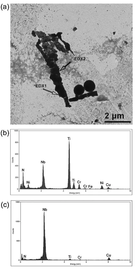
Figure 9(a) shows the interdendritic phases formed in the
I-82 fusion zone. They were identified as Ti-Nb phases with small amounts of Cr and Ni, as shown in Figs. 9(b) and 9(c). A remarkable nitrogen peak in the spectrum of Ti-Nb phases was also noted when titanium was the dominant constituent. Comparing Fig. 9 with Fig. 4(f) showed that the results of TEM-EDX analyses of the interdendritic phases seemed in contradiction to those from SEM-EDX analyses. Theoret-ically, the spatial resolution and excited volume of SEM-EDX are about 0.1mm and 1mm3, respectively, whereas those of TEM-EDX are about 10 nm and 105mm3.13) In addition, the specimens of TEM-EDX were extraction replicas that only consisted of interdendritic phases/precip-itates. Thus, the compositions of interdendritic phases obtained by TEM-EDX analyses would be more accurate than those by SEM-EDX.
The addition of Nb would promote the precipitation of interdendritic phases when its concentration is greater than the maximum solubility of Nb in the austenitic matrix. Nb could compound with Ti, from both of I-82 and Alloy 690, to form Ti-Nb nitrides in the fusion zone. Figures 9(b) and 9(c) show that the compositions varied with the location analyzed. Thus, we assumed this interdendritic phase was a mixture of Ti-N-rich phase and Nb rich phase. Referred to the observation in Fig. 6, some of the Ti-N-rich phases in Fig. 9 might be the un-melted TiNs from Alloy 690.
Ti
Cr
mass %
86.44
13.56
[image:5.595.88.516.73.439.2] [image:5.595.311.512.73.241.2]In the cap region, tiny precipitates in irregular shape were observed in the matrix and along the grain boundary, as shown in Fig. 10(a). Typical Ashby-Brown contrast observed in Fig. 10(b) suggested that there were small misfitted precipitates with an approximately spherical strain field in the matrix. Most of the precipitates, as revealed in Fig. 11, were about 100 nm in size, which could be observed along the grain boundaries in the cap region, as shown in Fig. 10.
were about 20 mass% and 25 mass%, respectively, as shown in Fig. 13. It was noted that the root region had a higher Cr content than the cap region. The dilution of base metals could account for this.
4. Discussion
Alloy 52 and Alloy 82 were composed of different contents of Cr, Ti and Nb, which led to marked differences in the microstructural characteristics and mechanical proper-ties. In the I-52 fusion zone, the dominant precipitates were Ti-nitrides. But in the I-82 fusion zone, they were Ti-Nb-rich phase that had a higher nitrogen level when titanium was the dominant constituent.
Although all of the base metals and filler metals had low carbon contents, Cr-carbides were found to precipitate along the grain boundary and near the interdendritic regions of the I-52 root region. On the contrary, no obvious precipitation of Cr-carbides was observed in the I-82 root region. The Nb addition could reduce the precipitation of Cr-carbides in the root region of I-82.
The grain boundary and interdendritic region are the preferable sites for precipitation of Cr-carbides. In this study, the welding heat is periodically generated due to the multi-pass welding. With the welding heat, the precipitation of Cr-carbides is often induced. The quantity of carbon atoms available would affect the amount of Cr-carbide to precip-itate.
Ti and Nb are often used to stabilize carbon atoms. In nickel-based alloys, the nitrogen content increases with increasing chromium content. Ti is also employed to stabilize N atoms to avoid porosity formed in nickel alloys when it solidifies.14)In this study, the Ti content in the I-52 was too low to reduce the precipitation of Cr-carbides in the root region. To the contrary, I-82 had an Nb content about 2 mass%, which was sufficient to decrease the Cr-carbides to precipitate in the root region.
The Cr content near the grain boundary decreases as a result of Cr-carbide precipitates. It has been proposed that the Cr depletion caused by the Cr-carbide precipitation along the grain boundary results in a reduction in the corrosion resistance to intergranular attack (IGA).15) However, many
studies have shown that Alloy 600 would be susceptible to IGA only when the Cr content near the grain boundaries is lower than 9 mass%. Thus, these two weldments could not be susceptible to IGA.
In addition, a rich coverage of carbides along the grain-boundary in Alloy 600 would enhance the resistance of SCC in the low dissolved-oxygen water of PWR environment.15,16) The favorable SCC corrosion resistance properties of Alloy
[image:6.595.54.286.69.637.2]690 and Alloy 52 in an oxygenated water environment are considered to be the result of the higher chromium content.17,18)Similarly, the heat treatment of Alloy 690 could further enhance its corrosion resistance.19) The latest study has demonstrated that Cr-carbides along the grain boundary
could prevent diffusion of Cr from the matrix to form Cr-oxide, which is also thought to be the most effective against SCC in the PWR water environment.20)The precipitation of Cr-carbides in the root region of the I-52 fusion zone could be a reason to account for its good SCC resistance.
5. Conclusions
This study has investigated the dissimilar weldments of Alloy 690 and SUS 304L, which have been butt welded using GTAW with Inconel 52 and 82 filler metals. Close micro-structural analyses have been performed on specimens sampled from various locations within the corresponding fusion zones. The results of this microstructural analysis are summarized as follows:
(1) The fusion zones of both the I-52 and the I-82 had a lot of precipitates of various sizes in the interdendritic region and along the grain boundary. More interden-dritic phases were observed in I-82 than in I-52. (2) The tiny TiN with fcc lattice structure (a¼0:420nm)
No.d(A) Intensity Calculation/ JCPDS ValueTiN Cr23C6
JCPDS Value Cr7C3
JCPDS Value Cr3C2
JCPDS Value
1 3.728/ very low 3.7653 7 (2,2,0) 3.9822 24 (1,0,2) 2 3.174/ very low 3.1457 17 (1,3,0) 3 2.607/ low 2.6625 49 (4,0,0) 2.5462 245 (0,1,4) 4 2.413/ low 2.4468 728 (1,1,1) 2.4432 10 (3,3,1) 2.4602 91 (1,1,1) 5 2.336/ medium 2.3814 228 (4,2,0) 2.2969 33 (1,5,0) 2.3062 999 (1,1,2) 6 2.132/ medium 2.1190 999 (2,0,0) 2.1739 284 (4,2,2) 2.1231 46 (1,1,2) 2.2414 590(2,0,3) 7 2.071/ high 2.0495 999 (5,1,1) 2.0489 100 (1,5,1)
8 2.014/ medium 1.8826 217 (4,4,0) 1.8161 24 (2,2,2) 1.8698 418 (2,1,2) 9 1.848/ medium 1.7750 123 (4,4,2) 1.7546 16 (2,6,0) 1.7819 230 (0,1,5) 10 1.770/ low 1.6839 19 (6,2,0) 1.6122 2 (3,1,2) 1.6961 208 (1,1,5) 11 1.659/ low 1.5195 2 (0,8,0) 1.5713 33 (2,0,6) 12 1.578/ low 1.4403 1 (0,3,3) 1.4980 45 (2,1,5) 13 1.482/ medium 1.4983 448 (2,2,0) 1.3312 30 (8,0,0) 1.3526 7 (2,2,3) 1.3274 22 (3,0,6) 14 1.315/ very low 1.2551 134 (6,6,0) 1.2621 3 (1,5,3) 1.2461 83 (1,1,8) 15 1.259/ medium 1.2778 173 (3,1,1) 1.2297 79 (7,5,1) 1.2151 3 (5,5,0) 1.2354 40 (4,1,1) 16 1.237/ very low 1.2216 4 (6,6,1) 1.2106 12 (3,3,3) 1.1962 91 (2,2,3) 17 1.212/ low 1.2234 114 (2,2,2) 1.1907 34 (8,4,0) 1.187413 (2.8,2) 1.1818 79 (4, 1 ,3) 18 1.177/ very low 1.1689 41 (9,1,1) 1.1706 12 (5,2,2) 1.1531 45 (2,2,4) 19 1.150/ very low
20 1.074/ very low 21 1.054/ very low 22 1.000/ very low
Fig. 7 Analysis of TiN and Cr-carbides in the I-52 root region: (a) bright field image and EFTEM images, and (b) diffraction pattern.
0 5 10 15 20 25 30 35
0 0.05 0.1 0.15 0.2 0.25
Distance from Grain boundary (µm)
Cr Concentration (mass %)
cap region root region
[image:7.595.83.517.68.504.2] [image:7.595.57.284.549.686.2]Fig. 9 Analysis of Ti-Nb phases in the I-82 cap region: (a) bright field image, (b) EDX1, and (c) EDX2.
[image:8.595.312.540.73.488.2]Fig. 10 Bright field image (a) of tiny precipitates along the I-82 grain boundary and (b) Ashby-Brown contrast in the matrix.
[image:8.595.129.466.612.769.2]had been observed in the I-52 fusion zone. Owing to the thermal cycles of subsequent welding passes, Cr-carbides precipitated in the root region.
(3) In the I-82 fusion zone, precipitates in the cap and root regions were identified as a mixture of tiny Ti-rich and Ti-Nb-rich phases having fcc structures with lattice parameters of 0.424 nm and 0.438 nm, respectively.
Acknowledgement
The authors would like to acknowledge the finical support from National Science Council (NSC), Republic of China
(Taiwan), under Grant No. NSC-TPC-E-006-013 and the Sandwich Program between Taiwan NSC and Germany Academic Exchange Service (DAAD).
REFERENCES
1) W. Bamford and J. Hall:11th Int. Conf. Environmental Degradation of Materials in Nuclear Systems-Water Reactors, ed. by G. S. Waset al., (Stevenson, Washington, August 10–14, 2003), pp. 1071–1081. 2) W. Bamford and J. Hall:12th Int. Conf. Environmental Degradation of
Materials in Nuclear Systems-Water Reactors, ed. by L. Nelsonet al., (Salt Lake City, Utah, August 14–18, 2005), pp. 959–966.
3) B. Grimmel:U.S. Plant Experience with Alloy 600 Cracking and Boric Acid Corrosion of Light-Water Reactor Pressure Vessel Materials, (NUREG-1823, 2005) pp. A9–A25.
4) J. C. Thornley: Weld. J.8(1973) 355s–358s.
5) R. A. Page and A. McMinn:Stress Corrosion Cracking Resistance of Alloys 600 and 690 and Compatible Weld Metals in BWRs, EPRI NP-5882M, July 1988.
6) H. T. Lee and T. Y. Kuo: Sci. Tech. Weld. Join.4(1999) 94–103. 7) W. T. Wu and C. H. Tsai: Metall. Trans. A30(1999) 416–426. 8) H. T. Lee and S. L. Jeng: Sci. Tech. Weld. Join.6(2001) 225–234. 9) C. M. Brown and W. J. Mills: Corrosion55(l999) 173–186. 10) R. A. Page: Corrosion39(1983) 409–421.
11) A. McMinn and R. A. Page: Corrosion44(1988) 239–249. 12) T. Y. Kuo and H. T. Lee: Mater. Sci. Eng. A338(2002) 202–212. 13) D. B. Williams and C. B. Carter:Transmission Electron Microscopy,
(Plenum Press, New York, 1996) pp. 631–633.
14) R. T. Holt and W. Wallace: Inter. Metals Rev.3(1976) 1–24. 15) G. S. Was: Corrosion46(1990) 319–330.
16) O. K. Chopra, W. K. Soppet and W. J. Shack: Effects of Alloy Chemistry, Cold Work, and Water Chemistry on Corrosion Fatigue and Stress Corrosion Cracking of Nickel Alloys and Welds, (NUREG/CR-6721, ANL-01/07, 2001), pp. 14–15.
17) J. R. Crum and R. C. Scarberry: J. Mater. Energy Systems4(1982) 327–341.
18) H. Nagano, K. Yamanaka, K. Kobayashi and M. Inoue: The Sumitomo Search40(1989) 57–70.
19) J. R. Crum: Corrosion42(1986) 368–372.
[image:9.595.54.283.66.503.2]20) M. Scott, P. Combrade:11th Int. Conf. Environmental Degradation of Materials in Nuclear Systems-Water Reactors, ed. by G. S. Waset al., (Stevenson, Washington, August 10–14, 2003), pp. 29–38.
Fig. 12 Analyses of tiny Ti-Nb-N particles in the I-82 root region: (a) EFTEM images and (b) diffraction ring pattern.
0 5 10 15 20 25 30 35
0 0.05 0.1 0.15 0.2 0.25
Distance from Grain boundary (µm)
Cr Concentration (mass %)
cap region root region
[image:9.595.311.540.75.207.2]