Mechanism of the Improvement of Shape Memory Effects
in NbC Containing Fe-Mn-Si-Based Shape Memory Alloys
*K. Ogawa, T. Sawaguchi, T. Kikuchi and S. Kajiwara
National Institute for Materials Science, Tsukuba 305-0047, Japan
High-resolution transmission electron microscopy revealed that the NbC carbides precipitating in Fe-Mn-Si-based shape memory alloys in the orientational relationship of½100f==½100NbC,ð001Þf==ð001ÞNbCare partially coherent with the matrix showing the misfit dislocations on
every fiveð002Þflayers. It was also found that the pre-warm rolling prior to the aging refines the NbC carbides into sizes as small as about 5 nm and produces a homogeneous distribution. It was statistically clarified that the deformation microstructures of the Fe-Mn-Si-based alloys containing finely dispersed NbC carbides exhibit nano-sized monopartial stacking martensite plates, similar to those of the conventional Fe-Mn-Si-based alloys subjected to the training treatment. These microstructural features are considered to improve the shape memory properties of the alloys. [doi:10.2320/matertrans.48.869]
(Received December 18, 2006; Accepted February 19, 2007; Published March 25, 2007)
Keywords: iron-based shape memory alloy, NbC carbide, high-resolution electron microscopy, monopartial stacking, stress-induced martensitic transformation, Shockley partial dislocations
1. Introduction
Fe-Mn-Si-(Cr)-(Ni) alloys are known to be a low-cost shape memory alloy (SMA) with good mechanical proper-ties, good machinability and good weldability.1,2)In compar-ison to Ni-Ti-based SMAs, the two-way shape memory effect (SME) and transformation pseudoelasticity of the SMAs are very low because of their nonthermoelastic nature. On the other hand, the one-way SME with a wide transformation hysteresis in the SMAs is advantageous for some applica-tions, such as coupling pipes, and there have been some examples used in practical applications.3) The use of the
SMAs as a reinforcement in plaster or concreting materials is also proposed.4,5)
It is known that the SME of the Fe-Mn-Si-based SMAs is improved by a special thermomechanical treatment called ‘training’, which consists of several cycles of slight defor-mation and subsequent shape recovery heating.6) The
improvement of the SME by training is ascribed to the yield stress of the austenite increasing as a result of work hardening; the stress for inducing martensitic transformation is decreased because of the formation of stacking faults, which act as nucleation sites for the martensite. The evolution of the internal microstructure and deformation structure through training has been clarified by degrees. Ogawa and Kajiwara revealed by high-resolution transmission electron microscopy (HREM) that the width of the martensite plates is refined into several nanometers by training.7,8) Liu et al.
observed the deformation microstructures of the SMAs by atomic force microscopy (AFM) and reported that the stress-induced martensite formed in the trained specimens has a single shear component on a particular habit plane,i.e., in the monopartial stacking state.9)
Based on these observations, NbC-containing Fe-Mn-Si-based SMAs were developed, which were aimed to show good SMEs comparable to the trained specimens by imitating
their above-mentioned microstructures. Kajiwara et al. attempted to obtain a microstructure consisting of very thin martensite plates of a single variant by adding a small amount of Nb and C to the conventional Fe-Mn-Si-based SMAs and subsequent aging treatment to precipitate coherent NbC carbides with a nanometer size. As a consequence, they succeeded in improving the SME to a large extent without performing the training treatment.7,8)
It was also found that various pre-deformations, such as warm rolling, cold rolling, or tensile deformation at room temperature, prior to the aging treatment further improve the SME of the NbC-containing SMAs, which results in improving the SME to the level of the trained speci-mens.10–16) These processes are simpler than that of the
training treatment and thus will lower the processing cost. Among these thermomechanical treatments, the pre-warm rolling and subsequent aging appeared to bring about a good SME independent of the rolling direction, which allows various shapes of the final products. Another advantage of the NbC-containing specimens subjected to the thermomechan-ical treatments is the shape recovery stresses higher than those of conventional SMAs without precipitates. All of these advantages of the newly developed SMAs are beneficial for practical use.
In the NbC-containing Fe-Mn-Si-based alloys, fine NbC carbides coherently precipitate in the parent phase and are thought to contribute to the improvement of the SME. In the present study, we observed the deformation microstructure on an atomic scale by HREM and discuss the reason why the SME is improved without training.
2. Method of Sample Preparation
Two alloys with the chemical compositions of Fe-28Mn-6Si-5Cr-0.53Nb-0.06C (mass%) and Fe-14Mn-6Si-9Cr-5Ni-0.53Nb-0.06C produced by vacuum induction melting were used. Hereinafter, we call these alloys ‘Fe28Mn’ and ‘Fe14Mn’, respectively. The former alloy shows the best SME among the developed alloys. The latter alloy has good
*This Paper was Originally Published in Japanese in J. Japan Inst. Metals
70(2006) 25–33.
corrosion resistance comparable to stainless steels, though its SME is slightly less than the former. After hot-forging and rolling at 1270 K in an argon atmosphere, the specimens underwent a homogenization/solution treatment at 1470 K for 10 h. To produce the NbC carbides, we further subjected them to a thermomechanical treatment, which consisted of warm rolling at 870 K with various amounts of rolling and subsequent heat treatment at 1070 K for 10 min. After examining a number of specimens by HREM, we succeeded in observing the lattice images of the NbC carbides coherently precipitating in the austenite matrix for the Fe28Mn alloy subjected to warm rolling by 6% and 14% and for the Fe14Mn alloy subjected to warm rolling by 20%. Hereinafter, the specimens will be referred to by the amount of rolling as ‘6%-rolled’, ‘14%-rolled’, and ‘20%-rolled’ specimens. It has been found that the combinations of the above-mentioned alloy compositions and the thermomechan-ical treatments lead to good SMEs that are comparable to the trained specimens without NbC.13,15) As a reference, an
Fe28Mn specimen, which was subjected only to aging at 1070 K for 10 min without pre-deformation, was also prepared (0%-rolled specimen).
The specimens for the HREM observations were prepared by chemical and electrolytic polishing. They were first thinned to 0.2 mm thick by chemical polishing, using a solution consisting of hydrofluoric acid, hydrogen peroxide and water (1:10:2 in volume). The plate specimens were masked and dissolved in the same solution to obtain discs of 3 mm diameter. The discs were further subjected to electrolytic polishing at room temperature, using an electro-lyte consisting of acetic acid and perchloric acid (4:1 in volume).
3. Results
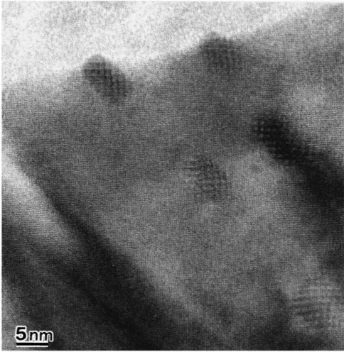
A transmission electron microscopic (TEM) image of the Fe28Mn alloy rolled by 6% is shown in Fig. 1. The orientational relationship between the NbC precipitate and the parent phase (fcc) is ½100f==½100NbC, ð001Þf== ð001ÞNbC, which is called the cube-cube orientational
relationship. Figure 1 was taken in the ½100f==½100NbC
direction. The NbC carbide particles with a grain size of several nanometers are homogeneously dispersed in the austenite matrix and accompanied by Moire interference fringes. For the 0%-rolled specimen, the size of the NbC precipitates is larger than that of the pre-deformed specimen, as shown in Fig. 2. The clustering of several NbC particles is also observed at the places indicated by arrows. Accordingly, the warm rolling prior to the aging refines and homogenizes the dispersion of the NbC precipitates. The improvement of the SME by pre-warm rolling may be attributed to such a change in the NbC distribution.
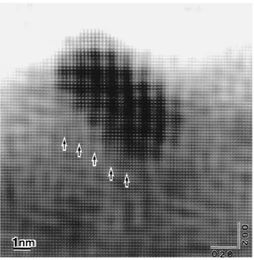
Figure 3 shows the details of an NbC carbide in Fig. 1, which was enlarged and then subjected to a Fast Fourier Transformation (FFT) treatment. The area with a dark contrast at the center of the image is of the NbC precipitate. This figure shows that five {002} layers of the austenite correspond to four {002} layers of NbC at the interface. In other words, there are extra half-planes in the austenite on every five atomic layers. This can be reasonably explained by the difference of d spacings for thef002gfbetween the matrix
and NbC, which are df(002)¼0:1802nm for the austenite and
Fig. 1 The transmission electron micrograph of an Fe-28Mn-6Si-5Cr-0.53Nb-0.06C alloy subjected to 6% rolling at 870 K and subsequent aging. The homogeneously dispersed NbC carbides with several nano-meter dianano-meters are observed while showing Moire patterns.
Fig. 2 The transmission electron micrograph of the Fe-28Mn-6Si-5Cr-0.53Nb-0.06C alloy subjected to aging without pre-rolling. The size of the NbC carbides is as large as several tens of nanometers, and they form a cluster.
[image:2.595.47.289.73.321.2] [image:2.595.303.549.73.363.2]dNbC(002)¼0:2235nm for the NbC precipitate. These extra
half-planes are thought to be misfit dislocations.
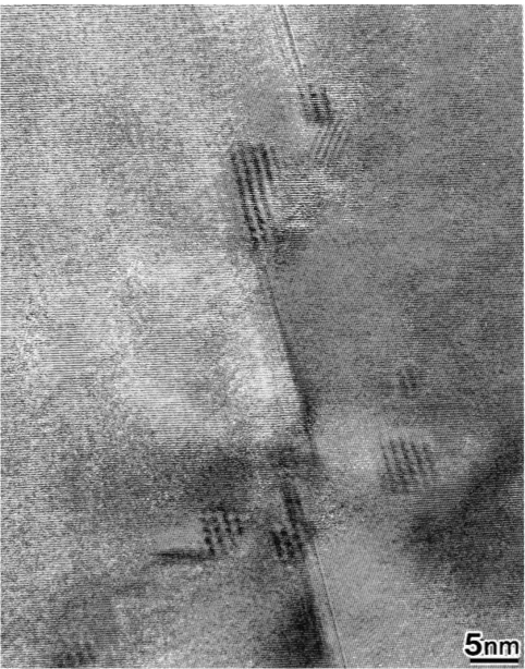
Figure 4 is the TEM image concurrently showing the NbC precipitates and stacking faults observed in the 20%-rolled specimen of the Fe14Mn alloy. The stacking faults are thought to be induced during pre-warm rolling. The image is taken in the incident beam direction of½110f, which has a
relation of an edge-on for the stacking faults. The NbC precipitates are homogeneously dispersed, and the stacking faults are connected to them. It is inferred from this image that the NbC preferentially precipitate on the stacking faults induced during warm rolling prior to the aging. Figure 5 is an enlarged FFT image of an NbC precipitate that shows the lattice image. At the lower interface between the NbC precipitate and the austenite, the atom rows of both phases are continuously connected except for the arrowed places where the strain of the lattices are cleanly seen. This is due to the existence of the misfit dislocations at the austenite (fcc)/ NbC interface observed in Fig. 3.
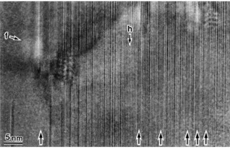
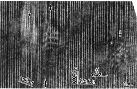
Figure 6 shows a low magnification lattice image of the 14%-rolled specimen of the Fe28Mn alloy, which was further subjected to deformation by tension to 4.4%. The image was taken in the ½110f incident direction. An arrow with h
indicates the martensite phase (hcp), which can be
deter-mined by the stacking order of atom rows along the h direction. The direction along the arrow of h corresponds to the ð00:1Þh plane. An arrow with f indicates the austenite
phase (fcc), which can also be determined by the stacking order of atom rows along the f direction. The direction along the arrows of f corresponds to the ð11111Þf plane. Figure 7
shows an enlarged image of the lower right of Fig. 6, in which the lattice image consisting of the atom rows on the
ð00:1Þhplanes and on theð10:0Þhplanes are seen. There are
very thin austenite plates at the places indicated by the upward-pointing arrows, in which atom arrays corresponding toð11111Þf can be seen. The lattice planes observed in Fig. 7
well satisfy the interplanar spacing of both the austenite and martensite crystals: 0.42 nm forð00:1Þh, 0.242 nm forð10:0Þh,
and 0.21 nm forð11111Þf. Figure 8 shows an enlarged image of
an NbC carbide, which was taken using the same specimen as that of Fig. 6. Extremely thin austenite plates are observed as indicated by upward-pointing arrows in the martensite. Downward-pointing arrows indicate the NbC carbides. In the vicinity of the NbC/austenite or NbC/martensite inter-faces, the atomic arrangement is irregular because of the coherent strain.
A number of HREM images similar to that shown in Fig. 6 were taken from various areas in the same specimen to Fig. 3 An enlarged FFT image of an NbC carbide obtained from a part of Fig. 1. The dark contrast shown in the center is the NbC
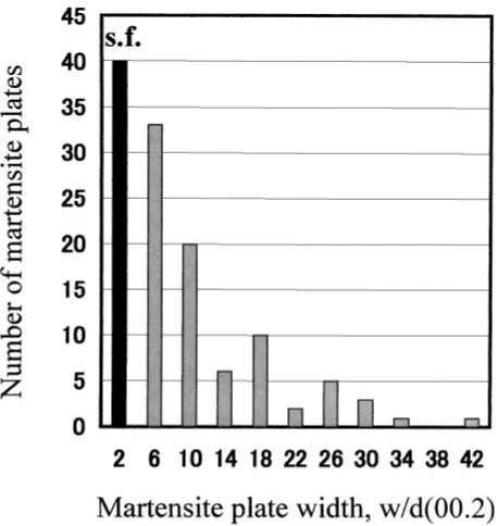
[image:3.595.113.484.69.448.2]investigate the existing probabilities of martensite plates having various widths. Figure 9 exhibits a histogram show-ing the distribution of the martensite plate width, where interplanar spacing of theð0002Þhplane (¼0:21nm) is used
as a unit of width. Most of the martensite plates have widths of less than 20 layers. Figure 10 shows more detailed histograms for the plate widths of less than 50 layers. It is obvious that the martensite plates with extremely small widths are induced with a very high probability. A martensite plate consisting of twoð00:2Þhlayers in width corresponds to
a stacking fault in the austenite. The present authors7)also performed a similar investigation on a training-treated Fe-14Mn-6Si-9Cr-5Ni alloy without NbC and reported the distribution of the martensite plate width similar to that obtained in the present NbC-containing alloy.
4. Discussion
The HREM observations revealed that the Fe-Mn-Si-based SMAs containing finely dispersed NbC carbides show a deformation microstructure containing ultrafine martensite plates with widths on the nanometer order, similar to that of the training-treated non-NbC Fe-Mn-Si-based alloys. Re-cently, Liuet al.9)and Barujet al.13)reported on the basis of the AFM analyses that the stress-induced martensite formed in the NbC-containing Fe-Mn-Si-based alloys is of ‘‘monop-artial stacking’’, similar to that formed in the training-treated non-NbC Fe-Mn-Si-based alloys. Accordingly, we can
conclude that the NbC-containing alloys show the above-mentioned two microstructural features similar to the train-ing-treated non-NbC alloys without being subjected to the training treatment. In this section, we discuss the reason why the shape memory characteristics are improved by this deformation microstructure characterized by the extremely thin monopartial stacking martensite.
The formation of the hcp martensite is accomplished by the shear ofa=6h112i on every two {111} layers in the fcc austenite. For the stress-induced transformation, the monop-artial stacking martensite constructed of the shear in a particularh112if direction on a particularf111gf habit plane
among twelve f111gh112i shear systems is quite likely to form as a result of the external stress. On the other hand, when the reverse transformation is induced by heating, three kinds of h112i shears can occur with an equal probability because there is no driving force to specify the shear direction. As a result, although the crystalline structure after the reverse transformation is the same as that before the deformation, the external shape is different from the initial one, resulting in an incomplete shape memory effect. On the contrary, if the shear on the path just opposite to the former transformation can be intentionally selected as the path for the reverse transformation, a larger shape recovery fraction is expected.
It was found by HREM observations of the deformation microstructure of the training-treated specimens that ex-tremely thin martensite plates with thicknesses of less than 1 nm are formed in an overwhelming majority. It was also directly observed that a large elastic strain field is formed at the tip of the martensite plates.8)The fcc!hcp martensitic
transformation caused by the a=6h112i shear on every two
f111gf layers brings about the stacking fault on every two f111gf layers, on the growing top of which the leading
Shockley partial dislocation exists. The elastic strain field around the tip of the martensite plates may be caused by these dislocations. During the reverse transformation upon heating, the tip of the martensite plates moves backward, being assisted by this large elastic strain. Thus the reverse trans-formation takes the crystallographic path the same as that in the forward transformation as a result of the back stress on the growing tip of the martensite, which leads to the nearly perfect SME. This is possibly why the shape memory effect is improved by training. The elastic strain field around the tips or the ledges of the martensite is also observed in the NbC-containing alloys. Figure 11 shows an example of the elastic strain field in the austenite around a ledge of an extremely thin martensite plate, which was observed in the 14%-rolled specimen of the Fe28Mn alloy. The lattice image around the ledges of a martensite plate with a width of 1.5 nm, which are indicated by arrows, is indistinct over about 2 nm probably because of the large internal strain caused by the Shockley partial dislocations.
The reason why the thin martensite is preferable for producing the back stress from Shockley partial dislocations is considered to be as follows. A thickening of the monopartial stacking martensite leads to increases in the number of Shockley partial dislocations with the same Burgers vector. The dislocations with the same sign repel one another and are very likely to induce a shear system that Fig. 4 The transmission electron micrograph of an
Fe-14Mn-6Si-9Cr-5Ni-0.5NbC alloy subjected to 20% rolling at 870 K and subsequent aging. The NbC precipitates are connected by stacking faults, which are considered to be introduced during pre-rolling.
[image:4.595.48.289.71.378.2]Fig. 5 Enlarged FFT image of an NbC carbide and stacking faults obtained from a part of Fig. 4.
[image:5.595.116.484.68.397.2] [image:5.595.71.524.466.758.2]Fig. 8 NbC precipitates in a deformed microstructure. The downward arrows indicate NbC precipitates; the upward arrow indicates the very thin austenite plate.
Fig. 7 The enlarged lattice image from Fig. 6. The atom arrays corresponding toð00:1Þhandð10:0Þhcan be seen. The arrows indicate the
very thin austenite plates.
[image:6.595.71.527.71.365.2] [image:6.595.73.525.464.757.2]relieves the repulsion force. Consequently, the martensite variants in the direction different from the predominant one are formed, which constitute the ‘multipartial stacking’ martensite. It was experimentally observed in a non-NbC SMA without being subjected to the training that the degradation of the SME is associated with the occurrence of the multiple variants with different shear components, which are formed when the specimen is severely deformed.9)
On the other hand, it is easy for thin martensite plates to maintain the state of monopartial stacking. To understand this, for example, we must compare cases. In one, the tip of one monopartial stacking martensite plate consisting of one hundred f00:2gh layers is involved in a certain area. In the
other, the tips of ten monopartial stacking martensite plates consisting of tenf00:2ghlayers are involved in the same area.
The total shear resulting from the martensitic transformation and the density of the Shockley partial dislocations in the certain area are the same for both cases. In the former, the partial dislocations and the corresponding elastic strain field are located around the tip of the large martensite, but in the latter, the very thin martensite plates and the remaining austenite plates are alternatively stacked to form a lamellar structure; thus partial dislocations and the corresponding elastic strain field are widely distributed. It is inferred from this comparison that thinning the martensite plates prevents a concentration of the local stress, maintaining a monopartial stacking state. In particular, it is self-evident that the martensite consisting of two f00:2gh layers is in the
monopartial stacking state corresponding to a stacking fault in the austenite.
It is also plausible that when the tips of fully grown martensites reach a grain boundary, the partial dislocations residing on the tips with the associated back stresses are absorbed into the boundary. In contrast to this, the thin martensite with its tip inside the grain preserves the back stress onto the tip, which originates from the partial dislocations residing on the tip. In the AFM images taken by the present research group,17)it was often observed that
martensites having tips inside grains can perfectly transform to the austenite by heating. Therefore the favorable defor-mation microstructure for obtaining a good SME is consid-ered to have the following features: (1) Thin martensite plates with monopartial stacking are formed in the same direction on the identical habit plane, resulting in the austenite/ martensite lamellar structure; (2) The tips of the martensite plates do not reach the grain boundaries.
[image:7.595.53.284.68.327.2]The refinement of the martensite during the training treatment may be explained by the fact that the density of the stacking faults produced in the austenite, which may act as a Fig. 10 A detailed histogram showing a distribution of the martensite plate
width below 40 ð00:2Þh layers. The martensite plates with twoð00:2Þh
[image:7.595.307.546.72.245.2]layers in width are stacking faults in the austenite.
Fig. 11 An FFT image of the ledge structure in an hcp martensite plate with an extremely thin width of about 1.5 nm.
[image:7.595.55.284.390.632.2]nucleation site for the martensite, increases with the increasing number of training cycles. The refinement of the martensite in the NbC-containing alloys is ascribed to the extremely fine NbC carbides (about 5 nm in diameter) produced by the aging treatment, which can also act as the nucleation sites for the martensite. It has been widely accepted that the improvement of the SME obtained by the training treatment is caused by the increase in the yield stress of the austenite because of the work hardening and by the decrease in the stress for inducing the martensitic trans-formation through the repetition of straining and heating.6)
Intensive attempts to improve the SME using the precip-itation hardening have been made based on this idea.18–20)
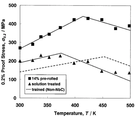
However, the SME in the alloys obtained in these kinds of attempts is not much better than that in the conventional alloys. Figure 12 shows the relationship between the yield stress and the critical stress to induce the martensitic transformation in the 14%-rolled and solution-treated speci-mens of the Fe28Mn alloy, in which we succeeded in obtaining the SME comparable to the trained specimens. The former specimen shows an excellent SME because of the precipitation of the NbC carbides, and the latter specimen, in which the Nb and C atoms are dissolved into the parent phase, shows a lower SME. The slope of the proof stress-temperature curve is positive at the lower stress-temperatures, indicating that the stress-induced martensitic transformation dominates the deformation. In the elevated temperature region, the slope becomes negative, showing that the deformation mode correspondingly changed into the slip deformation.6) In regard to the trained specimen, the yield
stress becomes higher, but the induced stress for the martensitic transformation becomes lower than that in the solution-treated specimen, as shown by the dashed line in Fig. 12. For the 14%-rolled specimen, however, both the yield and the induced stresses become higher. In other words, in contrast to the trained specimen, the SME is expected to be improved in spite of the increase in the induced stress for martensitic transformation in the alloy. The degree of increase in the yield stress is higher than that in the induced
stress. Therefore it can be concluded that the precipitation hardening is one of the factors dominating the improvement of the SME. However, it should be noted that the improve-ment of the SME is more prominent in the thermomechani-cally treated NbC-containing alloy than in the precipitation-reinforced alloys previously reported. This suggests that there are other factors to improve the SME, besides the hardening of the matrix, and that the most plausible one is caused by the aforementioned deformation microstructure. Namely, the martensite should be extremely fine and include only the monopartial stacking, which facilitates the reversible motion of the austenite/martensite interfaces. It should also be noted that the NbC-containing alloy shows shape recovery stresses higher than 300 MPa,12,15)which may be caused by an improvement of the shape recovery without lowering the induced stress for the martensitic transformation.
5. Conclusion
As a result of the high-resolution transmission electron microscopic study of the Fe-Mn-Si shape memory alloys containing NbC, it turned out that the NbC carbides, which precipitate in the austenite with the orientational relation-ships of½100f==½100NbCandð001Þf==ð001ÞNbC, are
semi-coherent with the austenite matrix, showing misfit disloca-tions on every fiveð002Þf layers.
It was also found that by pre-warm rolling prior to aging, the NbC particles are refined into sizes as small as about 5 nm and homogeneously dispersed inside the grains. A statistical investigation revealed that the deformation microstructure of these alloys involving the fine NbC precipitates shows ultrathin martensite plates of nanometer order in thickness, similar to the training-treated non-NbC Fe-Mn-Si-based alloys. By combining the present results with our previous results of the AFM observations, we may conclude that the improvement of the shape memory effect in the NbC-containing alloys without training is due to the thin monopartial stacking martensite plates.
Acknowledgment
The authors would like to express their sincere appreci-ation to Professor Yoshio Nakamura, Tokyo Institute of Technology, for his guidance and encouragement throughout the present study.
REFERENCES
1) A. Sato, E. Chishima, K. Soma and T. Mori: Acta Metall.30(1982) 1177–1183.
2) H. Otsuka, H. Yamada, T. Maruyama, H. Tanahashi, S. Matsuda and M. Murakami: ISIJ International30(1990) 674–679.
3) A. Sato: Materia Japan44(2005) 4–9 (in Japanese).
4) Y. Watanabe, E. Miyazaki and H. Okada: Mater. Trans.43(2002) 974– 983.
5) T. Sawaguchi, T. Kikuchi, K. Ogawa, S. Kajiwara, Y. Ikeo, M. Kojima and T. Ogawa: Mater. Trans.47(2006) 580–583.
6) H. Otsuka, M. Murakami and S. Matsuda: The Proceedings of the MRS International Meetings on Advanced Materials, Vol. 9, Tokyo, (1989) pp. 451–456.
7) S. Kajiwara: Mater. Sci. Eng. A275(1999) 67–88.
[image:8.595.53.284.67.267.2]8) K. Ogawa and S. Kajiwara: Mater. Trans. JIM34(1993) 1169–1176. Fig. 12 The 0.2% proof stress versus temperature for the solution treated,
and the pre-rolled and subsequent aged Fe-28Mn-6Si-5Cr-0.5NbC alloys.
9) D. Z. Liu, S. Kajiwara, T. Kikuchi and N. Shinya: Philos. Mag.83 (2003) 2875–2897.
10) A. Baruj, T. Kikuchi, S. Kajiwara and N. Shinya: Mater. Sci. Forum 394-3(2002) 403–406.
11) A. Baruj, T. Kikuchi, S. Kajiwara and N. Shinya: Mater. Trans.43 (2002) 585–588.
12) A. Baruj, T. Kikuchi, S. Kajiwara and N. Shinya: J. de Physique IV112 (2003) 373–376.
13) S. Kajiwara, A. Baruj, T. Kikuchi and N. Shinya: Proc. of SPIE 5053 (2003) 250–261.
14) A. Baruj, T. Kikuchi and S. Kajiwara: Mater. Sci. Eng. A378(2004) 337–342.
15) A. Baruj, T. Kikuchi, S. Kajiwara and N. Shinya: Mater. Sci. Eng. A
378(2004) 333–336.
16) Z. Dong, S. Kajiwara, T. Kikuchi and T. Sawaguchi: Acta Mater.53 (2005) 4009–4018.
17) For example, N. Bergeon, S. Kajiwara and T. Kikuchi: Acta Mater.48 (2000) 4053–4064.
18) L. Jian and C. M. Wayman: Mater. Char.32(1994) 215–227. 19) W. Zhong, C. Wei and Z. Liancheng: (Eds.) C. Youyi, K. Otsuka, The
Proceedings of the China-Japan Bilateral Symposium on Shape Memory Alloys ’97, (International Academic Publishers, Beijing, 1998) pp. 160–164.