Munich Personal RePEc Archive
Economic Based Neural Control
Switching of TCR and TSC for Optimal
Reactive Power Flow and Harmonic
Minimization with Fuzzy-Genetic
Mirzaei, Farzad and Ashkaboosi, Farnoosh and Mahdavi,
Sadegh
Islamic Azad University of Marvdasht, Apandana University, Islamic
Azad University of Bojnourd
1 September 2016
Online at
https://mpra.ub.uni-muenchen.de/73480/
Economic Based Neural Control Switching of TCR
and TSC for Optimal Reactive Power Flow and
Harmonic Minimization with Fuzzy-Genetic
Farzad Mirzaei
1,
Farnoosh Ashkaboosi
2, Sadegh Mahdavi
31
Islamic Azad University of Marvdasht, Marvdasht, Iran
2Apandana University, Shiraz, Iran
3
Islamic Azad University of Bojnourd, Bojnourd, Iran
Abstract
–
Optimal Reactive Power Flow (ORPF) for improving voltage profile and power loss reduction is very important in power system planning; though its method, constraints, and quality of compensation are very effective. Value of compensator, transformer tap ratio, and generator voltages are assumed as controlling variables. Usually this optimization is accompanied by harmonic production. The most important parameter of reactive power compensators is minimum production of harmonics. Nowadays by considering the improvement of power systems in power quality and the importance of harmonics in power quality, compensators by minimum harmonic distortion should be designed. In this paper, ORPF is executed in two stages. At First stage, a genetic algorithm with a fuzzy fitness model employed to solve this multi objective optimization problem. The entire discrete controlling variable is assumed discretely as their natures in all steps of this stage. Outputs of this stage are values of controlling variable that include compensations values. In Second stage, compensation considering the minimum harmonic production is applied. The issue of harmonic reduction in determining the fire angle of TCR and TSC, that are very important in FACTs, is proposed. Determination of optimum angles for minimizing the total harmonic distortion (THD) is investigated and finally for faster control and decision, Artificial Neural Network (ANN) has been used and satisfactory results have been obtained and to have minimum THD, existence of maximum possible capacitors, if bank of capacitors are employed, for both negative and positive reactive power is calculated.Index Terms:Genetic Algorithm, Fuzzy membership, ANN, ORPF, FACTs, Fire angle, THD.
I.
I
NTRODUCTIONThe reactive power flow [1, 2, 4] in power systems is studied
as a key issue for minimizing the power loss and improving
voltage profile. Nowadays, Because of simplicity and flexibility
of FACTs devices in supplying reactive power, they are so
common in power systems. Control of reactive power in these
devices could almost be continues. Because of nonlinear
relationship between voltage and power loss, reactive power
optimization is complicated. So, various methods and
algorithms are proposed for solving these optimization
problems. One of the best optimization technique which is
proposed is the Particle Swarm Optimization technique which
has grid tied inverter [25]. Also, in [26], an optimization
technique based on mathematical linearizing of nonlinear
system is proposed for wind power generation. Moreover, in
[27] a control technique based on sum of squares technique
which can be used on optimization technique is proposed.
Artificial intelligence based methods because of their
convenience in use, have widespread usage in solving these
problems [28-30].
These algorithms could be classified to numerical and
artificial algorithms. Because of vastness of answer sets, using
faster searching algorithms is profitable. Genetic algorithm is
one of the most ordinary methods of artificial searching.
Because of the flexibility in its fitness variation, it is often used
in such cases. The aim of optimization project is finding a set of
controlling variables that produce favorite objectives and also
satisfy experimental constrains.
In first stage of this project, the load curve of this study is
divided to several intervals that in each interval the load value is
considered as an average value of load curve in that interval. A
fuzzy-genetic algorithm is used to determine value of controlling
variables in each interval. Fuzzy sets are used to allot fitness
values to each chromosome of a generation in genetic algorithm.
Real crossover and mutation are used to generate next
generation.
are employed, for both negative and positive reactive power is
calculated.
II.
PROBLEM
FORMULATION
In this project fallowing issues are considered:
Power loss reduction: that is fundamental goal in reactive
power control.
Voltage profile improvement: to keep buses voltages in an
acceptable rang.
Cost function and constraints of this problem are according to
formulas (1) and (2)[4]:
N i N i j j j i j i ji
V
V
V
V
j
i
g
Loss
Power
Min
1 2 2)
cos(
2
)
,
(
2
1
0 0 k k M k Min c Max c k c Min g Max g k g Min g Max g k g Min l Max l k l Min Q P Tap Tap Tap Q Q Q Q Q Q V V V V V V
Some of these constraints are the objects that are determined
in project and some of them relate to experimental restrictions
like generators voltages. Controlling variables are generators
voltages (Vg), compensator banks (Q), and tap ratios of
transformers (Tapi). Tapi, because of its nature, is discrete
variable.
In second stage, for calculated requested reactive power, the
fire angles of TCR and TSC are selected such that THD is in its
minimum possible value.
III.
SOLUTION
ALGORITHM
First, in each interval, an indicative load is substituted instead
of variable load and it could be the average load of its period.
Then the optimization algorithm is executed as follows [3,4,6,8]:
Optimization algorithm is executed to obtain controlling
variables. These variables are chosen such that best voltage
profile and minimum power loss are obtained. In this part,
generator voltage, Qs and Taps are obtained. A fuzzy-genetic
algorithm is used in this part.
In another stage, for all requested reactive power, fire angles
of TCR and TSC are calculated for minimizing harmonic
production. An ANN is trained suing these couple of angles for
making fast decision.
Static reactive power controller is like fig.1 and voltage of
these two elements at fire angles α and β are shown in fig. 2 and
fig. 3. The goal is determination of α and β for a requested
reactive power in case that minimum harmonic is injected to the
system.
By coefficients of Fourier series and specifically first
coefficient, injected power of capacitor and absorbed power of
reactor are calculated. After computing the Fourier coefficients,
by considering the relations, currents of reactor and capacitor
could be calculated according to (3)[24].
)) cos( ) sin( 2 1 ( 1 1 )) sin( ) cos( ( )) sin( ) cos( 2 1 ( 0 0 t n b t n a T a Ln I dt V L I t n a t n b cn I t n b t n a a dt d c dt dV c I n n L L L L nc nc c nc nc c c c
Fourier coefficient are rms values of an and bn together. Using
these coefficients, THD is calculated. For different values of α
and β, injected and absorbed powers are calculated.
IV.
FUZZY-GENETIC
ALGORITHM
For using a Genetic Algorithms [1,2,5,9,10], a number of sets
of possible answers that consist of real variables, without coding,
are randomly chosen and for all sets of a generation, load flow
is executed. Power loss and bus voltage that are obtained from
load flow, are considered as fuzzy parameters [7] and according
to the membership functions of power loss and voltage,
membership values are devoted to these variables. The total
value of these membership values is assumed as fitness and is
used in genetic algorithm execution. Fitness value is obtained
using
.
V.
OBTAINED
RESULTS
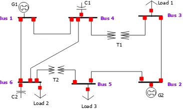
A 6-bus Ward-Hale system is used for testing the proposed
algorithm. Fig. 4 shows this system. Table 1 shows the name and
values of controlling and dependent variables in system. Table 2
is brought for loading this network. Loads written in table 2 are
the loads of 4 intervals said before [4,6].
Continuous Variable Constraint
Discrete Variable Constraint
Power Flow Constraint
(2)
(1)
[image:3.595.383.538.135.243.2]Fig. 1- TSC & TCR combination
Fig. 2- reactor voltage for β=100
Fig. 3- capacitor voltage for α=20
(3)
Poweloss Nbus
i
Vbusi
Fitness
: 1 G1 G2C1 Load 1
C2 Load 2
Load 3
Bus 1 Bus 4 Bus 3
Bus 2 Bus 5
Bus 6
T1
[image:3.595.330.513.674.783.2]Fig. 4- Ward-Hale system TABLE 1
CONTROLLING VARIABLES AND DEPENDENT VARIABLES
Limits Control Variables Limits Dependent Variables High Low High Low 1.1 1 Vg1(P.U.) 100 -20 Qg1(MVar) 1.15 1.1 Vg2(P.U.) 100 -20 Qg2(MVar) 15 0 Qc1(MW) 1.05 0.95 V3(P.U.) 30 0 Qc2(MW) 1.05 0.95 V4(P.U.) 1.02 0.98 T1(Ratio) 1.05 0.95 V5(P.U.) 1.02 0.98 T2(Ratio) 1.05 0.95 V6(P.U.) TABLE 2 LOAD VARIABLES MVar
(MVar 4 Q ) (MW 4 P ) (MVar 3 Q ) (MW) 3 P (MVar 2 Q ) (MW 2 P ) (MVar 1 Q ) (MW 1 P ) Bu s 0 0 0 0 0 0 0 0 1 0 0 0 0 0 0 0 0 2 9.9 49.5 13.75 68.7 5 16.5 82.5 12.1 60.5 3 0 0 0 0 0 0 0 0 4 16.2 27 22.5 37.5 27 45 19.8 33 5 9 45 12.5 62.5 15 75 11 55 6
Obtained voltages from load flow for considered loads are
according to table 3. In this load flow V
gis set in middle of its
[image:4.595.327.535.176.480.2]range.
TABLE 3
VALUE OF VARIABLE AFTER LOAD FLOW
Load 2
P(MW) Q(MVar) V(p.u) Load 1
P(MW) Q(MVar) V(p.u) Bus 1.05 138.36 191.9 1.05 55.468 112.07 1 1.105 74.235 50 1.105 34.948 50 2 0.77067 0 0 0.90805 0 0 3 0.78019 0 0 0.9204 0 0 4 0.73041 0 0 0.88092 0 0 5 0.71777 0 0 0.88961 0 0 6 154.09 39.402 47.516 13.566 Loss Load 4
P(MW) Q(MVar) V(p.u) Load 3
P(MW) Q(MVar) V(p.u) Bus 1.05 38.452 80.595 1.05 74.192 137.64 1 1.105 24.96 50 1.105 44.647 50 2 0.94199 0 0 0.8745 0 0 3 0.95443 0 0 0.88648 0 0 4 0.9209 0 0 0.8428 0 0 5 0.93244 0 0 0.84761 0 0 6 28.312 9.0948 70.089 18.889 Loss
Optimization for every interval is done independently.
Controlling variables and dependent variables are shown in table
4.
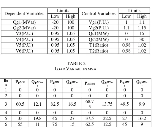
For a system with a fix capacitor, using the obtained data that
minimize THD from previous stage, a neural network is trained
and this network is used to obtain β and α is obtained from THD
minimization in two cases; α=180 for negative requested power
and
α=0 for positive requested power.
For example α and β are
shown for specific requested powers of -5MVar in table 5 [24].
TABLE 4
VALUE OF CONTROLLING AND DEPENDING VARIABLE AFTER OPTIMIZATION
Load 2 Load 1
Variable Before
ORPF ORPF Before ORPF ORPF 1.05 1 1.05 1.099 Vg1(P.U.) 1.105 1.139 1.105 1.135 Vg2(P.U.) 0.77067 1.01 0.90805 0.987 V3(P.U.) 0.78019 1.02 0.9204 1.00 V4(P.U.) 0.73041 0.98 0.88092 0.963 V5(P.U.) 0.71777 1 0.88961 0.989 V6(P.U.) 1 1 1 1 T1(Ratio) 1 1 1 1 T2(Ratio) 0 20 0 20 Qc1(MVar) 0 0 0 5 Qc2(Mvar) 39.402 13.111822 13.566 10.482789 Loss(MW) Load 4 Load 3
Variable Before
ORPF ORPF Before ORPF ORPF 1.05 1.097 1.05 1.099 Vg1(P.U.) 1.105 1.149 1.105 1.148 Vg2(P.U.) 0.94199 1.02 0.8745 0.958 V3(P.U.) 0.95443 1.04 0.88648 0.972 V4(P.U.) 0.9209 1.03 0.8428 0.956 V5(P.U.) 0.93244 1.04 0.84761 0.962 V6(P.U.) 1 .98 1 .98 T1(Ratio) 1 1 1 1 T2(Ratio) 0 15 0 5 Qc1(MVar) 0 5 0 5 Qc2(Mvar) 9.0948 7.0064093 18.889 13.963364 Loss(MW) TABLE 5
α AND β VALUES FOR REQUESTED REACTIVE POWER OF -5MVar
α β THD Q
82.5 91.5 3.5985 -5.0002 90 93.5 3.6289 -5.0007 99.5 96 3.5783 -4.9945 105.5 97.5 3.4961 -5.0042 112.5 99 3.3527 -4.9939 115 99.5 3.2885 -5.0013 117.5 100 3.2179 -4.998
137 102.5 2.4765 -4.9983 144.5 103 2.106 -4.9995 169.5 103.5 0.66205 -4.9912
170 103.5 0.63215 -4.9914
171 103.5 0.56472 -4.9917
171.5 103.5 0.5347 -4.9918
172.5 103.5 0.47455 -4.992
[image:4.595.47.281.448.647.2]174.5 103.5 0.34639 -4.9922
176 103.5 0.25582 -4.9923
177 103.5 0.18801 -4.9923
177.5 103.5 0.15798 -4.9923
178.5 103.5 0.098541 -4.9923
179.5 103.5 0.043002 -4.9923
[image:5.595.45.293.51.476.2]180 103.5 0.026626 -4.9923
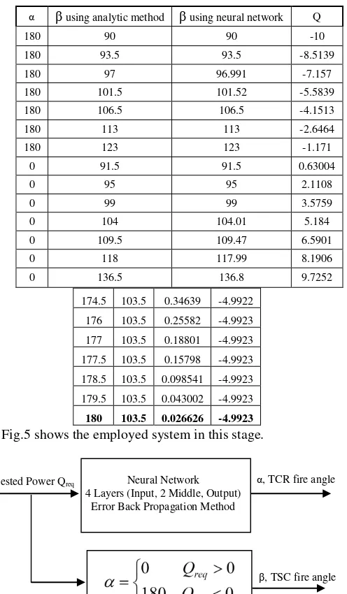
Fig.5 shows the employed system in this stage.
In second system, another neural network is trained for
determination of β and number of capacitor banks. From
previous discussion, minimum THD takes place in cases that
α=0 and α=180. Considering this fact in case of existing a
capacitor α=0. Fig. 6 shows the construction of the neural
network and its outputs in case of existence of a bank. It should
be said that because of the discrete nature of n, it should be
rounded. For example, table 5 and 6 show the outputs of neural
network for both systems.
Table 5
COMPARITION OF AND OBTAINED FROM NEURAL NETWORK AND ANALYTIC
[image:5.595.323.563.180.344.2]METHOD
Table 6
β AND N VALUE OBTAINED FROM ANN FOR A REQUESTED REACTIVE POWER AND
COMPARING IT WITH ANALYTIC METHOD OUTPUT
VI.
CONCLUSIONIt should be mentioned that discrete amounts in this paper as
their natures are considered discrete variables in all stages of
investigation.
In case of existing only one capacitor, if requested reactive
power is positive, capacitor should be switched and β should be
determined for minimizing the THD, and if requested reactive
power is negative, capacitor shouldn’t be switched on and β
should be calculated for minimizing the THD.
And in case of existing a bank, if requested power is positive,
maximum capacitors should be switched on and β should be
determined to supply requested reactive power ,and when
requested power is negative, although reactor is needed,
maximum capacitors should be used subject to have a reactor
that by adding it to capacitor the requested reactive power is
obtained.
VII.
R
EFERENCES[1] Wei Yan Fang Liu Chung, C.Y. Wong, K.P. , "A hybrid genetic algorithm-interior point method for optimal reactive power flow", Power Systems, IEEE Transactions on, Volume: 21 , Issue: 3, p.p. 1163 – 1169, Aug. 2006
[2] Fang Liu Chung, C.Y. Wong, K.P. Wei Yan Guoyu Xu, "Hybrid Immune Genetic Method for Dynamic Reactive Power Optimization", Power System Technology, 2006. PowerCon 2006. International Conference on, P.P 1 – 6, Oct. 2006
[3] Xingong Cheng Yong Zhang Lixia Cao Jiwen Li Tao Shen Sheng Zhang , " A Real-time Hierarchical and Distributed Control Scheme for Reactive Power Optimization in Multi-area Power Systems", Transmission and Distribution Conference and Exhibition: Asia and Pacific, 2005 IEEE/PES, P.P. 1 – 6, 2005
[4] M. Rashidi-Nejad, M. H. Javidi Dasht-Bayaz, "Transition Optimization of Voltage and Reactive Power Control", 11th ICEE, May 2003, Vol. 4 [5] Javier R. O. Soto, Carlos R.R. Dornellas, Djalma M. Falcão, "Optimal
Reactive Dispatch Using a Hybrid Formulation: Genetic Algorithms and Interior Point", 2001 IEEE conference, 10th-13th September
α
β
using analytic methodβ
using neural network Q180 90 90 -10
180 93.5 93.5 -8.5139
180 97 96.991 -7.157
180 101.5 101.52 -5.5839
180 106.5 106.5 -4.1513
180 113 113 -2.6464
180 123 123 -1.171
0 91.5 91.5 0.63004
0 95 95 2.1108
0 99 99 3.5759
0 104 104.01 5.184
0 109.5 109.47 6.5901
0 118 117.99 8.1906
0 136.5 136.8 9.7252
N. cap. Analytic Method
N. cap. Neural network
β
Analytic meth.
β
ANN Q
0 -0.0221 90 90.038 -10 0 -0.0358 93.5 93.649 -8.505 0 0.2452 97 92.248 -7.1452 2 2.1266 92.5 92.508 -5.5887 3 2.905 92 92.102 -4.1295 4 3.8969 91.5 93.743 -2.6779 6 6.0037 91.5 91.613 0.65545 6 6.0285 95 94.942 2.0955 6 6.0583 99 98.953 3.574 6 5.9073 104 104.02 5.1711 6 5.9477 109.5 109.51 6.6012 6 6.0066 118 118.01 8.1935 6 6.0047 135.5 136.26 9.6894
Neural Network 4 Layers (Input, 2 Middle, Output)
Error Back Propagation Method
Requested Power Qreq α, TCR fire angle
β, TSC fire angle
Fig. 5- System employed for determining α and β For a bank of 1 capacitor
Neural Network 4 Layers (Input, 2 Middle, Output)
Error Back Propagation Method
Requested Power Qreq
Number of employed capacitor
[image:5.595.22.293.647.712.2]β, TSC fire angle
[6] S. Salamat Sharif, James H. Taylor, Eugene F. Hill, Brian Scott, Dave Daley, "Real-Time Implementation of Optimal Reactive Power Flow", IEEE Power Engineering Review, August 2000
[7] L. D. B. Terra, M. M. Gouvb Jr., "Fuzzy Goal Programming Applied to the Optimal Reactive Power Flow Problem", Electric Power Engineering, 1999. PowerTech Budapest 99. International Conference on, P.P 3410 - 3414 vol.6, 29 Aug.-2 Sept. 1999
[8] Sharif, S.S. Taylor, J.H., "Dynamic optimal reactive power flow", American Control Conference, 1998. Proceedings of the 1998, P.P 3410 - 3414 vol.6, 24-26 June 1998
[9] Q. H. Wu, J. T. Ma, "Genetic search for Optimal Reactive Power Dispatch Of Power Systems", IEEE Control conference, 1994
[10] K. H. Adbdul-Rahman, S. M. Shahidehpour, " Reactive Power Optimization Using Fuzzy Load Representation", 1993 IEEE , April 1993 [11] Yuanyuan Sun Weijie Zheng Xu, W. , " A New Method to Model the Harmonic Generation Characteristics of the Thyristor Controlled Reactors", Power Tech, 2007 IEEE Lausanne, P.P 1785 – 1790, 1-5 July 2007
[12] Hedayati, M. , "Technical specification and requirements of static VAr compensation (SVC) protection consist of TCR, TSC and combined TCR/TSC", Universities Power Engineering Conference, 2004. UPEC 2004. 39th International, P.P 261 - 264 Vol. 1, 6-8 Sept. 2004
[13] Leonardo T. G. Lima, Adam Semlyen, M. R. Iravani, ”Harmonic Domain Periodic Steady State Modeling of Power Electronics Apparatus: SVC and
TCSC”, 2003 IEEE
[14] Mehmet Uzunoglu, Celal Kocatepe, Recep Yumurtaci, Kayhan Gulez,
“The Various Operating Condition, Harmonics Effects and Stability of Thyristor Controlled Reactor”, 2000 IEEE
[15] J.G. Mayordomo, M. Izzeddine, L. Zabala, “A Contribution for Modeling Static VAr Compensators in Iterative Harmonic Analysis”, 1998 IEEE [16] Wilkosz, K. Sobierajski, M. Kwasnicki, W., "The analysis of harmonic
generation of SVC and STATCOM by EMTDC/PSCAD simulations", Harmonics and Quality of Power, 1998. Proceedings. 8th International Conference on, P.P 853 - 858 vol.2, 14-16 Oct. 1998
[17] Gutierrez, J.; Montano, J.C.; Lopez, A.; Castilla, M., " Effects of harmonic distortion of the supply voltage on the optimum performance of a thyristor controlled reactor-type compensator", Science, Measurement and Technology, IEE Proceedings, P.P 15 – 19 vol 141, Jan. 1994
[18] P.M.Anderson, A.A Fouad, Power System Control and Stability, Revised Printing, IEEE Press, 1994.
[19] Montano, J.-C.; Gutierrez, B.J.; Lopez, O.A.; Castilla, I.M., " Effects of voltage-waveform distortion in TCR-type compensators", Industrial Electronics, IEEE Transactions on, P.P 373 – 383 vol 40, June 1993 [20] L. J. Bohmann, R.H. Lasseter, “Stability and Harmonics in Thyristor
Controlled Reactors”, IEEE Trans.,Vol. PWRD-5, No.2, pp 1175-1 181, April 1991.
[21] Eggleston, J.F. , "Effects of harmonic voltage distortion on the terminals of single phase thyristor controlled reactors", Power Symposium, 1990. Proceedings of the Twenty-Second Annual North American, P.P 61 – 67, 15-16 Oct. 1990
[22] E.M. John, “Reactive Compensation Tutorial”, IEEE
[23] M.M. Begovic, A.G. Phadke," Control of Voltage Stability Using Sensitivity Analysis", IEEE
[24] Ashkaboosi, Maryam, Farnoosh Ashkaboosi, and Seyed Mehdi Nourani. "The Interaction of Cybernetics and Contemporary Economic Graphic Art as" Interactive Graphics"." (2016).
[25] Dabbaghjamanesh, M., A. Moeini, M. Ashkaboosi, P. Khazaei, and K. Mirzapalangi. "High performance control of grid connected cascaded H-Bridge active rectifier based on type II-fuzzy logic controller with low frequency modulation technique." International Journal of Electrical and Computer Engineering (IJECE) 6, no. 2 (2016): 484-494.
[26] Ashkaboosi, Maryam, Seyed Mehdi Nourani, Peyman Khazaei, Morteza Dabbaghjamanesh, and Amirhossein Moeini. "An Optimization Technique Based on Profit of Investment and Market Clearing in Wind Power Systems."American Journal of Electrical and Electronic Engineering 4, no. 3 (2016): 85-91.
[27] Rakhshan, Mohsen, Navid Vafamand, Mokhtar Shasadeghi, Morteza Dabbaghjamanesh, and Amirhossein Moeini. "Design of networked polynomial control systems with random delays: sum of squares approach."International Journal of Automation and Control 10, no. 1 (2016): 73-86.
[28] Ghaffari, Saeed, M.Ashkaboosi "Applying Hidden Markov M Recognition
Based on C." (2016).
[29] S. Mohajeryami, Z. Salami, I.N. Moghaddam, "Study of effectiveness of under-excitation limiter in dynamic modeling of Diesel Generators," Power and Energy Conference at Illinois (PECI), pp.1-5, Feb. 28 2014-March 1 2014