Parallel Implementation for Phase-Field Simulation
of Flow Effect on Dendritic Growth with GPU Acceleration
Changsheng Zhu
1,2,+, Jinfang Jia
1, Hong Zhang
1, Rongzhen Xiao
2and Li Feng
2 1College of Computer and Communication, Lanzhou University of Technology, Lanzhou 730050, China 2State Key Laboratory of New Non-ferrous Metal Materials, Lanzhou University of Technology,Lanzhou 730050, Gansu, China
A Sola-phasefield model combined Sola algorithm with phase-field model is established. It is difficult to implement real-time simulation as the computational grids increase. Taking pure SCN for example, the solidification microstructure evolution process in the presence offlow has been accelerated on a GPU with CUDA programming. The GPU implementation of the Sola-phasefield model is introduced in this paper. The acceleration results of the dendritic growth simulation underflow by using a single NVIDIA GeForece GTX780 GPU with different memories are also evaluated. The results show that the GPU computation with the shared memory achieves the best acceleration effect, which is 56.16 times faster than that on a single CPU core for 2048©2048 grid size. In addition, the simulation results on GPU tally well with that on CPU, which indicates the reliability of GPU-accelerated phase-field simulation. [doi:10.2320/matertrans.M2014269]
(Received July 24, 2014; Accepted August 26, 2014; Published November 25, 2014)
Keywords: phase-field model, Sola algorithm,flow, dendritic growth, graphic processing unit (GPU)
1. Introduction
From a macro point of view, crystal growth is actually a transportation process of heat, mass and momentum. The transportation process plays a limited role in crystal growth rate and affects the growth interface stability.1)There exists a
natural convection caused by temperature difference and concentration difference besides the momentum convection in melt convection during solidification process. The natural convection is always present in the melt solidification process, which has an important influence on the structure and composition segregation after solidification,2) and
directly affects the solidification defect distributions of solute segregation, solidification porosity and cavity. Therefore, the study on theflow effect during microstructure solidification is of great significance.
In recent years, research on microstructure formation rule under convection using computer simulation technology is one of the research focuses and frontier topics in the microstructure solidification research field. Traditional den-dritic growth simulation based on sharp interface model must accurately track complex solid-liquid interface, and the calculation is difficult. However, phase-field method not only avoids the real-time tracking for boundary, but does not need to judge the explicit boundary conditions repeatedly. Thus, the phase-field method has become a computing tool used to simulate complex graphics causes in the crystal growth process.35)With the development of computational science,
the melt convection is gradually coupled into microstructure simulations.611)As phase-field method is applied more and more widely in solidification microstructure simulation, the established phase-field model is more and more complicated. Large-scale simulation is required to realize the actual casting microstructure simulation, which makes the calculation amount is a prominent bottleneck by using finite difference method. So, adopting reasonable and efficient numerical solution method for phase-field model is very important.
Some studies in this respect have been carried out by scholars. LINet al.12)simulated the three-dimensional phase-field model of dendritic crystal growth with high anisotropy using an adaptive mesh method. DHOTE et al.13) imple-mented the phase-field models for shape memory alloys using distributed computing, and the numerical implementa-tion is based on the isogeometric analysis framework. JELINEKet al.14)simulated an extremely lattice Boltzmann
(LB)-cellular automation (CA) model of two-dimensional dendritic solidification under forced convection using MPI technique. GUO et al.15) studied alloy dendrite growth
during solidification with coupled thermal-solute-convection fields using a novel parallel-multigrid numerical approach. Yamanaka et al.16) implemented the three-dimensional phase-field simulation for dendritic solidification of a binary alloy on a single NVIDIA Tesla C1060 GPU, the simulation results showed that the GPU calculation for 5763 computa-tional grids is 100 times faster than that with a single CPU core under the same conditions. Takaki et al.17) performed very-large-scale phase-field computations by a GPU super-computer, and showed the survival of unfavorably oriented dendrites and highly complicated dendrite-dendrite interac-tions in three-dimensional space during the directional solidification of a binary alloy.
In this paper, the correctional Sola algorithm using adaptive pressure iteration method combine with the phase-field model to establish a Sola-phase field model of undercooled melt dendrite growth under flow. In the numerical simulation, it is time-consuming to iteratively solve the pressure field, and difficult to meet real-time requirements when the computational scale increases. Hence, study on how to improve the speed of solving the pressure equation becomes a very important issue.18) For phase-field model, due to the adoption of uniform grids and the equations with good parallelism, it is suitable for using the GPU and CUDA to realize parallel solution to phase-field simulation, with the purpose of shortening computation time and improving computational efficiency.
2. Phase-Field Model
2.1 Phase-field equation and temperaturefield equation The phase-field and temperaturefield controlling equations coupling with thermal noise can be defined as1)
¸ð*nÞ@tº¼ ½ºuð1º2Þð1º2Þ þ r½W2ðn *
Þrº
þ X
m¼x;y
@m jrºj2Wð~nÞ@Wð~nÞ @ð@xºÞ
ð1Þ
@tuþ ð1¼ÞVru¼Dr2uþ 1
2@tº r *
*qð*r; tÞ ð2Þ
jVj ¼ ffiffiffiffiffiffiffiffiffiffiffiffiffiffiffiffiffiffiffiffiffiffiffiV0x2þV0y2
p
ð3Þ
where º is the phase field variable; is coupling constant. The dimensionless temperature u is defined as u¼ ðT TMÞ=ðL=CpÞ, where TM, L and Cp are the melting
temperature, latent heat and specific heat, respectively.¼can be viewed as a solid fraction:¼¼ ð1þºÞ=2,¼2 ½0;1.V0x2
andV0y2are the dimensional variables of melt inflow velocity
along directions x and y, respectively. Their dimensionless forms are: V0xd0=D!Vx,V0yd0=D!Vy, whered0 is the
capillary length.Dis the thermal diffusivity.¸and Ware the interface kinetics anisotropy and the interface energy anisotropy, both of them are functions of interfacial normal vector ~n.¸and Ware defined as
¸ð*nÞ ¼¸0 1þ14¾43¾ 4
ð@xºÞ4þ ð@yºÞ4 jrºj4
ð4Þ
Wð*nÞ ¼W0ð13¾4Þ 1þ14¾34¾ 4
ð@xºÞ4þ ð@yºÞ4 jrºj4
ð5Þ
where ¸0 and W0 are the temporal scale and spatial scale,
respectively. ¾4 is the anisotropy strength of the surface energy.
~q is the thermal noise vector, and follows the Gaussian distribution, defined as
hqmð*r; tÞqnð*r0; t0Þi ¼2DkBCpT 2
m L2 ¤mn¤ðr
*
*r0Þ¤ðtt0Þ ð6Þ
where *r and *r0 are position vectors; t and tA are time variables. kB is the Boltzmann constant; ¤mn is Kronecker function; ¤ is the delta function. Some variables can be converted into their dimensionless forms as: *r =W0!*r,
t=¸!t,D¸0=W02!D,*q¸0=W0!*q,W0 and ¸0are the
length scale and time scale, and then the thermal noise vectors are given by
hqmð*r; tÞqnð*r0; tÞi ¼2DFu¤mn¤ðr *
*r0Þ¤ðtt0Þ ð7Þ
where the thermal noise amplitudeFuis defined as
Fu¼kBT 2 MCp
L2W02 ¼
kBTM2Cp
L2d02 d0
W0
2
¼Fexp Wd0 0 2
ð8Þ
2.2 Mass and momentum conservation equations The mass conservation equation and momentum equation are coupled to the phase-field equation in the following way. To describe the liquid melt flow between liquid phase region and dendrite, assuming that the flow in solidification process does not cause the grain position change.1)
The mass conservation equation is given by
r ðð1ºÞV~Þ ¼0 ð9Þ
whereV*is the velocity vector.
The momentum conservation equation can be defined as
@
@t½ð1ºÞV~ þV~ð1ºÞ rV~ ¼ 1
μð1ºÞrPþ r½®rð1ºÞV~ m ~V ð10Þ
where μ, ® and P are the density, kinematic viscosity and dimensionless pressure, respectively. Here, assuming the solid and liquid phase densities are the same. The term m
stands for interfacial drag coefficient and is given by
m¼h®º
2ð1ºÞ
W2 ð11Þ
where h is the dimensionless constant between 2.55³2.757 related to the interface thickness.
3. Initial Condition and Simulation Parameters
For an initial nucleus of the radius r0, all the initial
conditions are shown as follows:
º¼1 u¼0 Vx¼0
Vy¼0 P¼0 x2þy2r20
º¼ 1 u¼ Vx¼0
Vy¼U P¼0 x2þy2> r20
8 > > > < > > > :
ð12Þ
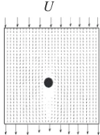
wherexandyare the coordinate axes. The initial interface is defined as a round area at the center of the computational domain and standing for the initial nucleus. Undercooled melt enters the domain from the top boundary with a uniform velocity U, and exits at the bottom boundary. The initial condition of simulation domain is shown as Fig. 1.
The pure SCN is employed as research object in this paper. The physical properties of SCN and the computational parameters are listed in Table 1.
4. Introduction to SOLA Algorithm, GPU and CUDA
4.1 Brief introduction to SOLA algorithm
Numerical simulation of thefilling process is an advanced
U
[image:2.595.390.462.72.169.2]Fig. 1 The initial condition of simulation domain.
Table 1 The physical parameters of SCN and computational parameters. L/(J·kg¹1) μ/(kg·m¹3) cp/(J·kg¹1·K¹1) Tm/K d0/W0 "
46.250 1.02 2.000 331.100 0.139 0.55 ¾ D ¦x=¦y ¸0 ¦t
[image:2.595.58.289.373.427.2]technique in the casting field. Many domestic and foreign researchers have explored a variety of numerical computation methods for flow field simulation in casting filling process, such as the SIMPLE method and MAC method. The SOLA (Solution Algorithm) method is another iterative method proposed by American Los Alamos laboratory researchers to solve the pressurefield and velocityfield. Because the SOLA algorithm only needs to iterate the pressurefield, which has high efficiency, so the SOLA algorithm is chosen in this paper. The steps to solve the pressurefield and velocityfield with SOLA algorithm are as follows:
(1) On the basis of the initial conditions or the last moment’s values, try to calculate the new moment’s estimated values of the velocity field by the momentum equation.
(2) In order to satisfy the continuity equation, namely the mass conservation equation, the pressure must be corrected iteratively. And then the new updated velocity is obtained by the corrected pressure. The pressure will be iterated repeatedly until the convergence condition is satisfied.
4.2 Brief introduction to GPU and CUDA
Driven by the market demand and large scale scientific computing, the programmable Graphic Processing Unit (GPU) has evolved into a highly parallel, multithreaded, manycore processor with tremendous computing power and very high memory bandwidth.19)Thefloating-point
perform-ance and memory bandwidth of the GPU are higher than that of the contemporaneous CPU.
Introduced by NVIDIA in 2006, CUDA is a general purpose parallel computing platform and programming model that regards GPUs as data parallel computing devices to solve many complex computational problems in a more efficiency way than on a CPU.19) CUDA comes with a
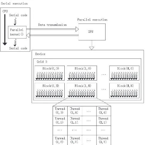
software environment that allows developers to use C as a high-level programming language. The CUDA programming model assumes a system composed of a host and a device, each with their own separate memory, where the CPU is the host and the GPU is the device. The CPU and GPU work together using the heterogeneous model. Figure 2 shows the work mode of CPU+GPU heterogeneous model.
CUDA threads may access data from multiple memory spaces during their executions. Each thread has private local memory. Each thread block has a shared memory visible to all threads of the block and with the same lifetime as the block. All threads have access to the same global memory. There are also two additional read-only memory spaces accessible by all threads: the constant and texture memory spaces. The global, constant and texture memory spaces are optimized for different memory usages. It is necessary to use them reasonably according to the specific application to improve program performance.
5. The Parallel Implementation of Sola-Phase Field Model on GPU
5.1 Algorithm design and parallel computing process For the phase-field model solution, the computations of different grid points are data independent at the same time step, and the computations for each grid point are the same.
So, the numerical solutions to the whole computational domain meet data parallelism requirement, the computations for eqs. (1), (2), (9) and (10) can be executed on GPU to improve the algorithm’s running speed. Because the data are stored in global memory with the access latency of hundreds to thousands of cycles, and a large number of non-linear memory accesses exist by usingfinite difference method, the bottleneck of affecting program performance is memory access rather than computation. In this paper, the efficient shared memory (the shared memory latency is almost 1/100 of the global memory latency20)) is employed to achieve coalescent access, and improve memory access speed through copying data from global memory to shared memory only once before parallel computing. In addition, the GPU computations using global memory only and texture memory are also done. When the calculation data are all stored in global memory, any data reading in computation process will access global memory, which spends much time on memory access, resulting in low computational efficiency. When using texture memory in global memory, the original reading data from global memory becomes obtained from texture memory, which is a read-only memory, uses data locality by cache and has a good acceleration effect on mass data’s non-aligned accesses. In kernel, the texture memory is accessed by invoking texture fetching function. The fetched texture memory must be bound to a certain area of global memory before starting the kernel. On the computational domain boundaries, the slip boundary condition is used forflowfield, and the Zero-Neumann boundary condition is applied to phase-field and temperaturefield.21)
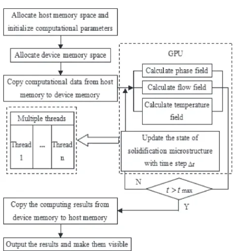
The parallel computing process for Sola-phasefield model based on GPU is shown in Fig. 3:
Step 1: Allocate host memory space and device memory space, and initialize computational parameters on the host.
Step 2: Copy computational data from host memory to device memory.
[image:3.595.307.549.68.311.2]Step 3: Calculate the phase-field value at each grid point on GPU.
Step 4: Correct pressurefield by using Sola method, and then the correctional pressure value is substituted into eq. (10) to obtain the velocityfield.
Step 5: Calculate the temperature field coupled withflow field.
Step 6: Repeat step 3 as the time step increases ¦t to update microstructure solidification state until the end of the cycle time step.
Step 7: Copy the computing results from device memory to host memory, output the results and make them visible.
5.2 Program optimization
(1) Computational domain partition. The computational domain can be divided into several small areas according to the CUDA thread hierarchy. A thread block is responsible for the computation of a small area, and each thread in thread block is responsible for a mesh point computing in small area. However, the GPU Stream Multiprocessors (SMs) create, manage, scheduling and execute threads with 32 parallel threads (warp) as a group, as shown in Fig. 4. The data dependences with adjacent threads exist in the computations of the boundary threads in a thread block. Therefore, it is necessary to obtain a ghost cell22)to store data required by boundary threads. For the processed data in a block, the internal data meet coalesced memory access while the data on left and right boundaries need special treatment. Within the permissible range, the larger the blockDim.x is, the smaller the proportion of the data needing special treatment is, which is beneficial to improve program performance. Generally, the number of threads in a thread block is within [128, 256] as a multiple of 32. After testing, the program achieves the optimal performance when the thread block dimension is (128, 1, 1).
(2) Data transmission between the CPU and GPU. In the program, except copying computational data from host memory to device memory before parallel computing, copying computing results from device memory to host memory after completing computation, and being required to output the results at specific time step, GPU is responsible for all the computations of each iteration, in which data exchange with the CPU is not required. In addition, allocating host memory through pinned memory can achieve higher data transmission bandwidth between host memory and device memory.
(3) Global memory access optimization. In order to reduce the use of global memory, the shared memory located in the GPU chip is employed in program to process data. Thus, repeated reading to the overlapping mesh point data from global memory is avoided, and the data reading speed is accelerated. Meanwhile, the non-coalesced access to global memory caused by using difference method is greatly decreased.
6. Simulation Results and Discussions
The simulation platforms are Intel(R) Xeon(R) CPU E5405 @2.00GHz 2.00GHz with 4.00GB RAM and a single NVIDIA GeForce GTX 780 GPU using CUDA 5.0 on Windows 7 operating system.
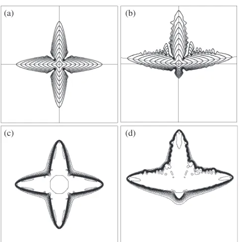
6.1 Dendrite growth evolution process underflow Figures 5(a)³(b) show the dendritic growth morphology evolution processes when flow velocity U=0 (without thermal noise) and U=0.32 (with thermal noise) for times up to8600t, the time difference between contours is900t
with the grid size 1024©1024. It can be seen that flow changes dendritic growth symmetry, namely, the length of the upstream main dendrite arm is longer than that of the downstream’s, and the main dendrite arms perpendicular to flow direction grow inclining to the upstream direction. Because the undercooled meltflow takes away the latent heat released during the upstream dendrite solidification, with the downstream latent heat being not easy to spread, which makes the actual undercooling of the upstream dendritic tip greater than the downstream undercooling, and the larger undercooling is more beneficial to dendritic growth. Besides, the temperature field boundary layer thickness of the upstream dendrite tip is thinner than that of the downstream Fig. 3 Parallel computing process of Sola-phasefield model on GPU.
[image:4.595.50.287.63.317.2] [image:4.595.309.544.71.220.2]dendrite tip and the upstream dendritic temperature boundary layer thickness vertical to the flow direction is also thinner than the downstream’s. The temperature fields correspond-ing to Fig. 5(a)³(b) when t¼8600t are shown in Fig. 5(c)³(d).
6.2 Parallel efficiency
In order to study the acceleration effect of the phase-field simulation by utilizing the shared memory, the GPU-based simulations are performed with different memories. Figure 6 shows the computation time at 3000 time steps for different computational domain on a single CPU core and a single GPU by using different memories, where G represents Global Memory; T represents Texture Memory; S represents Shared Memory. The line graph of the speedup compared to the CPU computation is shown in Fig. 7. It can be seen that the computing performance has improved greatly no matter what kind of memory is used. The speedup increases with the grid size increases. The acceleration performance is the highest when using the shared memory, followed by the texture memory, and then the global memory. The GPU computation with the shared memory is 56.16 times faster than that by a single CPU core for 2048©2048 computational grids. This can be interpreted as: the shared memory’s access speed is very fast with only a few clock cycles, and the coalesced access is also realized, which improves the computing performance greatly. The texture memory has cache mechan-ism, in which the texture cache can pre-fetch several pixels surrounding the coordinate corresponding position. If the probability of hitting the cache is high enough, the computing performance can be better improved. However, when using the global memory, not only is the memory access cycle long, but a large number of memory access operations are also non-coalesced, which affects the computing performance im-provement.
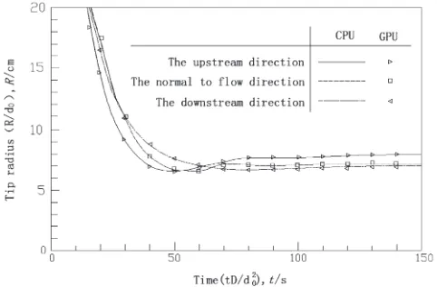
6.3 Dendritic tip velocities and tip radius comparisons between CPU and GPU computation
The dendritic tip velocities and tip radius of the upstream direction, the normal to flow direction and the downstream direction change with time are quantitatively compared between CPU and GPU computation under forced flow, as shown in Fig. 8 and Fig. 9. It can be seen that the tip velocities and tip radius based on GPU computation are in good agreement with the simulated values on CPU. In the initial stage of dendrite growth, all directions’tip velocities and tip radius are larger. With the dendritic growth, the frontier undercooling of dendritic tip decreases rapidly because a large amount of latent heat is released in the solidification process. And then each dendrite tip achieves different stable undercooling, with the tip velocities and tip radius reaching a steady state.
7. Conclusions
(1) A Sola-phasefield model combined Sola algorithm with phase-field model is established in this paper. And the GPU-accelerated Sola-phase field simulation is imple-mented.
(2) The results show that the single GPU computation by utilizing the shared memory reflects the best accel-eration performance with a maximum speedup of 56.16, which makes it possible to achieve an efficient phase-field simulation to some extent on a single computer.
(c)
(a) (b)
(d)
Fig. 5 Dendritic growth morphology evolution processes and temperature fields when t¼8600t. (a)(c) U=0 (without thermal noise), (b)(d) U=0.32 (with thermal noise).
Fig. 6 CPU and GPU computation time for different computational grids.
[image:5.595.49.291.66.310.2] [image:5.595.324.528.71.214.2] [image:5.595.332.521.252.394.2](3) The dendritic tip velocities and tip radius calculated on GPU are in good agreement with that on CPU, which demonstrates the reliability of the parallel computing method for Sola-phasefield simulation based on GPU.
Acknowledgments
This Project is Supported by the National Natural Science Foundation of China (51161011, 11364024), the
Key Technology R&D Program of Gansu province (1204GKCA065), the Fundamental Research Funds for the Universities of Gansu province (201210) and the Funds for Distinguished Young Scientists of Lanzhou University of Technology (J201304).
REFERENCES
1) X. Tong, C. Beckermann and A. Karma:Phys. Rev. E61(2000) R49 52.
2) J.-H. Jeong, N. Goldenfeld and J. A. Dantzig:Phys. Rev. E64(2001) 041602.
3) J. J. Li, Z. J. Wang, Y. Q. Wang and J. C. Wang:Acta Mater.60(2012) 14781493.
4) M. Berghoff, M. Selzer and B. Nestler: Sci. World J. 2013(2013) 564272.
5) Y. Shibuta, K. Oguchi and M. Ohno:Scr. Mater.86(2014) 2023.
6) Y. Sun and C. Beckermann:Phys. D237(2008) 30893098.
7) Y. J. Chen and C. L. Chen:Acta Phys. Sin.57(2008) 45854589.
8) X. F. Yuan, Y. T. Ding, T. B. Guo and Y. Hu: Chin. J. Nonfer. Met.20 (2010) 14741480.
9) Z. Chen, L. M. Hao and C. L. Chen:J. Cent. South Univ. Technol.18
(2011) 17801788.
10) H. Barati, M. R. Aboutalebi and S. G. Shabestari:Canad. Metall. Q.50
(2011) 408415.
11) J. W. Wang, Z. P. Wang, Y. Lu, C. S. Zhu, L. Feng and R. Z. Xiao:
Trans. Nonfer. Met. Soc. Chin.22(2012) 391397.
12) H. K. Lin, C. C. Chen and C. W. Lan:J. Cryst. Growth318(2011) 51 54.
13) R. Dhote, H. Gomez, R. Melnik and J. Zu:Proced. Comp. Sci. 18
(2013) 10681076.
14) B. Jelinek, M. Eshraghi, S. Felicelli and J. F. Peters: Comp. Phys. Commun.185(2014) 939947.
15) Z. Guo, J. Mi, S. Xiong and P. S. Grant:J. Comput. Phys.257(2014) 278297.
16) A. Yamanaka, T. Aoki, S. Ogawa and T. Takaki:J. Cryst. Growth318
(2011) 4045.
17) T. Takaki, T. Shimokawabe, M. Ohno, A. Yamanaka and T. Aoki:
J. Cryst. Growth382(2013) 2125.
18) T. Jing:Numerical Simulation of Solidification Process, (Publishing House of Electronics Industry, Beijing, 2002) p. 60.
19) NVIDIA CUDA C Programming Guide version 5.0. http://docs. nvidia.com/cuda/index.html, (cited 2014-4-24).
20) S. Zhang, Y. L. Zhu, K. Y. Zhao and Y. B. Zhang: GPU High Performance Computing of CUDA, (China Water & Power Press, Beijing, 2009) p. 160.
21) J. W. Wang, C. S. Zhu, Z. P. Wang, L. Feng and R. Z. Xiao:Trans. Nonfer. Met. Soc. Chin.21(2011) 16201626.
22) MICIKEVICIUS P. 3D Finite Difference Computation on GPUs using CUDA. http://www.doc88.com/p-186718445840.html, (cited 2014-4-25).
Fig. 9 Dendritic tip radius comparison between CPU and GPU compu-tation.
[image:6.595.48.289.68.230.2] [image:6.595.49.290.279.437.2]