Discharge-Charge Property of Lead-Acid Battery Using Nano-Scale PbO
2as Cathode Active Material
Masami Taguchi
+1, Toshihiro Sasaki
+2and Hiroki Takahashi
Department of Materials Science and Engineering, Graduate School of Engineering and Resource Science, Akita University, Akita 010-8502, Japan
In this study, nanoscale PbO2was obtained by the hydrolysis reaction of Pb(CH3COO)4in an ethanol solution, and the conventional PbO2 was prepared by the electrolytic oxidation of PbO powder in a H2SO4solution. The former PbO2was identified as single phase¢-PbO2with the average crystallite size of about 12 nm that had an excellent electrochemical activity, whereas the latter one was a mixture of¡-PbO2,¢-PbO2and PbSO4of about 41 nm average size. A hybrid lead-acid battery cathode consisting of an inner layer of the conventional PbO2and an outer layer of the nanoscale PbO2was also manufactured. The average diameter of the pores in the hybrid cathode was smaller than that of the conventional cathode of the lead-acid battery, which was made from only the conventional PbO2. The mass change in the hybrid cathode during the discharge-charge cycle test was relatively high as compared to that of the conventional cathode. Moreover, the cycle tests clearly showed that the reversibility of the discharge-charge reaction was improved in the hybrid cathode since the electrode mass returned to zero even after repeated charge and discharge. As a result, the hybrid cathode was significantly better than the conventional cathode regarding both the current efficiency and the utilization factor of the active materials of the cathode during the discharge-charge reaction. These results may suggest the manufacturing of a novel lead-acid battery with a higher power density and higher capacity. [doi:10.2320/matertrans.M2013343]
(Received September 6, 2013; Accepted November 15, 2013; Published December 28, 2013)
Keywords: lead-acid battery, cathode, nanoscale PbO2, hydrolysis, discharge-charge reaction
1. Introduction
Lead-acid batteries are superior in that they are signifi -cantly less expensive in comparison to other rechargeable batteries and can operate for a long period. As a result, the batteries are used as the power supply for starting almost all the cars around the world.1)However, a higher power density
and higher capacity lead-acid battery has become increas-ingly demanded by customers, especially the automobile industries. In recent years, the lead-acid batteries in cars also power various devices which provide a comfortable ride.
Moreover, the application fields of these batteries have
expended to the electric power storage for solar cells or wind power generation.2)In these applications, the maintenance of the discharge-charge performance over a long period of time is very important. Under the present circumstances, it seems that the development of an innovative product is needed as well as a detailed analysis of the discharge-charge reaction of the lead-acid battery.3,4)
A previous study using the electrochemical QCM method clearly showed that the discharge-charge property of the lead-acid battery is strongly affected by the discharge-charge reversibility of the PbO2as the cathode active material.57)In
the present manufacturing of the lead-acid battery, the active cathode material, PbO2, is obtained by electrolytic oxidation
using PbO powder as the starting material. However, the oxidation products are aggregations with about 10 µm diameter and sometimes contain unreacted compounds such
as PbSO4. A number of reports also indicated that the
unreacted compounds limit the discharge-charge rate and lower the capacity of the lead-acid battery. In addition, the
studies regarding the manufacturing method of a fine oxide
powder from an organic compound are now popular. By adopting a new method, there is a good chance of
successfully manufacturing nanoscale PbO2 as a single
phase. For example, Iwasaki et al.8) prepared nanoscale
anatase-type TiO2 by the hydrolysis of titanium oxysulfate,
TiOSO4·5H2O, in an alcohol solution and reported that the
particle size and the specific surface area of the hydrolysis product are affected by the type and concentration of the alcohol.
In this study, the nanoscale PbO2 was prepared by
hydrolysis in an alcohol solution and its potential as a cathode active material of the lead-acid battery was
investigated. To be more precise, the nanoscale PbO2 was
prepared by the hydrolysis of lead acetate, Pb(CH3COO)4,
in an ethanol solution and its reactivity in a H2SO4solution
was investigatedfirst. Next, several types of novel cathodes
containing the nanoscale PbO2, such as a hybrid cathode,
were manufactured and the discharge test at C/5 A and the
discharge-charge cycle test were carried out. In these tests, the current efficiency and the utilization factor of the cathode active material during the discharge-charge process were evaluated by an in-situ gravimetry analysis of the electrode mass and the data were compared with those of the
conventional cathode using the conventional PbO2 prepared
by the electrolytic oxidation of PbO powder.
2. Experimental Method
2.1 Preparation of cathode active material
Lead dioxide, PbO2 as the cathode active material of
the lead-acid battery was prepared by hydrolysis at room
temperature.9,10) Six grams of Pb(CH3COO)4 (Ardrich,
Purity: 99.5%) was placed in a mixed solution containing
3 mL of distilled water and 27 mL of ethanol and the solution was stirred by an ultrasonic homogenizer for 5 min. By this operation, the hydrolysis reaction probably proceeded as follows:
PbðCH3COOÞ4þ2H2O!PbO2þ4CH3COOH ð1Þ
+1Corresponding author, E-mail: taguchi@ipc.akita-u.ac.jp +2Graduate Student, Akita University
current were 45 kV and 200 mA, respectively. Moreover, the
microstructure of the PbO2 was observed by SEM (JEOL,
JEM-2010) and the specific surface area was measured by the BET method (YUASA-IONICS, Monosorp).
2.2 Evaluation of reactivity of PbO2 in H2SO4solution
For the nanoscale PbO2 and conventional PbO2, their
reactivities were evaluated in a H2SO4 solution. A 5.0 g
sample of the nanoscale PbO2or the conventional PbO2was
immersed in a 4.5 kmol m¹3H2SO4solution and the solution
was stirred for 60, 120, or 240 min by an ultrasonic homogenizer. After filtering the solution, the filter cake or the precipitate was washed and dried. The dried precipitate
was quantitatively analyzed by XRD. The amounts of PbO2
and PbSO4 in the precipitate were then calculated by the
Reference Intensity Ratio (RIR) method using the intensity of the diffraction pattern. In the RIR method, the calibration curve was previously produced from standard samples
composed of high purity PbO2 and PbSO4. The amount of
produced PbSO4 in the unknown sample was calculated on
the basis of the calibration curve, and the reactivities of
both the nanoscale PbO2 and the conventional PbO2 were
evaluated.
2.3 Preparation of lead-acid battery cathode
Three kinds of lead-acid battery cathodes, namely, the
cathodes with the active material of (1) 100% nanoscale
PbO2, (2) 10% nanoscale PbO2+90% conventional PbO2,
and (3) 100% conventional PbO2 were prepared, and their
discharge properties were evaluated. For the active material of (2) 10%nanoscale PbO2+90% conventional PbO2, 10 g
of the nanoscale PbO2 and 90 g of the conventional PbO2
were mixed with 0.15 g of PTEfiber, 15.8 g of 4.5 kmol m¹3
H2SO4solution and 8 g of distilled water to make a paste. The
paste was painted on the both sides of the Pb-based alloy grid. The volume of the painted paste including the grid was
35 mm©15 mm©4 mm. After drying, the electrode was
electrochemically oxidized to produce the lead-acid battery cathode in a 4.5 kmol m¹3H2SO4solution.
Subsequently, the hybrid cathode with the conventional PbO2as the inner layer and the nanoscale PbO2as the outer
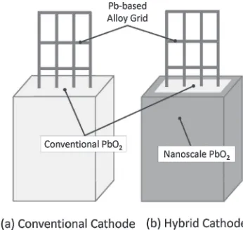
layer was manufactured, and the discharge and the discharge-charge cycle properties were examined. Figure 1 shows the structures of (a) the conventional cathode and (b) the hybrid one. For (a) the conventional cathode, the paste composed of the PbO and the H2SO4solution was painted on the Pb-based
alloy grid and the electrode was electrochemically oxidized in a H2SO4solution. This process is the same as the present
production process of cathodes in the lead-acid battery industry. On the other hand, the inner part of the active
material was the conventional PbO2 and the outer part was
covered by the nanoscale PbO2 for (b) the hybrid cathode.
Two kinds of hybrid cathodes, in which the weight ratio of
the conventional PbO2 to the nanoscale PbO2 was 1 : 1 and
1 : 2, were prepared. The pore size distribution was measured by a mercury porosity meter (THERMO ELECTRON, Pascal 140) for the conventional cathode and the hybrid cathode (1 : 1).
2.4 Discharge test and discharge-charge cycle test
Figure 2 shows the discharge-charge system using a digital microbalance. This system permits the in-situ observation of not only the electrode potential, but also the mass change in the cathode during the discharge-charge test.9,11)The sample electrode was hung from the digital microbalance by a glass hook and immersed in a 4.5 kmol m¹3H2SO4solution. A Pt
plate and an Ag/AgCl electrode were used as the counter
electrode and reference electrode, respectively. The discharge test at a current of 0.2 C was done by a potentio/galvanostat (Hokuto Denko, HZ5000) and the changes in the potential and the mass of the cathode were recorded by a computer.
Fig. 1 Schematic depiction of (a) conventional cathode and (b) hybrid cathode.
[image:2.595.339.512.70.234.2] [image:2.595.329.522.280.455.2]Moreover, a 15 cycle discharge-charge test was carried out using the same measurement system. The cycle of discharge of 202.64 mA for 3.9 ks and charge of 202.64 mA for 3.9 ks was repeated 15 times, and the potential and the mass of the cathode were in-situ measured. The current efficiency and the utilization factor of the active material were calculated from the quantity of electricity and the mass change in the cathode during the discharge-charge processes. The surface of the active material was observed by a FE-SEM (HITACHI, S-4500) after the discharge-charge test. The cross-section of the active materials was also analyzed by an EPMA (JEOL, JXA-8230) with the accelerating voltage of 15 kV and emission current of 1.0©10¹8A.
3. Results and Discussion
3.1 Crystallite size and reactivity of nanoscale PbO2 Figure 3 shows the XRD patterns of (a) the nanoscale
PbO2prepared by hydrolysis and (b) the conventional PbO2
prepared by electrolytic oxidation. For (a) the nanoscale PbO2, the product was identified as a single phase of¢-PbO2
with a tetragonal structure. On the other hand, the diffraction
peaks of orthorhombic¡-PbO2and PbSO4were observed in
addition to the ¢-PbO2 for (b) the conventional PbO2
prepared by the electrolytic oxidation of PbO as the starting material. Moreover, the diffraction peaks attributed to the
¢-PbO2 for the nanoscale PbO2 were broader than those of
the conventional PbO2. The crystallite size of the former
calculated from Scherrer’s equation was 11.6 nm, while that of the latter was 40.8 nm. TEM observations also recognized that the particle size of the nanoscale-PbO2was about 10 nm
in diameter, which was much smaller than the particle size of the conventional PbO2.
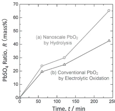
Figure 4 shows the difference in the reactivity between the
nanoscale PbO2 and the conventional one in a H2SO4
solution. It is thought that the following
dissolution-deposition reaction occurs when PbO2 is immersed in a
4.5 kmol m¹3H
2SO4solution.7,12)
PbO2þ4Hþþ2e!Pb2þþ2H2O ð2Þ
Pb2þþSO42!PbSO4 ð3Þ
After the immersion test, the reaction product was analyzed
by XRD and its PbSO4 ratio was calculated by the RIR
method. According to the XRD patterns of the reaction product, the intensity of the diffraction peak attributed to¢
-PbO2decreased with an increase in the immersion time in a
H2SO4 solution. On the other hand, the intensity of the
PbSO4increased with the increasing immersion time. There
was no significant difference in the PbSO4 ratio of the
reaction product between the nanoscale PbO2 and the
conventional one when the immersion time was short, i.e., about 60 min. However, the difference in the reactivity
between both PbO2s had gradually begun occurring with the
immersion time. Although the PbSO4 ratio of the reaction
product at 240 min was only 42 mass% for the conventional
PbO2, it was 65 mass%for the nanoscale PbO2. These results
may be related to the fact that the nanoscale PbO2is veryfine
and the constituent or the¢-PbO2has a good electrochemical
activity.13) Therefore, it can be suggested that the reaction
proceeds into the core of the nanoscale PbO2. On the other
hand, the conventional PbO2contains a certain amount of¡
-PbO2 and PbSO4 (see Fig. 3(b)). It is a matter of common
Fig. 3 XRD patterns of (a) nanoscale PbO2by hydrolysis and (b) conventional PbO2by electrolytic oxidation.
[image:3.595.147.452.69.250.2] [image:3.595.332.517.298.476.2]knowledge that ¡-PbO2 is inferior to ¢-PbO2 in the
electrochemical activity. There is a possibility that the
¡-PbO2 and the PbSO4 suppressed the reactivity of the
conventional PbO2.
3.2 Surface morphology and pore size distribution of hybrid cathode
Figure 5 shows the porosity distributions of (a) the hybrid cathode (1 : 1) and (b) the conventional one measured by the mercury porosimetry. Although the conventional cathode had two porosity volume peaks at the porosity radius of 500 and 40 nm, the hybrid cathode showed one sharp peak at 40 nm. The sharp peak may be explained by the formation of thefine pores in the outer layer of the hybrid cathode, which was never observed in the conventional cathode. In other words,
the fine pores of about 40 nm may be introduced by the
aggregation of the PbO2 particles with about 10 nm in
diameter. However, very large pores with the porosity radius
of approximately 104nm were also observed in the hybrid
cathode. This phenomenon probably reflects the detachment
between the inner layer of the conventional PbO2 and the
outer layer of the nanoscale PbO2, because the contact
between the both layers was very poor.
Moreover, the total pore volume was calculated for the hybrid cathode (1 : 1) and the conventional one. The total
pore volume of the hybrid cathode was 335.7 mm3 and
that of the conventional one was 317.0 mm3. This may be
related to the fact that the hybrid cathode has a greater
number offine pores. Thefine pores have an important role
as diffusion paths which supply the H2SO4 electrolyte to
every corner of the active material in the lead-acid battery. Therefore, it was possible that the hybrid cathode might show a higher electrolyte permeability than the conventional one, which is expected to improve the performance of the hybrid cathode.
3.3 Discharge properties of hybrid cathode
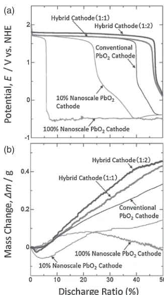
Figure 6 shows (a) the potential and (b) the mass change of various cathodes during the discharge test at a current of
0.2 C. The 0.2 C means C/5 A and the discharging takes
approximately 5 h. Among the conventional cathode, the
10% nanoscale PbO2 cathode and 100% nanoscale PbO2
cathode, all the cathodes maintained the electrode potential of 1.751.80 V vs. NHE during the initial stage of the discharge test. For the conventional cathode, the electrode potential
rapidly decreased at the discharge ratio of 40%, but was
stable at ¹0.4 V vs. NHE thereafter. The mass of the
conventional cathode also continuously increased to the
discharge ratio of 50%. This mass increase of the
conven-tional cathode may reflect the change in the active material, PbO2, to the discharge product, PbSO4:1,12)
PbO2þSO42þ4Hþþ2e!PbSO4þ2H2O ð4Þ
E¼1:6910:1182 pH0:0295pðSO42ÞV vs:NHE
For the cathodes containing the nanoscale PbO2, the decrease
in the potential started at a discharge ratio lower than 40%of the conventional cathode. In other words, the potentials of the
10%nanoscale PbO2cathode and the 100%nanoscale PbO2
cathode rapidly decreased at the discharge ratios of 24 and
6%, respectively. The mass of the 10% nanoscale PbO2
cathode decreased and then increased during the early part of discharge test, but it was suppressed at the discharge ratio of
24% or more. The increase rate of the mass of the 100%
nanoscale PbO2 cathode was lower than those of the other
cathodes and the mass started to reversely decrease near the discharge ratio of 20%. The suppression or the decrease in the mass of the cathode may suggest the reaction of the discharge product, PbSO4, to Pb:1,12)
PbSO4þ2e!PbþSO42 ð5Þ
E¼ 0:360þ0:0295pðSO42ÞV vs:NHE Fig. 5 Porosity distributions of (a) hybrid cathode (1 : 1) and (b)
conven-tional cathode.
[image:4.595.61.278.65.256.2] [image:4.595.343.506.66.359.2]Based on the potential and the mass change in the cathode during the discharge test at 0.2 C, the discharge capacities
of both the 10% nanoscale PbO2 cathode and the 100%
nanoscale PbO2 cathode were much lower than that of the
conventional cathode. This phenomenon may be caused by the passivation of the Pb-based grid as a current collector in the cathodes prepared from the nanoscale PbO2, in which
the H2SO4 electrolyte can easily diffuse through the active
material. While it is an advantage of the cathode that the
permeability of the H2SO4 electrolyte is high, it is a
disadvantage not to able to protect the Pb-based grid from corrosion.
On the other hand, the hybrid cathodes maintained a high potential for a longer time than the conventional cathode during the discharge test. In addition, it was judged from the potential change that the discharge capacity of the hybrid cathode (1 : 2) was higher than that of the hybrid cathode (1 : 1). Compared to the hybrid cathode (1 : 1), the amount of
the nanoscale PbO2 in the hybrid cathode (1 : 2) increased
about 17 percent. Moreover, the mass of the cathodes during the discharge test increased in the following order: the hybrid cathode (1 : 2)>the hybrid cathode (1 : 1)>the conven-tional cathode. Therefore, it was confirmed that the hybrid cathodes, in which the Pb-based grid as the current collector
was protected by the inner layer of the conventional PbO2
and the outer layer was coated by the nanoscale PbO2,
showed a good reactivity and a high capacity.
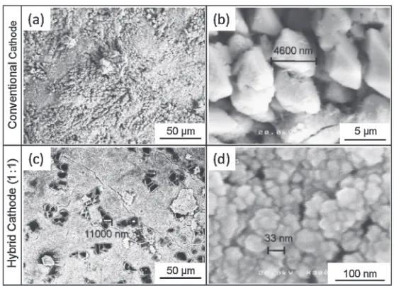
Figure 7 shows the SEM images of the conventional cathode and the hybrid cathode (1 : 1) after the 0.2 C discharge test. The surface of the conventional cathode was
heavily covered with the discharge product of PbSO4having
a grain size of about 5 µm (see (a) and (b)). On the other hand, the surface of the hybrid cathode (1 : 1) contained
fine discharge products of 2040 nm under the large PbSO4
crystals of 1020 µm (see (c) and (d)). The fine discharge
products were identified as PbSO4 by the quantitative
analysis using EPMA. Therefore, it could be considered that the high rate of the mass increase for the hybrid cathodes in Fig. 6 was caused by the excellent reactivity of the nanoscale PbO2.
3.4 Discharge-charge properties of hybrid cathode
Figure 8 shows the mass changes in the conventional cathode and the hybrid cathodes during the discharge-charge cycle test. For all the cathodes, the reaction shown in eq. (4) proceeds during discharge and the reverse reaction occurs during charge. The mass increase during discharge
corre-sponds to the mass of SO2 which is the difference between
PbSO4and PbO2. On the other hand, the charging causes the
mass decrease in connection with SO2because the discharge
product of PbSO4 returns to PbO2. For the conventional
cathode, the cycle test progressed with repeated mass increases and decreases, but there remained a mass increase of 0.14 g after the discharge-charge cycle test. The discharge
product of PbSO4 probably remained in the active material,
because the charge reaction could not be completed for the conventional cathode. On the other hand, the mass returned to zero by repeating 12 discharge-charge cycles for the hybrid cathodes (1 : 1) and (1 : 2). This means that the charge efficiency is high enough to completely restore the PbSO4to
its original state, PbO2, for the hybrid cathodes. Moreover,
the mass change of the hybrid cathode (1 : 2) during the discharge-charge process was greater than that of the hybrid cathode (1 : 1). This difference may be closely related to the
Fig. 7 SEM images of (a), (b) conventional cathode surface and (c), (d) hybrid cathode (1 : 1) one after discharge test for 5 h.
[image:5.595.159.437.68.270.2] [image:5.595.307.547.311.455.2]amount of the nanoscale PbO2in the hybrid cathode. In other
words, the hybrid cathode (1 : 2) having a higher content of
the nanoscale PbO2 showed more superior properties during
both the discharge and charge process. However, the masses of both hybrid cathodes decreased suddenly at 13 cycles. At this cycle, the peeling off of the active materials from the
hybrid cathodes was observed. The nanoscale PbO2 has a
high permeability of the H2SO4electrolyte in some ways, but
its cohesive strength is weak compared to the conventional PbO2. Therefore, the cohesive strength of the nanoscale PbO2
needs to be improved in order to prevent the peeling off of the active materials of the cathode for the product development. Figure 9 shows the current efficiency and the utilization factor of the active materials of the hybrid cathodes and the conventional cathode during the discharge-charge cycle test. The current efficiency, Ceff(%), and the utilization factor of
the active materials,U(%), were calculated by the following equation:
Ceff¼m
mo100 ð%Þ ð6Þ
where mðgÞ is the mass change of the cathode during
discharge in Fig. 8 and mo ðgÞ is the theoretical mass
change calculated by Faraday’s law using the accumulated
electric charge. The amount of PbO2converted to PbSO4by
the discharge,mPbO2!PbSO4 ðgÞ, was expressed as follows.
mPbO2!PbSO4¼m MPbO2
MSO2
ðgÞ ð7Þ
where MPbO2 and MSO2 are the molar masses of PbO2 and
SO2, respectively. Therefore, the utilization factor of the
cathode (1 : 1) were 43.9%of the discharge and 34.5%of the charge, and the values of the hybrid cathode (1 : 2) were 44.6%of the discharge and 36.1%of the charge. In addition, the utilization factors of the active materials of the con-ventional cathode during the discharge and charge were calculated to be 3.31 and 2.90%, respectively. On the other hand, the utilization factors of the hybrid cathode (1 : 1)
were 3.50% of the discharge and 3.74% of the charge, and
the values of the hybrid cathode (1 : 2) were 3.72% of the
discharge and 3.91%of the charge. Consequently, the hybrid cathode including the highest amount of the nanoscale PbO2,
or the hybrid cathode (1 : 2) showed the highest values for both the current efficiency and the utilization factor of the active materials. Therefore, it was recognized that the hybrid cathode in the lead-acid battery had a technical superiority compared to the conventional cathode. In particular, the current efficiency and the utilization factor of active materials were significantly improved using the nanoscale PbO2. The
results strongly suggest that the charge acceptability of the nanoscale PbO2was superior to that of the conventional PbO2.
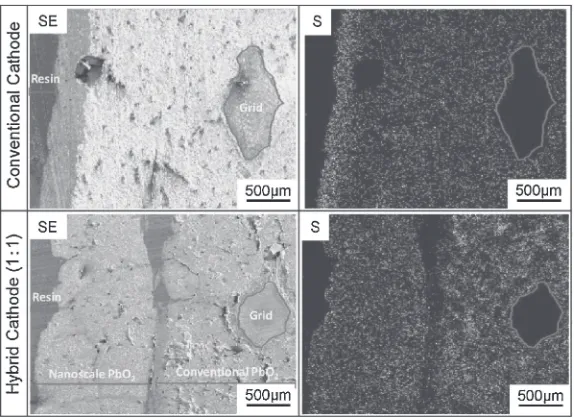
Figure 10 shows the secondary electron images and the
S K¡ specific X-ray images of the cross-sections of the
conventional cathode and the hybrid cathode (1 : 1) after the discharge-charge cycle test. There is an electrolyte/active material boundary on the left side of these images, and a Pb-based alloy grid as the current collector on the right side. For the conventional cathode, the active material was
homoge-neously filled based on the SE image of the cross-section,
which was totally smooth. On the other hand, the concen-tration of S was remarkably high near the electrolyte/active material boundary, but it drastically decreased inside the active materials. The S K¡is closely related to the discharge product of the PbSO4. Therefore, it may be postulated that the
discharge reaction of the conventional cathode was restricted to near the cathode surface. For the hybrid cathode (1 : 1), the
inner layer of the conventional PbO2 was coated with the
outer layer of the nanoscale PbO2, but the adherence of the
coating was poor. A crack was observed between the inner layer and the outer one in the SE image of the cross-section
of the hybrid cathode (1 : 1). However, the nanoscale PbO2
was changed to PbSO4over the entire outer layer. In addition,
the discharge reaction of PbO2 to PbSO4 proceeded in the
inner layer of the conventional PbO2. In other words, the
discharge reaction may be able to sufficiently proceed not
merely in the outer layer but also in the inner one of the hybrid cathode (1 : 1).
[image:6.595.100.239.69.352.2]It is necessary to consider the results of the discharge-charge cycle test in relation to the results of the pore size distribution measured by mercury porosimetry. The result
shown in Fig. 5 suggests that a large number of fine pores
were formed in the hybrid cathode (1 : 1) and thesefine pores
were able to improve the permeability of the H2SO4
electrolyte into the interior of the cathode or the active material. In addition, the inner layer, which consisted of the conventional PbO2, prevented the permeation of H2SO4
electrolyte to the current collector of the Pb-based alloy grid. Therefore, the lowering of the electrode capacity due to formation of an insulator on the surface of the current collector or the peeling off of the active materials by gas generation did not occur at the early stage, thus the hybrid cathode (1 : 1) was able to maintain a high discharge performance. Moreover, a greater part of the outer layer in the hybrid cathode (1 : 1) or the nanoscale PbO2 was useful
for the discharge-charge reaction, whereas the discharge reaction of the conventional cathode was restricted to near the electrode surface as shown in Fig. 10. Therefore, it may be concluded that the current efficiency and the utilization factor of the active materials were improved in the hybrid cathode containing the nanoscale PbO2as the active material.
4. Conclusions
Hybrid cathodes with the conventional PbO2as the inner
layer and the nanoscale PbO2 at the outer one were
manufactured, and the C/5 A discharge test and the
discharge-charge cycle test were carried out. The following conclusions were obtained based on the data from these tests. (1) The potential of the conventional cathode rapidly
decreased at about 40% of the discharge ratio during the
C/5 A discharge test. On the other hand, the hybrid cathodes (1 : 1) and (1 : 2) produced a discharge reaction to 46 and 47% of the discharge ratio, respectively. (2) The discharge-charge cycle test showed that the mass of the hybrid cathode
returned to zero after many discharge-charge cycles. More-over, the current efficiency and the utilization factor of the
active materials of the hybrid cathodes were significantly
improved compared to those of the conventional cathode. The improvement may be ascribed to the following causes;
(a) high reactivity of the nanoscale PbO2, (b) high
permeability of the H2SO4electrolyte in the outer layer and
the protection of the current collector against the attack of the electrolyte by using the conventional PbO2 in the inner
layer, and (c) high charge capability of the nanoscale PbO2,
which can thoroughly return to PbO2by charging. Therefore,
the hybrid cathodes are expected to be a novel electrode of the lead-acid battery having an excellent discharge-charge property.
REFERENCES
1) Y. Masuda and Z. Takehara: Denchi Binran 3rd Edition, (Maruzen, Tokyo, 2001) pp. 151205.
2) J. Yamaki, et al.: Handbook of Batteries, (Ohmsha, Tokyo, 2010) pp. 205297.
3) N. Hirai, K. Takeda, S. Hara, M. Shiota, Y. Yamaguchi and Y. Nakayama:J. Power Sources113(2003) 329334.
4) M. Shiota, Y. Yamaguchi, Y. Nakayama, K. Adachi, S. Taniguchi, N. Hirai and S. Hara:J. Power Sources95(2001) 203208.
5) M. Taguchi and H. Sugita:J. Power Sources109(2002) 294300. 6) M. Taguchi and H. Sugita: J. Japan Inst. Metals66(2002) 670675. 7) M. Taguchi and K. Fukui:J. Japan Inst. Metals68(2004) 887893. 8) M. Iwasaki, M. Hara and S. Ito:J. Mater. Sci. Lett.17(1998) 1769
1771.
9) M. Taguchi, K. Itou, J. Nakayama and T. Hirasawa: J. Japan Inst. Metals72(2008) 331336.
10) J. Morales, G. Petkova, M. Cruz and A. Caballero:J. Power Sources
158(2006) 831836.
11) M. Taguchi, S. Takahashi, J. Tanaka and T. Hirasawa:J. MMIJ124
(2008) 184189.
12) K. Fueki,et al.:Denkikagaku Binran 4th Edition, (Maruzen, Tokyo, 1985) pp. 428435.
[image:7.595.155.442.69.278.2]13) I. Petersson, E. Ahlberg and B. Berghult:J. Power Sources76(1998) 98105.