On the Elastic Accommodation Between the Structural Units
in the LPSO Structures
Xinfu Gu
+and Tadashi Furuhara
Institute for Materials Research, Tohoku University, Sendai 980-8577, Japan
Long range periodic stacking ordered (LPSO) structures in magnesium alloy consist of regular arrangements of four layer height fcc structural units separated by several Mg layers paralleling to the base plane. The shear transformation of the structural units from hcp structure involves large transformation strain. This strain can be significantly accommodated by the combination of the structure units with different shears. In addition, the possible lowest elastic energy configuration in both R and H type of LPSO structure is obtained. For H type LPSO structure, the opposite shear directions (or Burgers vectors of the partial dislocations) are operated in nearest structural units, while all three types of shear directions are operated successively in the nearest structural units for R type LPSO structure. This study also intends to discuss the inter spacing between the structural units in terms of the elastic interaction. It is found the elastic interaction alone cannot rationalize the spacing between the structural units. [doi:10.2320/matertrans.MAW201420]
(Received June 2, 2014; Accepted August 4, 2014; Published September 20, 2014)
Keywords: long range periodic stacking ordered structure, elastic interaction, elastic accommodation
1. Introduction
Long range periodic stacking ordered (LPSO) structures in magnesium alloy containing rear earth elements (RE) and transition elements (TM) are found to be benefit for mechanical property in both of room and elevated temper-ature.13)The LPSO structure is often consisting of regular
arrangements of four-layer high fcc structural units separated by several Mg layers paralleling to the base plane, and the structural units usually synchronize with chemical order/ enrichment of RE and TM.46)Furthermore, in recent study,
the structure unit is proposed to be consisted of TM6RE8with
L12 type short range order.7) Various LPSO structures are
found for different numbers of intermediate Mg layers and are named as 10H, 18R, 14H, and 24R when the Mg layers is 1, 2, 3 and 4 respectively.6)
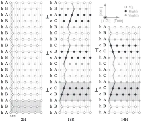
[image:1.595.306.547.309.517.2]The typical 18R and 14H LPSO structures are shown in Fig. 1 together with the HCP structure (2H) of pure magnesium. The four-layer high structure unit is marked by a filled rectangle. The stacking order change in LPSO structure can be realized by operating ah1100i=3type partial dislocations,8)which can be treated as displacive-diffusional
transformation process. The shear (displacive) process should be constrained by the surrounding matrix, and the local transformation strain field due to the shear could be significant. Thus, it is necessary to consider possible strain accommodation mechanisms associated with the LPSO structures. There are various mechanisms to accommodate the transformation strain,9) such as by diffusion mechanism
as is examined in previous study.10)It is also shown that the elastic interaction energy between structural units could be also large and serve as an another possible accommodation mechanism. In our previous study,10)the interaction between the structural units with the same or opposite shear direction is considered. However, there are three equivalent shear directions due to the crystal symmetry to achieve the same stacking order for each fcc structural units. Therefore, there would be various combinations of the shear directions to
constitute an H or R type of LPSO structure. However, the preferred shear directions or the detailed transformation mechanisms are still unknown.
In this work, the elastic interaction energy between the structural units with different shear directions will be calculated to show the low energy configuration of H or R type of LPSO structures. Furthermore, the possible inter spacing between the neighboring units will be discussed in the view of elastic interaction.
2. Calculation Method
The elastic interaction between structural units will be calculated by a numerical method proposed by Zhouet al.11)
The system containing inclusions (structural units) is divided
Fig. 1 Schematic structure model of 2H, 18R and 14H. One of the fcc structure unit of latter two lattice structures are marked by rectangular mask. The enrichment of RE and TM in 18R and 14H in the structure unit are highlighted with different color. The enrichment of elements inner two layers is higher than outer layers. The partial dislocations for structure changes are denoted by symbol“¦”.
into many small cuboidals (called element) as shown in Fig. 2, the elastic filed of arbitrary shaped inclusion can be calculated by superimposing the field of all the small cuboidals based on the readily elastic field solution of cuboidal element (inclusion), such as in Reference 12). The elastic field within an element is assumed to be uniform. Without external stress, the elasticfield of the system is only caused by the elements containing eigenstrain (transforma-tion strain),13) i.e. is equal to the superposition of thefields of the elements having non-zero eigenstrain. Therefore, only the elements containing eigenstrain should be considered. The superimposition of the elasticfield can be accelerated by DC-FFT (Discrete convolution and fast Fourier transforma-tion) method which can reduce the computation complex from N3toNlogNwhereNis the number of mesh point at
each side.14) In addition, the inhomogeneous problem (the
elastic constant of the inclusion differs from the matrix) can be solved by an equivalent inclusion method based on the Eshelby’s treatment.11,15) The above method is capable of
calculating elastic field (strain and stress) of the system containing single and multiple homogenous/inhomogeneous inclusions.
After the elastic field is known, the elastic energy of a single precipitate in an infinite space can be calculated as13)
E¼ 12 Z
·¾d ð1Þ
where · is the stress and ¾ is the strain with the element d+.13) The elastic strain interaction energy (E
int) between
inclusions is equal to the total energy (Etotal) of the system
containing all precipitates subtracts to the self-elastic energy for each inclusion (Ei), i.e. Eint=Etotal¹Ei. By inputting
eq. (1), the interaction energy between inclusions+1and+2
is
Eint¼Etotal12 Z
1·
ð1Þ¾ð1Þd1
2
Z
2·
ð2Þ¾ð2Þd ð2Þ
where·(1)is the stress caused by the strain¾(1)and·(2)is the stress caused by¾(2).
The inclusion, which is a structural unit, is assumed to be cuboidal shaped in this work. The cuboidal size is defined as 2a, 2b and 2c along x//[100], y//[010], z//[001] respectively, and a=b is assumed. The aspect ratio is defined as c/a. The elastic strain energy for an aspect ratio (¢=c/a), an interspacing (D) between structural units, and shear modulus (®*=0.3®,®*=®,®*=3®) given in the
system will be calculated, where ® and ®* are the shear modulus of the matrix and structural units, respectively. The different shear modulus employed here is going to take the chemical ordering effect in LPSO structure into account. Due to the fact that magnesium is nearly elastic isotropic,16) the
system is assumed to be elastic isotropic for simplicity. The mesh size (Fig. 2) alongxand yaxis is 32, while thezaxis changes from 32 to 128 depending on the spacing between precipitates.
3. Results
Only the partial dislocation of1=3h1100itype can generate an fcc structure with four layers height in Fig. 1. Other partial dislocation such as [0001]/2 will generate a 5 layers height fcc structure.17) Therefore, the partial dislocation Burgers
vector (Shockley type) lying on the basal plane is considered, i.e. the there is noccomponent with the shear direction and the transformation strain is pure shear. Moreover, the homogeneous case is considered first, i.e. first assume the precipitate has the same elastic property with the matrix.
3.1 The single structure unit and mutual interaction The elastic energy of a single structure unit has already been shown in our previous study.10)The elastic energy for structure units with different shear modulus increases monotonically with the aspect ratio. The elastic interaction energy between two structure units with the same shear direction is positive, while that of the structure units with opposite shear directions is negative. The latter case is energetically preferred.
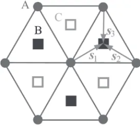
However, as we know, there are three variants of the Burgers vector to achieve the same stacking order for each fcc structural units, as the shear directions S1, S2 and S3 in
Fig. 3. Thus there are three possible combinations for two neighboring structural units. In the next section, the interaction between the structural units with different shear directions will be considered.
3.2 R type LPSO structure
For the R type LPSO, such as 18R in Fig. 1, one of the possible shear processes transforming 2H to 18R structure is that the shear directions for the three structural units are the same, i.e. ½1100=3. However, there are other two possible combinations of shear directions. These two combinations together with the one with same shear directions are shown in
Fig. 2 Schematic diagram of the system containing two arbitrary shaped inclusions+. The smallest cubic is so called cuboidal elements.
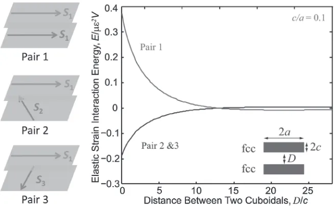
[image:2.595.104.233.69.193.2] [image:2.595.358.495.71.197.2]left side of Fig. 4, and are denoted as Pairs 1, 2 and 3. The elastic strain interaction energy between two structural units with different interspacing D is shown in the right side of Fig. 4. According to the interaction energy, the extreme (minimum/maximum) interaction is reached when two plates are attached to face to face, however only Pair 2 and 3 have negative interaction energy. These two combinations have the same interaction energy, because they are equivalent to each other in the crystallographic sense. Therefore, the combina-tion of shear direccombina-tions in Pair 2 and 3 is preferred. Starting from the two structural units’ configuration, one can construct the possible stacking structure for R type LPSO structure. Take Pair 2 for example, the shear direction in the third structural units under the one withS2should be S3in
order to minimize the elastic strain energy, because eitherS1
orS2will cause larger interaction energy. In the lowest elastic
energy configuration, three types of partial dislocation are operated successively in the nearest structural units. Any intermediated case will cause the increment of the interaction
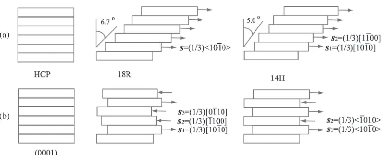
energy. Both of the highest and lowest elastic energy configurations are shown in the middle of Fig. 6(a) and 6(b) respectively. In the highest elastic energy configuration, the structural unit has the same shear direction, thus the total shear strain is large. However, in the lowest elastic energy configuration, three types of partial dislocation as shown in the figure are operated successively so that overall trans-formation strain is minimized for the R type LPSO and thus the system has the lowest elastic energy.
3.3 H type LPSO structure
For the H type LPSO, such as 14H in Fig. 1, one of the possible shear processes transforming 2H to 18R structure is that the shear directions for the two structural units are the opposite, e.g. ½1100=3 and ½1100=3. Similar to R type LPSO structure, for H type LPSO structure, there are also three possible combinations for the neighboring shear direction, and are denoted as Pair 13 shown in left side of Fig. 5. The elastic strain interaction energy between two
Fig. 4 Variation of the elastic strain energy with the spacing between two cuboidal shaped precipitate for different variants with®=®*. The energy is scaled by®¾2VwhereVis the volume of single unit, and¾is the shear strain. The combination of the shear directions are shown in the leftfigure.
[image:3.595.135.462.69.271.2] [image:3.595.130.464.321.522.2]structural units with different interspacing Dalongcaxis is shown in the right side of Fig. 5. According to the interaction energy, the extreme (minimum/maximum) interaction is also reached when two plates are attached to face to face, however only Pair 1 has negative interaction energy. Therefore, the combination of shear directions in Pair 1 is preferred. The minimum (negative) interaction energy in this case is twice lower than Pair 1 shown in Fig. 5 for R type structure, and it indicates that the H type other than R type LPSO may be preferred in the precipitation in terms of minimum elastic energy since the elasticfield due to the transformation strain (eigenstrain) is nearly cancelled. This result is consistent with the result that 14H is dominant after prolonged aging in Mg-Zn-Y alloy.4)Starting from the two units, one can construct
the possible stacking structure for the LPSO containing multiple structural units, and the opposite shear directions are operated in nearest structural units. Both of the highest and lowest elastic energy configurations are shown in the right of Fig. 6(a) and 6(b) respectively. In the lowest elastic energy configuration, overall transformation strain again is mini-mized like R type LPSO structure. In both R type and H type LPSO structure the overall elastic strain energy is minimized (negative interaction energy) when the summation of the Burgers vector of the partial dislocation is 0. Take 14H in Fig. 6 for example, the shear directions are ½1100=3 and ½1100=3, and their summation is 0. This point is consistent with the minimization of the overall transformation strain. The same situation may also happen in Al-Ag alloy with transformation from fcc to hcp structure.18,19)
4. Discussion
The possible stacking structure of H and R type LPSO structure has been proposed based on the criterion of minimizing the interaction energy. However, there are two questions have not been resolved, one is the LPSO structure is commonly synchronized with rare earth elements, and it must change the elastic constant of the fcc structural units, then the effect of the chemical ordering should be considered, the other question is about the spacing between two neighboring structural units, so far it was found that structural units are preferred to be closest to each other for the homogeneous case. Since the interaction energy between two
plates is depend on the elastic constant, plate morphology and distribution, transformation strain (eigenstrain) etc.,20)the effect of these factors will be discussed below.
4.1 Effect of modulus
The effect of the chemical ordering in LPSO structure is modeled by changing the elastic modulus of the precipitates. Figure 7 shows the elastic interaction energy between two structural units varies with the aspect ratio. The tendency is much similar in these cases. The harder is the inclusion, and the larger is the total elastic energy. The maximum interaction due to the interaction could be as large as 80%of the 2Esingle
when the aspect ratio approaches zero. The softer is the inclusion, the interaction energy percentage is slight larger. Figure 8 shows the elastic interaction energy varies with the central distance. Again, the tendency is similar for three cases. Therefore, one can conclude that the elastic constant would not change the results deduced in section 3. However, the preferred spacing between neighbor structure units with the minimum interaction energy is still unchanged, i.e. two units with lowest interaction energy are closely attached. Hence, other factors should be considered.
4.2 Effect of the dilatational strain
As mentioned before, the formation of the structural unit in LPSO structure is synchronized with the chemical
Fig. 7 Variation of the elastic strain interaction energy with different aspect ratio between two cuboidal shaped precipitates.
(a)
(b)
[image:4.595.105.493.65.223.2] [image:4.595.311.542.278.433.2]order/enrichment.46) The chemical enrichment may cause a noticeable negative dilatational strain along the [0001] direction according to the experimental analysis.21,22) There-fore, both of the shear component induced by structural transformation and the dilatational component due to the chemical enrichment are taken into accounted.
In the other extreme case, if the shear strain is absent and the dilatational strains in the three axes of the inclusion are same, this case could be possible when composition modulation occurs before the structure transformation. The calculated interaction elastic energy is shown in Fig. 9(a), the minimum interaction energy could be reached when two structural units separate by about 0.2c. When the aspect ratio
spacing, the spacing approaches zero. When the shear strain is taken into account, i.e. both shear and dilatational strain coexist, the situation is changed. As shown in the Fig. 9(b), the negative dilatation strain ¤ changes from ¹0.1£ to ¹£ where £ is the shear component, the minimum of elastic energy with the spacing between the units is reached at zero. It means the maximum interaction energy occurs when two structural units are attached to each other. Various dilatational strain components do not change the continuous decreasing tendency of the interaction energy. Figure 9(c) shows the effect of the aspect ratio. More negative interaction energy occurs when the aspect ratio is smaller. Figure 9(d) shows the case stimulated from the experimental observation. In the case the alloy enrichment occurs before another structural unit forms in neighbor, thus one structural unit with only dilatational strain and the other with shear strain are considered in this calculation. However, interaction energy is positive in this case and it seems such a configuration is energetically unfavorable. Therefore, there are should be another kind force attractive or repulsive between two neighboring structure units, such as the chemical effect in the development of stacking of structural units in LPSO structure.23) The phase field simulation carried out by Koyama and Tsukada24)may shed some light on this point.
4.3 Nucleation site
In above considerations, the structure units are assumed to be of the same size. Since the stressfield around the structure unit varies with the location, thus there would be some location preferred for nucleation, i.e. the interaction energy between two different size structure units is negative.
Fig. 8 Variation of the elastic strain interaction energy with different inter distance between two cuboidal shaped structural units with aspect ratio
c/a=0.1.
(a) (b)
(c) (d)
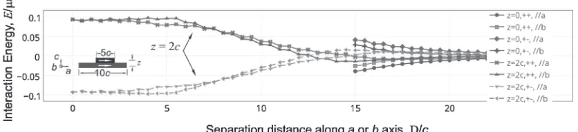
[image:5.595.54.282.68.234.2] [image:5.595.129.468.475.749.2]Figure 10 shows the calculation results in the condition that the structure units with two different size a=10cand
a=5c, the shear directions of the two units are same (+ +) or opposite (+¹), and the units separation are set in the same layer (z=0) or stacking along c direction (z=2c) where the geometry is defined in the innerfigure of Fig. 10. According to Fig. 10, the preferred nucleation site for the structure unit with opposite shear directions is at the top of existing structure unit, while that for same shear directions is at the edge of the exist structure unit in the same layer. The minimum interaction energy is achieved when two units are closely attached.
5. Conclusions
The elastic interaction between the structural units in LPSO structure is investigated. It is shown that the interaction energy between the structural units is significant for pure shear if the aspect ratio is small, and the interaction energy could vary from positive value to negative value when the shear direction for the structural units varies. Since there are three variants of shear directions to achieve the same stacking order for each fcc structural units, various combinations of the shear directions are considered for both R type and H type LPSO structure. The lowest elastic energy configuration is obtained. The possible low energy config-urations associated for the LPSO structures are (1) for H type structure, the opposite shear directions (or Burgers vectors of the partial dislocations) are operated in nearest structural units; (2) for R type structure, all three types of partial dislocation are operated successively in the nearest structural units.
Furthermore, according to the elastic energy study, the preferred nucleation site for the structure unit with opposite shear directions is at the top of existing structure unit, while that for same shear directions is at the edge of the exist structure unit in the same layer.
The effect of the elastic constant and dilatational strain due to the chemical ordering/enrichment during the formation of the structural units is considered. Both factors do not change the conclusion above when the aspect ratio is small. Therefore, the spacing between the structural units in LPSO structure cannot be rationalized only in elastic strain energy consideration.
Acknowledgement
This work was supported by MEXT KAKENHI Grant Number 23109006 (Grant-in-Aid for Scientific Research on Innovative Areas, “Synchronized Long-Period Stacking Ordered Structure³The Evolution of the Material Science for Innovative Development of the Next-generation Light-weight Structure Materials³”).
REFERENCES
1) Y. Kawamura and M. Yamasaki:Mater. Trans.48(2007) 29862992.
2) K. Hagihara, A. Kinoshita, Y. Sugino, M. Yamasaki, Y. Kawamura, H. Y. Yasuda and Y. Umakoshi:Acta Mater.58(2010) 62826293.
3) K. Hagihara, A. Kinoshita, Y. Fukusumi, M. Yamasaki and Y. Kawamura:Mater. Sci. Eng. A560(2013) 7179.
4) Y. M. Zhu, A. J. Morton and J. F. Nie:Acta Mater.58(2010) 2936 2947.
5) E. Abe, Y. Kawamura, K. Hayashi and A. Inoue:Acta Mater.50(2002) 38453857.
6) E. Abe, A. Ono, T. Itoi, M. Yamasaki and Y. Kawamura:Philos. Mag. Lett.91(2011) 690696.
7) D. Egusa and E. Abe:Acta Mater.60(2012) 166178.
8) Y. M. Zhu, A. J. Morton and J.-F. Nie:Acta Mater.60(2012) 6562 6572.
9) J. W. Christian:Metall. Mater. Trans. A25(1994) 18211839.
10) T. Furuhara and X. F. Gu:Mater. Trans.54(2013) 675679.
11) K. Zhou, L. M. Keer and Q. J. Wang:Int. J. Numer. Meth. Eng.87
(2011) 617638.
12) Q. Li and P. Anderson:J. Elasticity64(2001) 237245.
13) T. Mura:Micromechanics of Defects in Solids, (Martinus Nijhoff Pub., 1987).
14) S. Liu, Q. Wang and G. Liu:Wear243(2000) 101111.
15) J. D. Eshelby:Proc. R. Soc. London A241(1957) 376396.
16) L. J. Slutsky and C. W. Garland:Phys. Rev.107(1957) 972976.
17) Z. Yang, M. F. Chisholm, G. Duscher, X. Ma and S. J. Pennycook:Acta Mater.61(2013) 350359.
18) J. M. Howe, H. I. Aaronson and R. Gronsky:Acta Metall.33(1985) 649658.
19) T. Furuhara and T. Maki:Materia Japan36(1997) 483490.
20) W. C. Johnson and P. W. Voorhees:J. Appl. Phys.61(1987) 1610 1619.
21) T. Kiguchi, Y. Ninomiya, K. Shimmi, K. Sato and T. J. Konno:Mater. Trans.54(2013) 668674.
22) J. F. Nie, K. Oh-ishi, X. Gao and K. Hono:Acta Mater.56(2008) 60616076.
23) S. Iikubo, K. Matsuda and H. Ohtani:Phys. Rev. B86(2012) 054105.
[image:6.595.90.508.77.173.2]24) T. Koyama and Y. Tsukada: Phasefield modeling of mictostructure formation of LPSO in Mg alloy, Project report of Synchronized Long-Period Stacking Ordered Structure, Biwako, (2013).