Nano-Sized Indium Oxide Powder Synthesized by Spray Pyrolysis Process
Jaekeun Yu
1, Seonggu Kang
2, Jinbae Kim
2, Jwayeon Kim
1, Joungsu Han
3,
Jaewoon Yoo
1, Sangwoon Lee
1and Zousam Ahn
41
Department of Advanced Materials Engineering, Hoseo University, Asan 336-795, Korea
2Department of Chemical Engineering, Hoseo University, Asan 336-795, Korea 3Technology Innovation Center, Hoseo University, Asan 336-795, Korea 4Agency for Technology and Standards, Gwacheon 427-716, Korea
In this study, nano-sized indium oxide powder with average particle size below 50 nm is synthesized from indium chloride solution by a spray pyrolysis process. This study also examines influences of reaction factors on the properties of the synthesized powder. These factors include the reaction temperature, the inflow speed of the raw material solution and the inflow speed of the environmental air.
As the reaction temperature increases from 850 to 1000C, the average particle size of the generated powder increases from around 30 nm
to 100 nm, the microstructure gradually becomes solid, the XRD peak intensity gradually increases and the specific surface area decreases. As the inflow speed of the raw material solution increases from 2 to 5 mL/min, the average particle size of the powder decreases. When the inflow speed is 10 mL/min, the average particle size is larger than that at 5 mL/min. When the inflow speed of solution is 50 mL/min, the average particle size is smaller and the microstructure of the powder is less solid than that at 10 mL/min. The variations of the XRD peak intensity and the specific surface area show the similar tendency to that of the average particle size.
As the air pressure increases from 0.1 to 0.5 kg/cm2, the average particle size of the powder shows a not significant change from 90 nm to 100 nm. As the air pressure increases up to 1 kg/cm2and 3 kg/cm2, the average particle size decreases down to 50 nm and the XRD peak intensity decreases. [doi:10.2320/matertrans.47.1838]
(Received March 27, 2006; Accepted May 17, 2006; Published July 15, 2006)
Keywords: nano-sized, indium oxide powder, indium chloride solution, spray pyrolysis process, average particle size, reaction factors
1. Introduction
Spray pyrolysis reaction is one of the methods of manufacturing nano-sized metal oxide powder. In this reaction, chemical components are uniformly blended in the solution state so as to make a complex solution, which is in turn sprayed into a reaction furnace with a high temper-ature. In the furnace, spray pyrolysis reaction Is accom-plished instantly, and as a result, the ultra-fine metal oxide powder is formed. The advantages of this method include the following: 1) processes such as the mixing, calcination, and milling of solid powder can be omitted, which therefore makes the whole process relatively simple; 2) mixing with impurities can be reduced, and the properties of the generated particles can be controlled according to the different conditions of the pyrolysis reaction. Presently, several manufactories, such as Scimarec of Japan, Merck of German, and SSC of USA, are producing highly functional ceramic powders manufactured using the spray pyrolysis method. Meanwhile, research activities related to the spray pyrolysis
method are being conducted by Majumdar,1) Pluym,2,3)
Kodas,4)Elmasry,5)Zhang6) and Liu,7)and the applications
of this method are expanding quickly. For examples, in steelmakings, this method is used to manufacture iron oxide powder from the waste acid solution generated in the process of rinsing the surface of hot rolled steel sheets with hydrochloric acid solution. Also, CuO powder with the average particle size below 1 um is manufactured from waste copper chloride solution, and Ni-ferrite powder with the average particle size below 100 nm is manufactured from the waste solution generated in the shadow mask manufacturing
process.8)However, except for the aforementioned examples,
spray pyrolysis method hasn’t been applied for the manu-factures of single substance oxide powder and compound
oxide powder in other industrial fields. Domestically, in particular, spray pyrolysis method has not been applied for the manufacture of ITO powder and indium oxide powder, while their applications in video display products are expanding rapidly, and most of these powders have to be imported from Japan and other countries. Thermal
decom-position method,9)emulsion technique10)and
hydrothermal-calcination process11)have been attempted for the
manufac-ture of nano-sized In2O3 powder. The nano particles
generated by theses processes exhibit high purity and uniform particle size. However, these processes are restricted in terms of the compositions limits of the raw material solutions and not suitable for mass production. Spray pyrolysis process is not only suitable for mass production, but also enables a wide-spectrum of solution compositions. Since this paper is a preliminary study on waste ITO recycling technology, the selection of spray pyrolysis process is therefore considered as a wise decision.
In this study, a chloride solution that contains indium component is used as the raw material of the spray pyrolysis process to generate an indium oxide powder with an uniform particle size distribution and structure, and an average particle size below 100 nm. This study is also intended for determining the effects of the reaction factors, such as reaction temperature, inflow speeds of raw material solution and surrounding atmosphere, on the properties of the generated powder.
2. Experimental
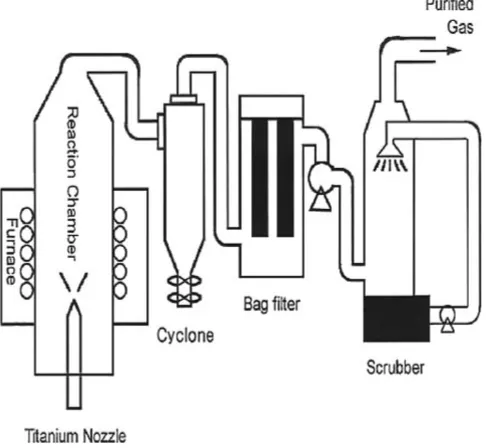
pyrolysis process. The indium dissolved in HCl solution was the indium chip with purity of 99.9%, and the generated solution was almost saturated. In order to generate an ultra fine solid powder with an uniform particle size distribution and shape, an efficient spray pyrolysis system was specially designed and built for this study. This system enables the following: the raw material solution can be sprayed into the reaction furnace after being efficiently micronized, the pyrolysis reaction can be completed perfectly because of the uniform heat distribution inside the reaction furnace, the generated powder can be collected effectively by a powder collection device named bag filter, and the toxic gases generated in the process can also be cleansed by a scrubber. The schematic diagram of this system is shown in Fig. 1. A titanium-made nozzle with the inside diameter of 2 mm was used as the micronization device for this system. To ensure the uniform temperature distribution inside the reaction furnace, 4 furnaces were combined together to make a 150 cm-high 4-zone type cylindrical tube furnace, and the maximum temperature inside this furnace can reach
1500C. There were 6 bags in the powder collection device
with an inside volume of 500 liters. The generated HCl gas passing through the bag filter was then treated by a scrubber with a dual-fluid nozzle. As a result, the HCl gas was dissolved and collected in the form of HCl solution.
In the experiment, the raw material solution was fed through one inlet of the nozzle with inflow speeds of 2– 50 mL/min., and the pressurized air with a pressure of 0.1–
3 kg/cm2, was fed through the other inlet of the nozzle so that
the raw material solution can be micron zed. The micronized solution then underwent pyrolysis reaction in the furnace
with an internal temperatures of 850–1000C. Given various
conditions of reaction, nano-sized indium oxide powder with diverse physical and chemical properties was generated. In addition, SEM (variations of particle size distribution, average particle size and shape) and XRD (variations of powder phase and structure) analysis, and the measurements of specific surface area were also performed.
droplets. And InCl3 in solid phase undergoes the pyrolysis
reaction (2InCl3þ3H2O¼In2O3þ6HCl), and In2O3
par-ticles are formed. The solvent inside the droplets cannot get through the solidified surface layer easily. As a result, the interior pressure inside the droplets continuously increases, which eventually leads to the burst of the droplets and the generation of nano particles. When the reaction temperature
is at 850C, as soon as the micronized droplets flow into the
reaction zone, the solvent near to the droplet surface is more rapidly vaporized, which causes the droplets to burst severely. Because of the extremely narrow reaction zone,
and because the reaction temperature of 850C cannot ensure
the sufficient sintering of the fine solid powder, the generated powder appears with an average particle size below 30 nm, and the ultra fine particles shows a strong tendency of mutual cohesion. This result is conformed by TEM analysis of
Fig. 3. When the reaction temperature increases up to 900C,
because of the more rapid evaporation of the solvent along with the temperature rise, the burst of droplets at the initial stage of the spray pyrolysis process appears severer. Thus, the average particle size of the generated powder appears smaller and the particle size distribution becomes more
ununiform than the situation at 850C. Although the sintering
of the ultra fine particles is proceeded, the average particle size of the generated powder appears similar to that of the
powder generated at 850C, because the reaction temperature
of 900C still cannot ensure the sufficient sintering of the fine
solid powder. In order to conform the single crystal of individual particles, Fig. 3 also shows the selective diffrac-tion pattern of single particle. And selective diffracdiffrac-tion patterns of other particles were same with Fig. 3. With these results, we concluded that generated particles were composed of solid single crystal. When the reaction temperature
increases up to 950C, the burst of droplets at the initial
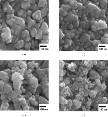
stage of the spray pyrolysis reaction appears severer. But because the sintering of particles is proceeded extremely fast due to the high reaction temperature, the particle size distribution appears so ununiform that the particle size shows a bimodal distribution with the particle size from 30 nm to the maximum of 100 nm. Meanwhile, the average particle size increases significantly, the particle surface appears extremely solid, most of the particles appear in the shape of polygon, and the mutual cohesion between particles is significantly lessened. When the reaction temperature increases up to
1000C, the evaporation of the solvent occurs instantly on the
[image:2.595.48.291.76.300.2]pressure inside the droplets increases significantly, and in turn the severe burst of the droplets occurs. At the initial stage of the reaction, the particle size of the generated powder appears extremely small. But because the sintering of particles is proceeded extremely fast due to the high reaction temperature, the particle size distribution appears so ununi-form that the particle size shows a bimodal distribution with the particle size ranging from 30 nm to the maximum of 150 nm. The average particle size of the generated powder, on the other hand, increases significantly in contrast to the
situation at 950C, the surface structure of the powder
becomes much more solid, and the generated powder appears in the form of independent particles.
Figure 4, the results of the XRD analysis, shows the Miller indexes of the peaks and phases of the generated powder under different reaction temperatures. It can be seen from this
figure that the only In2O3 phase is exist regardless of the
reaction temperature. When the reaction temperature is at the
lowest 850C, chlorides such as InCl
3does not appear. It can
be concluded that, the pyrolysis reaction (2InCl3þ3H2O¼
In2O3þ6HCl) is completely proceeded within the
temper-atures ranges of this study. As the reaction temperature
increases from 850 to 900C, the intensity of XRD peak
shows almost no variation. This result, consistent with what is shown in Fig. 2, is caused by the likeness of average particle sizes at two different reaction temperatures. As the
reaction temperature increases from 950 to 1000C, the
XRD peak intensity gradually increases. This result, also consistent with what is shown in Fig. 2, is caused by the increase of average particle size along with the temperature rise.
Figure 5 shows the specific surface area of the generated powder relative to the reaction temperature. As the reaction
temperature increases from 850 to 900C, there is almost
no change with the specific surface area. This result, con-sistent with what is shown in Fig. 2, is caused by the likeness of the average particle sizes at two different reaction temperatures. As the reaction temperature increases from
950 to 1000C, on the other hand, the specific surface area of
the particles significantly decreases. The specific surface area
at 1000C is only the half of that at 850 or 900C. This result
is owing to the fact that the average particle size of the powder increases, and that the structure of it becomes much more solid.
(b) (a)
(c) (d)
[image:3.595.110.484.74.467.2]3.2 Powder properties affected by inflow speed of raw material solution
Figure 6 shows the microstructure changes of the gener-ated powder (revealed by SEM analysis) relative to the inflow speed of the raw material solution into the reaction furnace,
given the reaction temperature is 900C and the air pressure
is 3 kg/cm2. When the inflow speed of the raw material
solution is at the lowest of 2 mL/min, large particles with the size of 100 nm and small particles with the size of 20 nm coexist. Despite the uneven particle size distribution, the structure of the generated powder appears comparatively solid. Generally, the average size of the liquid droplet formed through a dual-fluid nozzle can be calculated according to
formula (1).12)
X¼585
ffiffiffi
p
pffiffiffiþ579
pffiffiffiffiffiffi
0:45 1000Ql
Qa
1:5
ð1Þ
Where X is the average size of the liquid droplet, Qlis the
amount of the solution,Qais the amount of air, ands,and
are, respectably, the surface tension, spraying speed and viscosity of the solution.
(a)
(b)
Fig. 3 TEM photographs of produced powder and selective diffraction pattern of single particle at reaction temperature of 900C, 5 mL/min. inlet
speed of solution and 3 kg/cm2 air pressure. (a) TEM photographs of produced powder. (b) Selective diffraction pattern of single particle.
Fig. 4 XRD patterns of powder according to reaction temperature at 5 mL/ min. inlet speed of solution and 3 kg/cm2air pressure. (a) 850C (b) 900C
(c) 950C (d) 1000C.
850 900 950 1000 4
6 8 10 12
BET ( m
2
/
g )
Temperature (
°
C
)
[image:4.595.74.263.73.509.2] [image:4.595.318.539.409.688.2]When the inflow speed of solution is very slow (2 mL/ min), there is almost no burst of droplets during the pyrolysis process due to the small size of the micronized liquid droplets. Thus, the average particle size of the generated powder is expected to be extremely small. Nevertheless, when there is a large amount of micronized small-size droplets, the cohesion between droplets becomes increas-ingly severe. In formula (2), assuming that Brown movement
is the cause of the collisions between droplets, and thatis a
constant, the possibility of cohesion between the prelimi-narily micronized droplets increases considerably along with the decrease of droplet size.
ðNt=NtÞ ¼1=ð1þt=tcÞ ð2Þ
Where No is the amount of preliminarily micronized
droplets, Nt is the amount of droplets at the time oft,Tcis
2=andis the cohesion speed constant.
Therefore, before the start of pyrolysis reaction, small-size droplets resulting from the slow inflow speed of the solution and enlarged droplets resulting from the cohesion between droplets are expected to coexist. For the eventually generated powder, particles with the size ranging from 20 to 100 nm
shall coexist. When the inflow speed is 5 mL/min, the average particle size of the generated powder is around 30 nm, and the particle size distribution appears compara-tively uniform. The droplet size at the inflow speed of 5 mL/ min increases significantly in contrast to the situation with the inflow speed of 2 mL/min, the cohesion between droplets is lessened considerably, and there is no significant burst of droplets during the pyrolysis process because of the com-paratively small size of the micronized droplets. When the inflow speed is 10 mL/min, particles with the sizes ranging from 30 to 60 nm coexist, and the particle size distribution is extremely ununiform. This result is caused by the complex effects of the following processes: 1) As the inflow speed increases up to 10 mL/min, the droplet size increases, and the particle size of the generated powder increases resultingly; and 2) Along with the increase of the droplet size, the burst of the droplets becomes increasingly severe. As the inflow speed of the solution increases to 50 mL/min, the average particle size is around 40 nm. The generated powder shows a non-solid structure and the intense cohesion between par-ticles. This phenomenon results from the complex effects of the following processes: 1) As the inflow speed increases up
(a) (b)
(c) (d)
Fig. 6 SEM photographs of produced powder according to inlet speed of solution at reaction temperature of 900C, raw material solution
[image:5.595.115.488.75.473.2]to 50 mL/min, the size of the micronized droplets increases significantly, and the burst of the droplets becomes increas-ingly severe; and 2) Along with the increase of the evaporation heat of the solvent inside the droplets, the sintering between particles diminishes significantly.
Figure 7 shows the phase change of the generated powder by XRD analysis relative to the inflow speed of the raw material solution given the same reaction conditions as those adopted in Fig. 6. It is shown from Fig. 7 that, regardless of the inflow speed, the only existing form of the generated
powder is In2O3. As the inflow speed increases from 2 to
5 mL/min, the XRD peak intensity diminishes significantly. The reason of this phenomenon, which is consistent with the results shown in Fig. 6 is believed to be: when the inflow speed is 2 mL/min, because of the significant cohesion between the extremely small droplets micronized by the nozzle, the average particle size of the generated powder is larger than the situation with the inflow speed of 5 mL/min. When the inflow speed increases up to 10 mL/min, the XRD peak intensity increases significantly in contrast to the situation with the inflow speed of 5 mL/min, and is similar to the situation with the inflow speed of 2 mL/min. This result is almost consistent with the variation tendency of the average particle size of the generated powder. When the inflow speed increases up to 50 mL/min, the XRD peak intensity diminishes significantly in contrast to the situation with the inflow speed of 10 mL/min. When the inflow speed is 50 mL/min, the burst of the micronized droplets becomes extremely severe and the sintering between particles dimin-ishes as the evaporation heat of the solvent inside the droplets increases. Thus, the average particle size decreases signifi-cantly, and the generated powder shows a non-solid structure.
Figure 8 shows the variation of specific surface area of the powder relative to the inflow speed of the solution given the same reaction conditions as those adopted in Fig. 6. As the inflow speed increases from 2 to 5 mL/min, the specific surface area of the powder shows an increasing tendency. It is considered that this result is mainly caused by the increase of the average particle size of the powder as the inflow speed increases. As shown in Fig. 6, when the inflow speed increases up to 10 mL/min, the average particle size is larger than the situation with the inflow speed of 5 mL/min, thus the specific surface area decreases again to the level similar to the situation with the inflow speed of 2 mL/min. When the inflow speed increases up to 50 mL/min, the average particle size of the generated powder decreases, and the specific surface area increases significantly.
3.3 Powder properties affected by air pressure
Figure 9 shows the microstructure changes of the gener-ated powder (revealed by SEM analysis) relative to the pressure of the environmental air that flows into the reaction
furnace, given a reaction temperature of 900C and an inflow
speed of 10 mL/min. Along with the increase of the air pressure, the average particle size of the powder shows a tendency of gradual decreasing, and the particle size distribution collectively appears ununiform. When the air
pressure is 0.1 kg/cm2, because of the large size of the
micronized droplets and the high concentration of the solution, severe burst of the droplets occurs during the pyrolysis process, and the particle size distribution appears extremely ununiform. However, due to the significant increase of the micronized droplet size, the generated powder shows an extremely large average particle size of 90–100 nm. Fig. 7 XRD patterns of powder according to inlet speed of solution at
reaction temperature of 900C and 3 kg/cm2air pressure. (a) 2 mL/min. (b) 5 mL/min. (c) 10 mL/min. (d) 50 mL/min.
8 10
2 5 10 50
Inlet speed of solution (cc/min)
[image:6.595.54.285.70.329.2] [image:6.595.318.540.74.354.2]When the air pressure increases up to 0.5 kg/cm2, due to the
decrease of droplet size and the diminished burst of droplets, the particle size distribution appears comparatively uniform. Thus, compared with the situation with the air pressure of
0.1 kg/cm2, the large-size particle appears comparatively
small, but there is no significant change of average particle
size. When the air pressure increases up to 1 kg/cm2, due to
the decrease of droplet size and the diminished burst of droplets, the particle size distribution appears more uniform. Along with the increase of air pressure, the decreasing effect on droplet size plays a dominant role, and the average particle size decreases below 60 nm. The loose structure of the powder results from the complex effects of the following processes: 1) The evaporation of solvent inside the droplets becomes easy along with the decrease of droplet size; and 2) the ambient temperature in the furnace decreases along with the increase of air pressure. When the air pressure increases
up to 3 kg/cm2, the droplet size significantly decreases, and
the average particle size of the powder decreases more. Along with the increase of air pressure, the ambient temper-ature in the furnace decreases more. Because of this effect, the sintering between particles diminishes, the particle size
distribution becomes ununiform, and the structure of the powder appears loose.
Figure 10 shows the property change of the generated powder (revealed by XRD analysis) relative to the pressure of the environmental air that flows into the reaction furnace given the same reaction conditions as those adopted in Fig. 9. It is shown from Fig. 10 that, regardless of the air pressure change, the only existing form of the generated powder is
In2O3. Along with the increase of air pressure, the XRD peak
intensity gradually increases. Especially when the air
pressure is above 0.5 kg/cm2, there is a significant increase
of the XRD peak intensity. As shown in Fig. 9, when the air
pressure is at the lowest of 0.1 kg/cm2, because of the large
size and the severe burst of the droplets, the particle size distribution of the generated powder appears extremely
ununiform. When the air pressure increases up to 0.5 kg/cm2,
the particle size distribution of the generated powder appears comparatively uniform, but there is no evident change with the average particle size of the powder. Hence, even though
the air pressure increases from 0.1 to 0.5 kg/cm2, there is
no evident change with the XRD peak intensity. When the
air pressure increases from 1 to 3 kg/cm2, because the
(a) (b)
(c) (d)
Fig. 9 SEM photographs of produced powder according to air pressure at reaction temperature of 900C, raw material solution of 350 g/‘
[image:7.595.115.482.75.471.2]average particle size of the generated powder continuously decreases, the XRD peak intensity also decreases.
Figure 11 shows the specific surface area of the generated powder relative to the inflow speed of the environmental air.
Until the air pressure increases to 0.5 kg/cm2, there is no
significant change with the specific surface area of the generated powder. The reason for this result, which is consistent with Fig. 9, is believe to be that, there is no evident change with the average particle size along with the increase
of air pressure. When the air pressure is 1 kg/cm2, there is a
remarkable decrease of droplet size and the average particle
size decreases. When the air pressure is 3 kg/cm2, along with
the increase of air pressure and the burst of droplets, the droplet size significantly decreases, the average particle size decreases more, and the specific surface area increases significantly.
4. Conclusions
In this study, nano-sized indium oxide powder with the average particle size below 50 nm is generated from the raw material solution containing indium element by the spray pyrolysis reaction. This study also investigates the effects of the reaction factors, such as the reaction temperature, the inflow speed of the raw material solution and the inflow speed of the environmental air on the properties of the generated powder.
(1) As the reaction temperature increases from 850 to
1000C, the average particlesize of the generated
powder increases from around 30 to 100 nm, the
microstructure gradually becomes more solid, though the particle size distribution becomes increasingly ununiform. Along with the increase of reaction temper-ature, the XRD peak intensity gradually increases and the specific surface area decreases. Especially when the
reaction temperature is 1000C, the specific surface
area decreases by 1/3 in contrast to the situations in
which the reaction temperatures are 850 and 900C.
(2) As the inflow speed of the raw material solution increases from 2 to 5 mL/min, the average particle size of powder decreases, the particle size distribution becomes more uniform, the XRD peak intensity decreases and the specific surface area increases. When the inflow speed is 10 mL/min, in contrast to the situation with the inflow speed of 5 mL/min, the average particle size increases, the particle size distri-bution is more ununiform, the XRD peak intensity increases and the specific surface area decreases. When the inflow speed of the solution increases to 50 mL/ min, the average particle size is around 30–40 nm, the particle size distribution is comparatively uniform, the microstructure of the powder is less solid, the XRD peak intensity decreases and the specific surface area of the powder increases.
(3) As the air pressure increases from 0.1 to 0.5 kg/cm2, the
average particle size shows a not evident change from 90 to 100 nm, and there are no evident changes with the XRD peak intensity and the specific surface area. As the
air pressure increases up to 1 and 3 kg/cm2, the average
[image:8.595.55.284.70.354.2]particle size decreases down to 50 nm, the XRD peak intensity decreases and the specific surface area increases.
Fig. 10 XRD patterns of produced powder according to air pressure at reaction temperature of 900C and 10 mL/min. inlet speed of solution.
(a) 0.1 kg/cm2(b) 0.5 kg/cm2(c) 1 kg/cm2(d) 3 kg/cm2.
Air pressure (kg/cm
2)
2
0.5
[image:8.595.313.540.71.349.2]0.1 1 3
Acknowledgements
This work was supported by the Regional Innovation Center of Hoseo University in Korea.
REFERENCES
1) D. Majumdar, T. A. Shefelbine and T. T. Kodas: J. Mater. Res.11
(1996) 2861–2868.
2) T. C. Pluym, S. W. Lyons, Q. H. Powell, A. S. Gurav and T. T. Kodas: Mat. Res. Bull.28(1993) 369–376.
3) T. C. Pluym and T. T. Kodas: J. Mater. Res.10(1995) 1661. 4) T. Kodas and A. Datye: J. Appl. Phys.65(1989) 2149–2151.
5) M. A. A. Elmasry, A. Gaber and E. M. H. Khater: Powder Technology
90(1997) 165–168.
6) S. C. Zhang and G. L. Messing: J. Am. Ceram. Soc.73(1990) 61–67. 7) T. Q. Liu, O. Sakurai, N. Mizutani and M. Kato: Mat. Res. Bull.21
(1986) 3698–3702.
8) J. K. Yu, G. H. Kim, T. S. Kim and J. Y. Kim: Mater. Trans.46(2005) 1695–1700.
9) H. Zhou, W. Cai and L. Zhang: Mater. Res. Bull.34(1999) 845–849. 10) P. S. Devi, M. Chatterjee and D. Ganguli: Mater. Lett.55(2002) 205–
210.
11) C. P. Udawatte and K. Yanagisawa: J. Am. Ceram. Soc.84(2001) 251– 253.
12) J. K. Yu, S. K. Suh, S. G. Kang, J. Y. Kim, S. H. Park, Y. S. Kim, J. H. Choi and J. G. Sohn: J. of Korean Inst. of Resources Recycling12