Processing and Characterization of a New Composite Metal Foam
Afsaneh Rabiei, Lakshmi Vendra
*1, Nick Reese
*2, Noah Young
*2and Brian P. Neville
*1Department of Mechanical and Aerospace Engineering, North Carolina State University, Raleigh, NC 27695-7910, USA
New closed cell composite metal foam has been processed using both casting and powder metallurgy (PM) techniques. The foam is comprised of steel hollow spheres packed into a dense arrangement, with the interstitial spaces between spheres occupied with a solid metal matrix. Using the casting technique, an aluminum alloy infiltrates the interstitial spaces between steel spheres. In the PM technique, steel spheres and steel powder are sintered to form a solid, closed cell structure. The measured densities of the Al-Fe composite foam, low carbon steel foam, and stainless steel foam are 2.4, 2.6, and 2.9 g/cm3with relative densities of 42, 34, and 37%, respectively.
The composite metal foams composite materials developed in this study displayed superior compressive strength as compared to any other foam being produced with similar materials. The compressive strength of the cast Al-Fe foam averaged 67 MPa over a region of 10 to 50% strain, while the low carbon steel PM foam averaged 76 MPa over the same strain region, and the stainless steel PM foam averaged 136 MPa over the same region. Densification began at approximately 50% for the cast foam and ranged from 50 to 55% for the PM foams. The strength to density ratio of the product of both techniques exceeded twice that of foams processed using other techniques with similar materials.
[doi:10.2320/matertrans.47.2148]
(Received February 28, 2006; Accepted April 24, 2006; Published September 15, 2006)
Keywords: metal foam, energy absorption, hollow spheres, compression strength, plateau stress
1. Introduction
Metal foams are materials which display a unique combination of physical and mechanical properties. Their light weight, high specific stiffness, high strength to weight ratios, and greatly increased energy absorbing capabilities make them ideal candidates for use in the automotive and aerospace industries.1)They have been shown to experience fatigue degradation in both tension and compression.2,3)
Under compression, localized failure begins preferentially at larger cells within the assembly, which eventually leads to the formation of collapse bands.2,3)
The performance of existing foams has not been promising due to strong variations in their cell structure.2–4) Most
commercially available cellular metals do not achieve the properties predicted from the scaling relations that connect the mechanical behavior of the foam to the bulk material they are produced from.5–7) This can be partially attributed to
morphological defects in the structure such as missing cell walls, wiggles in the cell wall, etc.7) To gain the full advantages of these lightweight materials, these defects must be eliminated.8)
One technique that has been previously explored is to use preformed hollow spheres to form the cells of the material. Two such hollow sphere materials have been created and studied by Georgia Tech and Fraunhofer.9–11)These materials
exhibited plateau stresses of 5 and 23 MPa respectively, with energy absorbing capabilities of 2 and 10 MJ/m3
respective-ly, up to 50% strain.
We have produced a new type of closed cell foams by filling the vacancies around a random dense collection of preformed hollow spheres with a solid matrix material, either through casting12,13)or through powder metallurgy (PM)12,14) with the aim of increasing their energy absorption and strength. The studies presented in this paper have shown that
by filling in the vacancies, a stronger material with a much greater energy absorbing capability can be produced. This has the effect of increasing the stability of the cell walls, reducing the likelihood of their buckling under loading. While doing this obviously increases the density of the material, the resulting strength to density ratios are higher than those reported in the literature for foams processed using similar materials and different techniques. The physical properties of these materials can be altered by changing the size and wall thickness of the hollow spheres. By using preformed hollow spheres of known dimensions, the proper-ties of the foam become more uniform and predictable.
These processes allow both similar and dissimilar matrix and hollow sphere materials to be used in manufacturing of composite metal foams. In the casting process, dissimilar materials must be used; specifically the matrix must be of a lower melting temperature material than that of the hollow spheres. In the PM process, similar materials can be used because the processing temperature is below the melting temperature of the components. Additionally, similar materi-als may lead to better bonding strength between the matrix and the sphere walls.
2. Materials, Processing and Characterization
2.1 Material and equipment
The hollow spheres used in these studies are produced by Fraunhofer in Dresden Germany, using a PM technique.9,11)
The composition of the low carbon (LC) steel spheres is <0:002% oxygen, <0:007% carbon, and the balance iron. Two sets of LC steel hollow spheres were produced with nominal outer diameters of 3.7 and 1.4 mm with wall thick-nesses of 200 and 50mm, respectively. The porosity of the sphere walls is approximately 5% for both sizes. The 316L stainless steel hollow spheres have a nominal outside diameter of 2 mm with a wall thickness of 100mm. The porosity of the sphere walls ranged from 6–15%.
The solid matrix in these studies is produced by two *1Graduate Student, North Carolina State University
*2Undergraduate Student, North Carolina State University
Special Issue on Porous and Foamed Metals —Fabrication, Characterization, Properties and Applications—
different methods. In the casting method, aluminum 356 casting alloy was used. In the PM method, low carbon Ancorsteel-1000C from ARC Metals was used for the LC steel composite foam. An additional 0.8% graphite was mixed in with the steel powder for strengthening15) and to
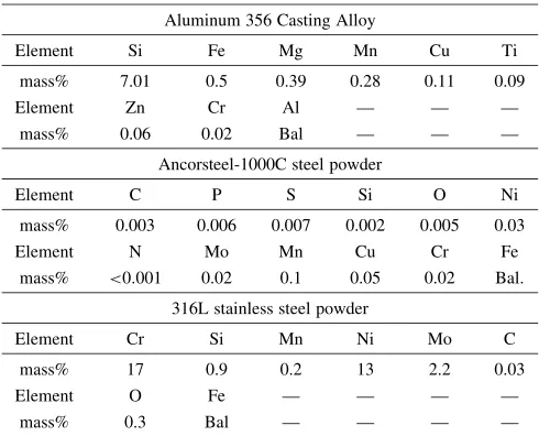
control shrinkage of the matrix during sintering.16) The powder used for the stainless steel foam is 316L stainless steel from ANCOR Specialties. No additions were made to the stainless steel powder. The compositions of the matrix materials are shown in Table 1.
The molds for producing these materials had to be large enough to maintain a minimum of 8–10 spheres per edge to eliminate any edge effects so as to produce a meaningful representation of a bulk material.2)Other considerations were
simplicity of manufacture, ease of assembly and ease of part removal. The mold for the casting method is a gravity fed design made of carbon steel, with a mold cavity of121mm
144mm54mm. The mold for the PM method was made from 304 stainless steel, with a mold cavity of 51mm
51mm89mm. Prior to processing, the surfaces of the molds are cleaned and then coated with a boron nitride mold release to prevent bonding between the sample and the mold and to facilitate removal from the mold. To avoid the build-up of oxides from inside the mold, non co-linear holes were drilled into the spacer and mold cap. This allows venting of the atmosphere and any outgassing inside the mold, but holds the powder in place.
The furnace used for casting is 3300 series high temper-ature laboratory furnace from CM Furnaces, with molydisi-licide heating elements capable of reaching 1700C.
The hot press used in this experiment is a Centorr 600-4X6W4-26HP vacuum hot press with a vacuum operating level of 210 3Pa, tungsten heating elements capable of
reaching 2600C and a hydraulic ram, which can apply a
pressure of 135 MPa through a 25.4 mm diameter rod.
2.2 Processing
2.2.1 Casting
For casting, the spheres are placed inside the mold and a steel screen is fixed over the spheres to hold them in place.
The sintering cycle consisted of heating the sample at 10C/min up to 850C, a 30 min soak at 850C, heating at
5C/min up to 1200C, a 45 min soak at 1200C and cooling
at 20C/min. A duplex cycle has been selected to achieve
higher mechanical properties.17)The lower temperature step
causes a reduction of remaining oxides and removal of organic impurities and helps bring the mold to thermal equilibrium to avoid gradients in properties. Surface trans-port effects are most prevalent at lower temperature, so the particle bonds are strengthened without densification.18) At higher temperatures, strength is increased greatly as a result of the higher sintering rate due to greater atomic motion. For both temperatures, rapid increases in strength have been reported for soaking times up to 30 minutes.15)
2.3 Characterization
Samples for SEM and optical observation were prepared using Buehler Automet 2 Power Head grinding and polishing stations. Grinding was done with 240, 400, and 600 grit paper, using a 2.3 kg load and a wheel speed of 60 RPM for the cast foam and 90 RPM for the PM foam. Polishing was done with 9, 3, and 1mm diamond suspension polish and finished with 0.05mmalumina paste, using a 1.8 kg load and a wheel speed of 60 RPM for the cast foam and 150 RPM for the PM foam. The samples were cleaned in an ultrasonic cleaner between each polishing step.
Optical microscopy was performed using a Buhler Unitron 9279 optical microscope equipped with a Hitachi KP-M1 CCD black and white digital camera, and Omnimet image grabber software.
SEM Images were taken with a Hitachi S-3200N environ-mental SEM equipped with EDX to determine the micro-structure and chemical composition of the samples.
Monotonic compression testing was performed using an MTS 810 with a 980 kN load cell and a crosshead speed of 1.25 mm/min.
Microhardness testing was performed using a Buehler Micromet microhardness tester. For the cast foam and the LC steel foam, a 20 g load was used. For the stainless steel foam, a 50 g load was used.
3. Results and Discussion
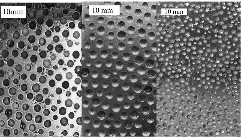
Figure 1 shows digital images from the sectioned samples
Element O Fe — — — —
[image:2.595.46.291.83.281.2]of the Al-LC cast foam as well as the 3.7 mm LC foam and 1.4 mm LC foam produced by PM.
Monotonic compression testing of all materials demon-strated the typical behavior of an elastic-plastic foam under compression.4)There is an initial linear elastic region, which is followed by an extended region of deformation at a relatively constant level of stress. Unlike most foams, however, these materials do not exhibit a level plateau stress. The material densifies at a slowly increasing rate and there is no distinct point at which full densification occurs. For this paper, the plateau stress has been defined as the average stress from 0.2% (yield point) to 50% strain. All materials reached a minimum of 50% strain and had not yet reached full densification at that point. Figure 2 shows the stress-strain curves of various composite foams under monotonic com-pression. After 50% strain, the foams begin to approach densification as the hollow spheres are completely collapsed and the material begins to behave like a bulk material. The physical properties of the foams processed using both techniques are shown in Table 2.
3.1 Cast foam
The cast sample had a density of 2.4 g/cm3 (42% relative
density). During monotonic compression, this foam reached an average plateau stress of 67 MPa up to 50% strain, before it began densification around 50% strain.
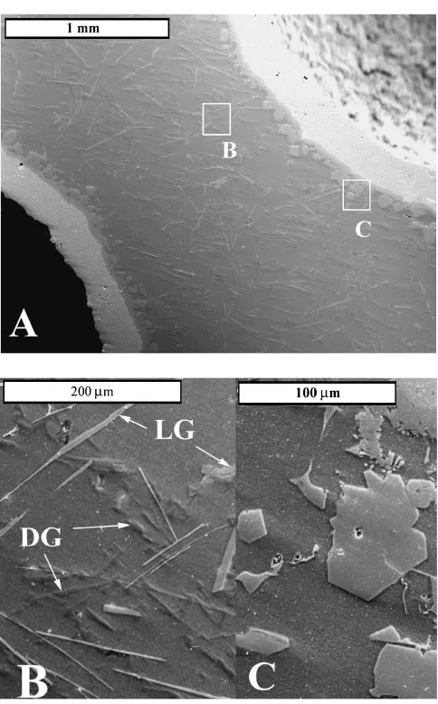
Optical and SEM observation was used to determine how well the spheres had bonded with the matrix material. It was determined that the matrix had nearly filled all of the vacancies between the spheres (Fig. 3(a)). It has been calculated that there is less than 1% void space due to the aluminum failing to completely fill the interstitial spaces between the point contacts of the spheres.13)
SEM images showed different phases present in the matrix. SEM-EDX compositional analysis was performed to differentiate the phases. The sphere walls were verified to be nearly 100% iron. The matrix was found to be nearly 98% aluminum, with the remainder being silicon and trace elements. The compositions of the other phases are shown in Table 3. Figures 3(b) and 3(c) show the other phases that are present within the matrix.
Microhardness testing was performed on all various components and phases present in the cast samples. Accurate readings could not be taken for the light and dark needle shaped phases due to their small size. These results are shown in Table 3. Two different phases were identified as present within the matrix- the light gray phase and the dark gray phase. The light gray phase, a ternary alloy of Al with Si and Fe, estimated to be Al4FeSi from the Al-Fe-Si ternary phase
diagram19) was found in two different shapes-plates and
needles. Binary Al-Si alloys with increased iron content form hard, brittle plates of the compound -AlFeSi and with controlled iron content form the finer-AlFeSi compound.20) The plate shaped light gray phase found concentrated around the sphere walls as shown in Fig. 3(c) is the hard-AlFeSi compound (Table 3) whose formation was facilitated by the diffusion of iron from the sphere walls into the aluminum matrix. This is also the reason why the plate shaped light gray
Fig. 1 Cut sections of the composite Al-steel cast foam, 3.7 mm and 1.4 mm composite steel-steel PM foam (from left to right).
[image:3.595.101.500.71.297.2] [image:3.595.63.277.351.499.2]phase is always present only in the immediate vicinity of the spheres, as its formation requires higher iron content along with aluminum and silicon available only at the sphere-matrix interface. The diffusion of iron from sphere walls into the aluminum matrix as well as the diffusion of silicon from
the matrix to the sphere-matrix interface facilitates the precipitation of plate shaped light gray phase at the sphere-matrix interface. The needle shaped light gray phase within the matrix away from the sphere walls (Fig. 3(b)) is the finer and possibly softer -AlFeSi compound whose formation was facilitated by the controlled iron content, and also by presence of manganese20) and silicon which comprises the
composition of Al 356 alloy.
Slow solidification of a pure Al-Si alloy produces a very coarse microstructure in which the eutectic comprises of large plates or needles of Si in the continuous matrix, formed due to precipitation of silicon.20)The dark gray phase found in the matrix is primarily this eutectic of approximately 97% Si and 3% Al composition, formed due to the precipitation of Si from the solid solution at elevated temperatures. The flake-like shape of the dark gray phase is attributed to the highly anisotropic crystal growth in diamond cubic systems like silicon. The composition and hardness values of all the phases in the aluminum matrix are shown in Table 3. Microhardness test results show that the diffusion of iron from the spheres into the aluminum takes place leading to the precipitation of a hard plate-shaped light gray phase, subsequently strengthening the material.
3.2 PM Foam
Three different sets of foams have been produced using the PM technique. Two have been produced using LC steel powder with 3.7 and 1.4 mm low carbon steel spheres with similar matrix, and one 316L stainless steel powder and 2.0 mm stainless steel spheres. The first PM set of samples,
[image:4.595.50.550.83.259.2]Fig. 3 SEM image showing aluminum matrix in a cast sample (a) between two spheres, (b) Dark grey (DG) and light grey (LG) needle shaped phase, and (c) Light grey plate shaped phase in Al-LC steel cast composite foam.
Table 3 Compositional analysis and corresponding Vickers Hardness of phases in aluminum matrix (atomic %) in cast sample.
Feature Al Si Fe HV
Spheres — — 100 69.7
Aluminum matrix 97.9 2.6 Trace 45.1 Light grey plate
shapes phase 64.95 9.27 25.78 732.5 Light grey needle
[image:4.595.48.290.277.666.2] [image:4.595.306.550.305.403.2]produced with the 3.7 mm LC steel spheres, had a density of 3.0 g/cm3 (38% relative density). During monotonic
com-pression, this foam reached a plateau stress of 42.3 MPa before beginning densification around 55% strain.
The second set of LC steel PM samples, with the 1.4 mm spheres, had a density of 2.55 g/cm3 (34% relative density) and reached a plateau stress of 76 MPa during monotonic compression before it began densification around 50% strain. The 316L stainless steel PM sample, produced with 2.0 mm spheres, had a density of 2.9 g/cm3 (37% relative density)
and reached a plateau stress of 136 MPa up to 50% strain and began densification around 50% strain. Figure 4 shows the stainless steel foam before and after compression testing with 60% strain. These plateau stresses compare favorably to other hollow sphere foams with similar materials, which exhibit plateau stresses of 5 and 23 MPa.9–11)
SEM observation showed that the powder was able to completely fill up all spaces between spheres and SEM images show that the only distinction between the sphere walls and the sintered matrix is the visible density of porosities in the matrix (Figs. 5, 6).
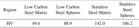
Microhardness was performed on the PM foams as well. Results are shown in Table 4. Due to the porosity of the matrix, there was difficulty in attaining accurate readings. Some indentations were greatly distorted and others were on edges of pores. Only readings where the indentation was able to be read accurately were used to calculate the average. Although the matrix is made of the same material as the spheres in both cases, the spheres averaged about 40 HV harder than the matrix. The lower hardness of the matrix is due to the greater amount of porosity within the matrix.
The energy absorbing capabilities of the new foams are superior to those of other hollow sphere foams. Most of the new foams were able to absorb almost 2–4 times more energy than the other foams,12) with the stainless steel PM foam having an energy absorbing capability almost 7 times greater than foams made from similar materials through different techniques. Because the foams begin densification at differ-ent strains, it was decided to compare them all at 50% strain.
Due to the sintering temperature and vacuum level, there was some concern that the chromium in the stainless steel powder would evaporate, reducing the corrosion resistance capability of the matrix for the stainless steel foams.15)SEM EDX was performed on the sintered matrix and it was found that the composition of the stainless steel was within the nominal composition of the powder as given by the manufacturer (Table 1).
Fig. 4 Photographs of the PM stainless steel composite foam before (left)
and after (right) monotonic compression of 60%. Fig. 5dashed line showing the wall thickness of one sphere (note that the cut isSEM image of 1.4 mm hollow sphere LC steel composite foam with not through the center of the spheres).
[image:5.595.51.288.70.258.2]Fig. 6 SEM image of 2.0 mm 316L stainless steel composite foam showing porosity difference in sphere walls and matrix, with dashed line showing the wall thickness of one sphere.
Table 4 Vickers Hardness of different regions in the LC and stainless steel PM foams.
Region Low Carbon Steel Matrix
Low Carbon Steel Spheres
Stainless Steel Matrix
[image:5.595.307.548.72.261.2] [image:5.595.307.548.331.521.2] [image:5.595.305.549.617.666.2]# 0238929.
REFERENCES
1) J. Banhart and W. Brinkers: Journal of Material Science Letters18
(1999) 617–619.
2) Y. Sugimura, A. Rabiei, A. G. Evans, A. M. Harte and N. A. Fleck: Mater. Sci. Eng. A269(1999) 38–48.
3) A. Rabiei, A. G. Evans and J. W. Hutchinson: Metall. and Mater. Trans.
31A(2000) 1129–1136.
4) Y. Sugimura, J. Meyer, M. Y. He, H. Bart-Smith, J. Grenstedt and
13) A. Rabiei and A. T. O’Neill: Mater. Sci. Eng. A404(2005) 159–164. 14) B. P. Neville and A. Rabiei: Mater. Sci. Eng. A, 2006.
15) ASM Metals Handbook, 9th, American Society for Metals, 1984. 16) N. Dautzenberg and J. Hewing: Powder Metallurgy International, 9,
1977.
17) L. Forss: Perspectives in Powder Metallurgy, (Plenum Press, New York, 1968).
18) R. M. German:Powder Metallurgy of Iron and Steel, (John Wiley and Sons, New York, 1998).
19) P. Villars, A. Prince and H. Okamoto:Handbook of Ternary Alloy Phase Diagrams, (1995).