Experimental Determination of Forming Limit Diagram
and Springback Characteristics of AZ31B Mg Alloy Sheets
at Elevated Temperatures
Hyung Jong Kim
1, Sun Chul Choi
2, Kyoung Taek Lee
3and Heon Young Kim
11Division of Mechanical Engineering & Mechatronics, Kangwon National University,
192-1 Hyoja 2-Dong, Chuncheon, Gangwon-Do 200-701, Korea
2Graduate School, Kangwon National University, 192-1 Hyoja 2-Dong, Chuncheon, Gangwon-Do 200-701, Korea 3Technical Center, AUSTEM Co., Ltd, 173-299 Kajwa-Dong, Seo-Gu, Incheon-Si 404-250, Korea
A warm/hot formability testing apparatus was designed and fabricated for this study. The forming limit curve (FLC) and springback characteristics of AZ31B Mg alloy sheets at elevated temperatures of up to 300C were investigated. The forming limit increased rapidly with
temperature up to 200C, and increased slightly thereafter. In the range from 200 to 300C, the FLC
0was found to be six to seven times higher
than at room temperature. In isothermal springback tests, the effect of the blank holding force (BHF) on springback differed slightly from that for other metal sheets at low temperatures. At 200C and above, negligible springback was observed over the range of BHF’s used. With increasing
temperatures, springback decreased rapidly up to 200C, and very slowly afterward. In nonisothermal tests, considerable springback was
observed, even at temperatures of 200C or higher; furthermore, it decreased almost linearly with increases in both the temperature and
BHF. [doi:10.2320/matertrans.MC200778]
(Received October 18, 2007; Accepted February 19, 2008; Published April 2, 2008)
Keywords: AZ31B magnesium alloy sheet, forming limit diagram, springback, punch stretching, 2D draw bending
1. Introduction
Magnesium is a fairly strong and light-weight metal, with a density that is one-fourth that of steel and two-thirds that of aluminum. However, when alloyed with other metals, it has an excellent strength-to-weight ratio and shows outstanding performance in terms of machinability, vibration absorption, and electromagnetic shielding. These features have drawn attention to magnesium as a useful material for various electronic parts and structural applications. Magnesium alloys usually exhibit very poor workability and formability at room temperature because of their hexagonal close-packed (HCP) structure, but the forming limit can be considerably
increased at elevated temperatures.1) Conventionally, die
casting or squeeze casting is used for manufacturing magnesium alloy parts. These processes, however, require heating materials in the liquid or semisolid state, which may result in casting defects and finally cause safety problems. Recently, warm or hot press-forming technology for magne-sium alloy sheets has been recognized as a promising alternative. However, there still are difficulties involved in controlling the process parameters such as the forming speed and temperature since magnesium has a low heat capacity. Most of the studies on magnesium alloy sheet forming at elevated temperatures have focused on the formability, and only few on the springback characteristics.
Zhang et al.,2) Yoshihara et al.,3) and Huang et al.4)
conducted experimental investigations and numerical analy-ses on the formability and the effect of the blank holding
force (BHF) during a deep drawing process. Naka et al.5)
produced the forming limit diagram (FLD) of JIS-A5083 Al–Mg alloy for various temperatures and strain-rates. Chen et al.6)evaluated the formability of AZ31B magnesium alloy sheets through conical cup and V-bending tests. Bruniet al.7) carried out air bending tests to investigate the springback
characteristics at different temperatures. Kimet al.8)reported on the springback characteristics of AZ31B magnesium alloy sheets in draw bend tests at room temperature, and Leeet al.9) proposed a constitutive equation for the same material.
Recently the authors10)have performed some experiments to
investigate the change in the forming limit and the spring-back characteristics of the same material with an increase in temperature. Many studies on magnesium alloy sheets have shown that it has significantly greater formability at
temper-atures above 200C than at lower temperatures in various
sheet forming processes.
The limit strains are represented best by the concept of a forming limit curve (FLC), which shows the onset of localized necking over all possible combinations of surface
strains in the sheet.11) FLD’s are usually obtained by two
methods: the out-of-plane deformation test using a
hemi-spherical punch, proposed by Hecker;12) or the in-plane
deformation test using a flat-headed punch with a circular cutout in the center, developed by Marciniak.13)
Springback occurs due to the elastic recovery after sheet metal stamping operations, affecting dimensional accuracy, assembly tolerance, and appearance to a great extent. Therefore, it has been one of the most frequently studied
issues over the past scores of years.14–16) The 2D draw
bending test was adopted by NUMISHEET ’93 Conference17)
as a benchmark problem, aiming at the comparison between numerical (finite element) prediction and experimental measurement on the basis of the geometric definition of the springback quantity. Since the blank is not constrained by its configuration in this test, it undergoes considerable elastic recovery. This test allows the application of various BHF’s. In the present study, punch stretching tests and 2D draw bending tests were carried out with AZ31B magnesium alloy sheets to obtain the FLD and to investigate the springback characteristics at elevated temperatures. It is known that
at high punch speed of 200 mm/min the level of the FLD for elevated temperatures is as low as that for the room
temperature.5) In this study, however, all the tests were
performed at very low deformation speed so that the effect of strain-rate on the FLD and springback might not be dominant. The goal of the current work is to set up an experimental methodology and to provide reliable material data for die and process designers.
2. Forming Limit Diagram
2.1 Punch stretching test
Figure 1 shows a double-acting press, which has two hydraulic cylinders of 50-ton capacity each. An electric furnace and a temperature control unit for heating the die set and blank to the desired temperature were set up on the bed.
Alternatively, heating cartridges of proper capacity were inserted in each tool, enabling heating of the die set and blank directly without the furnace. All the tests were conducted using this direct heating method, which could maintain the temperature more stably. A schematic of the hemispherical punch stretching apparatus is illustrated in Fig. 2, showing the location of the heating cartridges as well as the dimensions of the tools. The main dimensions were the
same as those of the NUMISHEET ’9618) benchmark
problem.
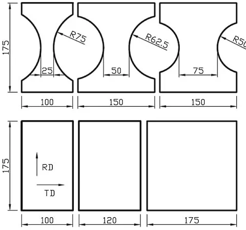
FLD test specimens having the same length (in rolling direction) of 175 mm and seven different widths in the range from 25 to 175 mm were cut into the shapes shown in Fig. 3 from a 0.5-mm-thick AZ31B sheet. It was found helpful to
(b)
Fig. 1 Photo of hot formability testing equipment with (a) punch stretching tools and (b) 2D draw bending tools.
Fig. 2 Schematic diagram of punch stretching test apparatus for FLC measurements.
[image:2.595.70.264.71.541.2] [image:2.595.304.547.72.306.2] [image:2.595.304.544.358.582.2]provide a circular cutout on both sides of the specimens narrower than 75 mm in order to avoid wrinkling around the punch and fracture in the clamping bead.10,11)All specimens
were gridded with 33mm squares to permit strain
measurement. The grids were printed onto each specimen using a silk-screen technique with a very accurate negative, instead of an electrochemical etching method. This was because etched grids might act as initial imperfections in the thin sheets: several pretest specimens showed that etched grids led to premature failure and, consequently, a drop in the forming limit. No lubrication was used between the punch and blank for most tests. To induce fracture in the balanced biaxial mode, a water-soluble graphite lubricant was applied
on the punch surface prior to the test with the175175mm
specimen. Tests were performed at temperatures of 25, 100,
200, 250, and 300C and at a constant punch speed of
0.1 mm/s.
2.2 FLD test results and discussion
For reliable measurement of strains around localized
necks, ‘‘ASIAS’’19) was used; it is an automated
surface-strain measurement system developed by the authors by using image processing and stereo vision techniques. Recent improvements in ASIAS have enabled it to process high-resolution images of eight megapixels or above, and to measure strains to an accuracy of0:17%.
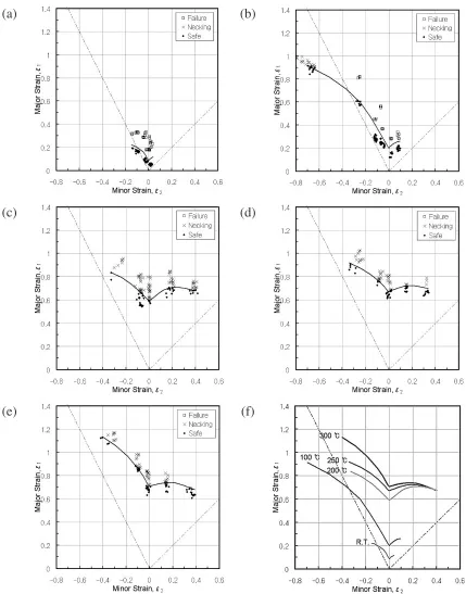
Figure 4 is a photo of the test specimens formed at 250C. The enlarged photos show the fractures or localized necks clearly. Figures 5(a)–(e) show the construction process of the
FLC’s for 25, 100, 200, 250, and 300C, respectively, and
Fig. 5(f) compares them with each other. These figures show that the higher the temperature, the higher the forming limit, as can be predicted from the stress-strain curves for various temperatures shown in Fig. 6.
The FLC0 of the AZ31B sheet increased rapidly up to a
temperature of 200C, and thereafter increased slowly up to
300C, at which it reached a value seven times that at room
temperature. It is known that the considerable increase in formability at temperatures slightly higher than 200C is due
to the thermal activation of the pyramid sliding planes in the hexagonal structure.20)
The limit minor strains measured for specimens of even the same width varied extensively with temperature. For
exam-ple, the minor strains obtained for the 25-mm-wide
speci-mens ranged from 0:15 at room temperature to 0:7 at
100C, and those for the 175-mm-wide lubricated specimens
ranged from 0.04 at room temperature to 0.4 at 200 and
300C. It is remarkable but not understood that the strain
state in the 25-mm-wide specimen at 100C is far beyond the
uniaxial tension mode, and approaching the pure shear mode. One possible explanation is that a change in the aggregated structure of the AZ31B sheet around this temperature causes its normal anisotropy to increase abruptly.
The graphite lubricant used for the warm/hot forming processes did not exhibit an effect as good as that achieved by a polyurethane membrane coated on both sides with mineral oil or beef tallow, which is usually used for cold FLD tests. This made it impossible to obtain the limit strains under balanced biaxial tension.
In the tests at 25 and 100C, brittle fracture occurred
suddenly during the forming processes, and it was very hard to stop the punch at the very moment of local necking. This gave rise to significant differences between the safe and necking (or failure) zones in the obtained FLD’s. In the tests at 200C and above, on the other hand, it was comparatively
easy to find the point of local necking from the punch load– displacement graph and also to stop the punch, enabling accurate plotting of the FLC along the boundary between the safe and necking zones. As shown in Figs. 5(c)–(e), the major strains of necked grids are scattered over a band with a maximum width of 0.2, indicating that the post-necking strain was fairly large due to the increase in the strain-rate sensitivity at elevated temperatures.
3. Springback Characteristics
3.1 2D draw bending test
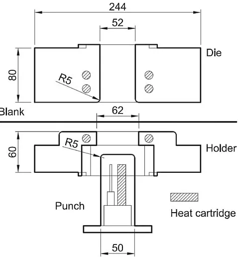
To evaluate the springback characteristics of AZ31B magnesium alloy sheets, 2D draw bending tests were con-ducted as described in the NUMISHEET ’93 benchmark. The test apparatus is illustrated in Fig. 7. Each test specimen was rectangular in shape, with a length of 350 mm (in rolling direction), width of 35 mm, and thickness of 1.0 mm.
The forming temperatures were set to 25, 100, 200, 250,
and 300C—the same as in the FLD tests—using the direct
heating method. Tests were focused on the influence of the
[image:3.595.85.512.73.228.2]BHF as well as temperature on the springback character-istics. The BHF was determined to be 30 to 250 kgf from preliminary tests. To control such small BHF’s, a screw-type blank holding device and a load cell with a 2-ton capacity were attached to the test apparatus, as shown in Fig. 1(b). The punch speed and its final stroke were kept constant at 1.0 mm/s and 70 mm, respectively, for all the tests.
The tests were divided into two categories: the isother-mal tests, wherein the punch, die, and blank holder were heated to and maintained at the same temperature; and the nonisothermal tests, wherein only the die and blank holder
were heated while the punch remained at a much lower temperature.
3.2 Springback test results and discussion
The springback angles 1 and 2, defined in Fig. 8,
quantify the extent of elastic recovery of a test blank. It can be said that the larger the value of1and the smaller the value
of2, the greater the springback that occurs, and both angles
would remain right angles without springback. These angles were measured using a CAD software from scanned images of either side of a deformed specimen.
(c) (d)
(e) (f)
[image:4.595.83.512.68.615.2]3.2.1 Isothermal test
[image:5.595.48.289.70.247.2]The isothermal tests were conducted after thermal equi-librium at a given temperature was achieved by controlling the heating units of the punch, die, and blank holder simultaneously. Figure 9(a) shows a photo of the test spec-imens deformed at different temperatures. The springback angles for various temperature and BHF combinations are tabulated in Table 1. Figure 10 illustrates the effect of the BHF on the springback angles for different temperatures, and Fig. 11 the relationship of the springback angles to the temperature for various BHF’s. It is well known that as the BHF increases, springback usually tends to be smaller, or in
other words, 1 is smaller and 2 is larger. However, the
magnesium alloy sheet used in this study exhibited character-istics different from those of other metals, especially at low temperatures. An increase in the BHF led to an increase in both1 and2 at 25C, but a decrease in both1 and2 at
100C. This is similar to the results of a cold draw bend test
Fig. 7 Schematic diagram of 2D draw bending test apparatus for spring-back measurements.
Fig. 8 Definition of springback angles. Fig. 6 Stress-strain curves at various temperatures.
(a)
(b)
[image:5.595.308.547.71.329.2] [image:5.595.305.548.383.482.2] [image:5.595.107.490.530.767.2]by Kimet al.,8)wherein springback increased until the load
reached a certain value and decreased once the back-tension exceeded the limit. On the other hand, at temperatures above 200C, springback scarcely occurred, regardless of the BHF.
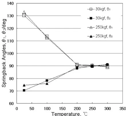
The effect of temperature on springback, as shown in Fig. 11, was very similar to that on the forming limit; that is,
springback decreased rapidly up to 200C, but subsequently
continued decreasing very slowly. The decrease in spring-back with increasing temperature is mostly because of
the decrease in flow stress with increasing temperature as shown in Fig. 6.
3.2.2 Nonisothermal test
In the nonisothermal tests, the die and blank holder were heated to the desired temperature but not the punch. This test aimed to simulate the deep drawing process, wherein the punch was cooled in order to improve formability. The temperatures of the die and blank holder were set to 200,
250, and 300C. In each case, the punch temperature was
maintained at 100, 110, and 120C, respectively. Of course,
a slight rise in the punch temperature due to thermal conduction was inevitable, requiring a pause for cooling the punch between two successive tests.
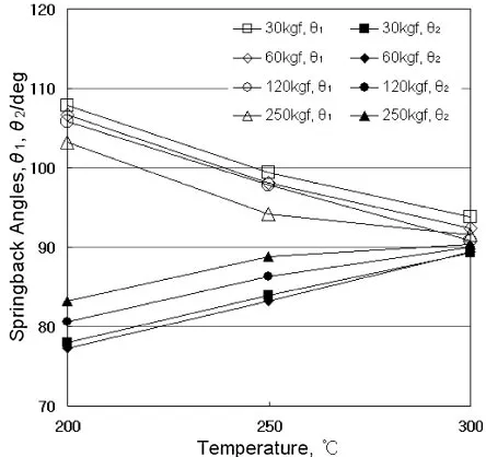
Figure 9(b) is a photo of the test specimens, and Table 2 lists the measured springback angles. The changes in the springback angles with the BHF and temperature are dis-played in Fig. 12 and Fig. 13, respectively. These figures and the table clearly show that springback occurred even at
temperatures of 200C or higher, unlike in the isothermal
tests: with increasing temperature and BHF, springback decreased almost linearly. Therefore, when cooling or not heating the punch to improve formability, the springback at elevated temperatures must be properly taken into consid-eration for the design of the forming process and tools.
4. Conclusion
A double-acting hydraulic press equipped with heating and temperature control units was designed and fabricated for this study. The forming limit and springback character-istics of AZ31B magnesium alloy sheets at elevated temper-atures were investigated extensively. The test results are summarized as follows:
(1) The forming limit increased sharply with temperature
up to 200C, around which the sliding planes were
activated; and thereafter, the increasing trend slowed
down. In the range from 200 to 300C, the commonly
used range of forming temperatures for magnesium
(a)
[image:6.595.315.535.70.273.2](b)
[image:6.595.45.291.84.211.2]Fig. 10 Variation of springback angles with BHF in isothermal tests.
[image:6.595.56.279.234.642.2]alloy sheets, the FLC0 was found to be six to seven
times higher than that at room temperature.
(2) The limit minor strains, despite being measured from specimens of the same width, ranged over an extensive area in the FLD’s, depending on the temperature. It is remarkable but not understood that the limit strain state
in the 25-mm-wide specimen at 100C was close to the
pure shear mode, far beyond the uniaxial tension mode, unlike that at other temperatures.
(3) In the isothermal tests, where not only the die and blank holder but also the punch were heated up to the same temperature, an increase in the BHF led to an increase in both1and2at 25C, but a decrease in both1and
2 at 100C. This feature differs slightly from that of
other metal sheets. At 200C or above, springback was
observed to be ignorable in the range of BHF’s used. As for the effect of temperature, springback decreased rapidly up to 200C, and very slowly afterward.
(4) In case of the nonisothermal tests, wherein the punch was not heated, considerable springback occurred even
at temperatures of 200C or higher. With an increase
in the temperature and BHF, springback decreased almost linearly. Therefore, in the case of cooling or not heating the punch to improve formability, the spring-back at elevated temperatures must be taken into consideration for proper design of the forming process and tools.
Acknowledgment
This study was supported by the Research Grant from Kangwon National University.
REFERENCES
1) H. Watanabe, H. Tsutsui, M. Kohzu, S. Tnabe and K. Higashi: Int. J. Plasticity17(2001) 387–397.
2) S. H. Zhang, K. Zhang, Y. C. Xu, Z. T. Wang, Y. Xu and Z. G. Wang: J. Mat. Proc. Tech.185(2007) 147–151.
3) S. Yoshihara, K. Manabe and H. Nishimura: J. Mat. Proc. Tech.170
(2005) 579–585.
4) T. B. Huang, Y. A. Tsai and F. K. Chen: J. Mat. Proc. Tech.177(2006) 142–145.
5) T. Naka, G. Torikai, R. Hino and F. Yoshida: J. Mat. Proc. Tech.113
(2001) 648–653.
6) F. K. Chen and T. B. Huang: J. Mat. Proc. Tech. 142 (2003) 643–647.
7) C. Bruni, A. Forcellese, F. Gabrielli and M. Simoncini: J. Mat. Proc. Tech.177(2006) 373–376.
(a)
[image:7.595.314.536.72.281.2](b)
[image:7.595.46.290.85.209.2]Fig. 12 Variation of springback angles with BHF in nonisothermal tests.
Fig. 13 Variation of springback angles with temperature in nonisothermal tests.
Table 2 Measured data of springback angles in nonisothermal tests. BHF,
kgf
Angle, deg
Die 200C
Punch 100C
Die 250C
Punch 110C
Die 300C
Punch 120C
30 1 107.9 99.4 93.8
2 78.0 83.9 89.3
60 1 106.7 98.1 92.4
2 77.2 83.2 89.4
120 1 105.8 97.9 90.9
2 80.5 86.3 90.1
250 1 103.2 94.2 91.5
[image:7.595.56.279.236.641.2]