Growth Manner of Intermetallic Compound Layer Produced at Welding Interface
of Friction Stir Spot Welded Aluminum/Steel Lap Joint
*1Mitsuhiro Watanabe
1;*2, Keyan Feng
2;*3, Yoshio Nakamura
1and Shinji Kumai
21Department of Metallurgy and Ceramics Science, Tokyo Institute of Technology, Tokyo 152-8552, Japan 2Department of Materials Science and Engineering, Tokyo Institute of Technology, Yokohama 226-8502, Japan
Lap joining of a pure aluminum plate and a low carbon steel plate was performed using friction stir spot welding. The aluminum plate was placed over the steel plate, a rotating welding tool was inserted into the aluminum plate, and the tip of the tool was dwelled above the aluminum/ steel interface. Dwell time was controlled in the range of 0 to 120 seconds. The microstructure of the welding interface was examined by optical microscopy and scanning electron microscopy. Chemical composition analysis was carried out by energy dispersive X-ray spectroscopy. Welding was achieved for all dwell times. Refined grains were formed by plastic flow in the aluminum matrix close to the welding interface. Intermetallic compound layer was produced along the welding interface. Precise backscattered electron image observation and energy dispersive
X-ray spectroscopy analysis revealed that the intermetallic compound layer consisted of an Al13Fe4phase layer and an Al5Fe2phase layer. The
thickness of the layers increased in proportion to the square root of the dwell time. The parabolic coefficient K was1:301014 and
6:061013m2/s for the Al13Fe4layer and the Al5Fe2layer, respectively. [doi:10.2320/matertrans.L-MZ201120]
(Received October 1, 2010; Accepted February 2, 2011; Published April 13, 2011)
Keywords: friction stir spot welding, aluminum, steel, intermetallic compound, growth manner
1. Introduction
The transportation industries are increasingly using alu-minum plates because a light-weight material is required to achieve lower CO2 emissions. A key issue for the
develop-ment of reliable aluminum plate and steel plate hybrid structures is their welding. Several welding methods, such as diffusion bonding, roll bonding, friction welding, friction stir welding, and magnetic pulse welding have so far been attempted in order to obtain a strong joint.1–5) However,
sound joints with acceptable strength have not yet been obtained because of the formation of a thick and brittle Al-Fe intermetallic compound (IMC) layer at the welding interface and degradation of strength of the base materials because of additional adverse thermal effects.6,7)Therefore, controlling
the formation of IMC layers is important for obtain a reliable joint.
Friction stir spot welding is derived from friction stir welding, which is a widely used solid-state welding method for aluminum alloys.8) This welding method is attracting much interest from the automotive industry as an alternative to the conventional arc spot welding. In case of aluminum/ steel lap joining, the rotating welding tool is plunged into the aluminum plate to the specified depth and it is dwelled at a set time. The welding is completed by withdrawing the tool from the plate. This process is used to weld two materials, and utilizes the plastic flow induced by the inserted rotating tool and friction heat generated between the plate surface and the rotating tool. Since this method is a kind of the solid-state welding, it should be possible to control the thickness of IMC layer.
In the present study, the lap joining of an aluminum plate and a steel plate was performed using friction stir spot
welding. The interfacial microstructure of the joint, in particular, the IMC layer produced at the welding interface, was examined. By changing the dwell time, the growth manner of the IMC layer was investigated.
2. Experimental Procedures
2.1 Materials and welding conditions
A commercial purity aluminum (99.50 mass%Al) plate and a low carbon steel (99.82 mass%Fe) plate were used. The dimensions of the plates were 30 mm (length)100 mm (width)1.0 mm (thickness). Figures 1(a) and (b) show optical micrographs of the grain structure of the original plates. The average grain size was 15mmfor the aluminum plate and 20mm for the steel plate. The plate surfaces subjected to lap welding were mechanically polished using waterproof abrasive paper and then washed with acetone in an ultrasonic cleaner.
Spot welding was carried out using a vertical-type milling machine. The welding tool was made of SKH51 high-speed tool steel, and consisted of a cylindrical shoulder and probe. The shoulder diameter, the probe diameter, and the probe length were 10 mm, 5 mm, and 0.7 mm, respectively. Vertical grooves (depth: 0.2 mm, pitch: 1.0 mm) were introduced to the probe surface.
Figure 2 shows a schematic illustration of the present welding method. The aluminum plate was placed on the steel plate, and the lapped specimen was fixed on a cast steel table. Welding was conducted by inserting the rotating welding tool into the aluminum plate. The rotational speed and plunge speed of the tool were 3000 rpm and 6:7105m/s,
respectively. The plunge depth of the tool was set to 0.8 mm from the aluminum plate surface so that the probe tip was located above 0.2 mm away from the aluminum/steel inter-face, as shown in Fig. 2. The dwell time is defined as the length of time that the probe tip is located 0.2 mm above the lapped interface. The dwell time was changed from 0 to 120 s.
*1The Paper Contains Partial Overlap with the ICAA12 Proceedings by
USB under the Permission of the Editorial Committee.
*2Present address: Interdisciplinary Graduate School of Medicine and
Engineering, University of Yamanashi, Kofu 400-8511, Japan
*3Graduate Student, Tokyo Institute of Technology
Special Issue on Aluminium Alloys 2010
2.2 Temperature measurements
The temperature generated at the aluminum/steel interface was measured using K-type thermocouples during welding. The tips of the thermocouples were located at the aluminum/ steel interface. The temperature measurements were con-ducted at both the central position and outer region of the probe, as shown in Fig. 3.
2.3 Evaluation of lap joint strength
The welding strength of the lap joints was examined by cross tension tests. Both the aluminum and steel plates (30mm100mm1:0mm) were cross-overlapped and friction stir spot welding was carried out so that the welding
interface was perpendicular to the direction of the tensile load. The cross tension tests were performed at room temperature in air on an Instron-type testing machine with a constant crosshead speed of1:7105m/s.
2.4 Microstructural observation
The cross section of the lap joints was polished for microstructural observation of the welding interface. Inter-facial microstructure was examined by optical microscopy and field emission scanning electron microscopy (FE-SEM). In order to investigate morphological changes of the grains, the polished surface was chemically etched in solutions. The solutions are HF:H2O¼1 : 50in volume for the aluminum
grains and HNO3:C2H6O¼1 : 50 for the steel grains.
Chemical composition was analyzed by energy dispersive X-ray spectroscopy (EDS) equipped with FE-SEM.
3. Results
3.1 Temperature generated at the interface
Figure 4 shows the relationship between the temperatures generated at the aluminum/steel interface and the welding time. The welding time consists of the plunging time and dwell time. The start of the welding time (t¼0) is defined as the moment when the probe tip comes into contact with surface of the aluminum plate. The temperatures were measured at two positions that are interfaces under the probe and the shoulder, i.e., outer region of the probe. The temperature increased drastically during the plunging time (a)
(b)
Fig. 1 Optical micrographs of original grain structure. (a) Aluminum plate.
(b) Steel plate.
Shoulder
Probe Al
Steel
[mm] 0.2 Probe Al
Steel
Fig. 2 Schematic illustrations of friction stir spot welding process.
Al
Steel
Thermocouple
Fig. 3 Schematic illustration of thermo-couple setup.
200 300 400 500 600 700 800 900 1000
0 10 20 30 40 50 60 70 80 Plunging time
Dwell time
Probe center
Outer-region of probe
Welding time, t / s
T
emperature,
T
/ K
Fig. 4 Welding time dependency of temperature generated at the
[image:2.595.55.284.69.401.2] [image:2.595.353.501.73.181.2] [image:2.595.325.526.233.380.2] [image:2.595.60.275.451.584.2]and was constant during the dwell time. Under the present welding conditions, maximum temperature was 750 K at the central position of the probe and reached 700 K under the shoulder.
3.2 Macroscopic appearance and strength of the lap joint
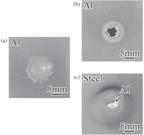
The typical macroscopic appearance of the upper surface of the aluminum plate after welding is shown in Fig. 5(a). A depression in the shape of the probe and the shoulder was formed in the aluminum plate. Burrs were also formed around the depression. Figures 5(b) and (c) show the external appearance of the fracture surface after the cross tension test.
For all dwell time tests, part of the aluminum plate having the size of the probe diameter adhered to the steel plate surface. This indicates that fracture did not take place at the welding interface but mainly occurred at periphery of the most thin aluminum plate matrix. This result was common for any dwell time.
3.3 Interfacial microstructure of the lap joint
A typical optical micrograph for the cross section of the lap joint welded with a dwell time of 20 s is shown in Fig. 6(a). The upper part is aluminum and the lower part is steel. The aluminum plate was deformed to trace the tool shape. Welding was achieved at the area under the probe, but not at the area under the shoulder. Figures 6(b) and (c) show optical micrographs of the grain structure of the aluminum matrix and the steel matrix close to the welding interface. The grain size of the aluminum close to the welding interface was smaller than that of the original matrix in Fig. 1. In contrast, the grain size of the steel close to the welding interface was similar to that of the matrix. It is found that grain refinement due to the stirring of the tool was achieved in the aluminum matrix, but not in the steel. This indicates that plastic flow took place only in the aluminum matrix. Figure 6(d) shows an optical micrograph of the welding interface. An IMC layer was produced along the welding interface. Formation area of the IMC layer was equivalent to the welded area. This indicates that the circular welded area was formed under the probe.
Figures 7(a) to (c) show backscattered electron images (BEIs, composition images) of the welding interface corre-sponding to positions A, B, and C in Fig. 6(a), respectively. The upper dark contrast area is aluminum and the lower bright contrast area is steel. The IMC layer with medium contrast was clearly observed between the aluminum and the steel. The thickness of the IMC layer was fairy consistent throughout the welding interface. Precise BEI observations revealed two different contrasts in the IMC layer. In order to identify the phase of the IMC layer, the chemical composi-(a)
(b)
(c)
Fig. 5 Macroscopic appearances. (a) Upper surface of the aluminum plate
of the lap joint. (b) Fracture surface of the aluminum plate after the cross tension test. (c) Fracture surface of the steel plate after the cross tension test.
A B C
(a)
(d) (c)
(b)
Fig. 6 (a) Optical micrographs of cross section of the lap joint (dwell time: 20 s). (b) Grain structure at the steel matrix close to the welding
[image:3.595.54.284.259.475.2] [image:3.595.83.515.554.760.2]tion profile across the IMC layer was measured for Al and Fe elements by SEM-EDS. Line analysis was performed normal to the welding interface, as shown in Fig. 8(a). The left-hand area is steel and the right-hand area is aluminum. A result for the lap joint welded with a dwell time of 20 s is shown in Fig. 8(b). The horizontal and vertical axes indicate the distance and the chemical composition, respectively. The solid and open symbols show the results for Al and Fe elements, respectively. The area between the broken lines corresponds to the IMC layer region. In the area of 0.3mm and more away from the broken lines, the chemical composition was similar to that of the matrices. On the other hand, the composition ratio of the IMC layer closer to aluminum matrix was Al:Fe¼3 : 1, and near the steel matrix it was Al:Fe¼5 : 2. These composition ratios mean that the double IMC layers at the welding interface consisted of an Al13Fe4 phase layer and an Al5Fe2 phase
layer.
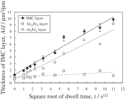
3.4 Effect of dwell time on thickness of IMC layer In order to investigate the growth manner of the IMC layer produced at the welding interface, the dwell time of the tool was changed from 0 to 120 s. Figure 9 shows the relationship between the welded area and the dwell time. The vertical axis shows diameter of the welded area since it was circular form. The diameter of the welded area increased slightly with increasing the dwell time. The thickness of the IMC layer also increased with increasing the dwell time, as shown in Fig. 10. As mentioned in Section 3.3, the Al13Fe4layer and
the Al5Fe2layer are produced at the welding interface for all
dwell times. From the cross-sectional BEIs, the average thickness of the each layer was evaluated by the following equation:
y¼A=D; ð1Þ
where y is the thickness of the IMC layer, A is the total area of the IMC layer, andDis the diameter of the welded area. This equation assumes that an IMC layer of constant thickness is produced throughout the welding interface. For all dwell times, ywas estimated from eq. (1) using values of A and D for various cross sections. The results for the IMC layer, the Al13Fe4 layer, and the Al5Fe2 layer are
plotted as solid diamonds, open circles, and open squares, respectively, in Fig. 11. In this figure, the vertical axis shows the layer thickness and the horizontal axis shows the square root of the dwell time. The thickness of the IMC layer increased in proportion to the square root of the dwell time.
(c) (b)
(a)
Fig. 7 BEIs of the welding interface which correspond to the positions in Fig. 6(a). (a) A, (b) B, and (c) C (dwell time: 20 s).
Distance, y / µm
Chemical composition / at%
0 10 20 30 40 50 60 70 80 90 100
0 1 2 3 4 5 6 7 8
IMC layer
Al Fe (a)
(b)
Fig. 8 (a) BEI of welding interface (dwell time: 20 s). Composition
analysis was performed along the white arrow. (b) Change in relative chemical composition of Al and Fe.
Dwell time, t / s
Diameter of welded area,
d
/ mm
3.0 3.5 4.0 4.5 5.0 5.5
0 10 20 30 40 50 60 70 80 90 100 110 120 130
[image:4.595.84.513.75.198.2] [image:4.595.63.279.239.500.2] [image:4.595.332.516.243.378.2]4. Discussion
4.1 Formation of the double IMC layer at the welding interface
In the present welding condition, the IMC layer was produced along the welding interface for all dwell times, as shown in Fig. 10. Precise BEI observation and SEM-EDS analysis revealed that the IMC layer at the welding interface consisted of an Al13Fe4phase layer adhering to the aluminum
and an Al5Fe2phase layer adhering to the steel. According to
the equilibrium phase diagram for a binary Al-Fe system,9)
Al13Fe4, Al5Fe2, Al2Fe, FeAl, and Fe3Al phases could all
appear as stable IMCs at an interfacial temperature of 750 K. However, Al2Fe, FeAl, and Fe3Al phases were not observed
in the welded joints at any of the dwell times in the present study. Shibata investigated the IMC layer produced at diffusion bonded aluminum/iron interface at a temperature range from 878 to 913 K.10)The main IMC layer was found to consist of an Al5Fe2phase. Naoi investigated the solid-state
reaction between pure aluminum and pure iron at a temper-ature range from 823 to 913 K using the equilibrium diffusion bonding technique.11)They detected only the Al5Fe2 phase
layer at the interface in the diffusion couples. However, they concluded that Al2Fe, FeAl, and Fe3Al phases could not grow
2 s
10 s
60 s
0 s
3 s
20 s
90 s
1 s
5 s
30 s
120 s
[image:5.595.83.513.68.600.2]1
µ
m
to a visible thickness because nucleation and growth of Al2Fe, FeAl, and Fe3Al phases may be much slower than for
Al13Fe4and Al5Fe2phases. Under the non-equilibrium state,
limited nucleation and growth of IMC phases were detected. Oikawa reported that Al3Fe, Al5Fe2, and Al2Fe phases were
formed along a hot rolled aluminum/steel interface.2) Yamamoto examined the IMC layer produced at the pure aluminum/mild steel interface by friction welding, and observed only the Al5Fe2 phase.12) Recently, Tanaka
re-vealed that an extremely thin amorphous layer of Al, Fe, and O was produced at a friction stir spot welded aluminum alloy/steel interface.13) Chen reported that only an Al
3Fe
phase layer was produced along the welding interface of a friction stir spot welded aluminum alloy/steel joint.14)These
experimental results indicate that the formation manner of the IMC phase is strongly affected by aspects of the welding process such as plastic flow, plastic deformation of the matrices close to the welding interface, and heating and cooling rates.
As mentioned above, Al-rich IMC phases such as Al13Fe4,
Al5Fe2, and Al2Fe are produced at the solid-state welded
aluminum/steel interface. In the present study, Al13Fe4 and
Al5Fe2phases were produced along the welding interface, as
shown in Fig. 8. This is considered to be because of a difference in solid-state diffusion coefficients.15)The
diffu-sion coefficient of iron into aluminum is 0 at temperatures up to about 673 K but it is much larger at temperatures greater than 673 K. In contrast, the diffusion coefficient of aluminum into iron is 0 at temperatures up to 1073 K. Therefore, diffusion of iron into aluminum takes place at temperatures below the melting point of aluminum (933 K), and diffusion of aluminum into iron does not take place. Consequently, Al-rich IMC phases are considered to be produced at the welding interface during solid-state joining.
It is known that oxide films on the surface of the aluminum plate prevent atomic diffusion.16,17) In case of equilibrium diffusion bonding, welding requires a long period of anneal-ing at high temperatures. However, we achieved friction stir spot welding with a dwell time of 0 s. This means that the oxide film on the aluminum plate surface was broken by the plastic flow during the plunging process. In the present study,
grain refinement was observed at the aluminum matrix close to the welding interface, as shown in Fig. 6(c). This indicates that plastic flow took place in the aluminum matrix close to the welding interface. These results show that the oxide film on the aluminum plate surface does not influence weldability and formation of the IMC layer.
[image:6.595.67.271.72.236.2]4.2 Growth manner of the IMC layer during dwell time The IMC layer was produced along the welding interface for all dwell times. The thickness of the IMC layer increased in proportion to the square root of the dwell time, as shown in Fig. 11.
When a new reaction phase is formed by diffusion between different metals or phases, the following equation has been proposed for the thickness of the new reaction phase,y, as a function of diffusion time,t.18,19)
y¼ ðKtÞ1=2 ð2Þ
Here, K is the parabolic coefficient, which represents the growth rate of the reaction phase. According to this equation, the thickness of the reaction phase is proportional to the square root of diffusion time. In this welding process, the dwell time of the tool is equivalent to the diffusion time because an isothermal reaction takes place during the dwell time (Fig. 4). Therefore, it can be concluded that the growth of the IMC layer is diffusion-controlled.
The thickness of the Al13Fe4 layer and the Al5Fe2 layer
also increased proportionally to the square root of the dwell time, as shown in Fig. 11. However, the growth rate was behaved differently. From the plotted points in Fig. 11, K was evaluated by the least-squares method to beK¼1:30 1014 and6:061013m2/s for the Al
13Fe4 layer and the
Al5Fe2 layer, respectively. The value of K has previously
been investigated at a wide temperature range.10,11,20–22)
Figure 12 shows previously reported values of K for the Al5Fe2 layer (open plots) and value reported in the present
study (solid squares) plotted against the respective temper-ature. These values are scattered in a wide range from1016 to1013m2/s at solid-state temperature range, showing that there is no agreement of the value ofKin the reported data so far. The present K value was higher than that of the solid-state diffusion couple, although it was lower than that of a liquid-aluminum/solid-iron joint.
Square root of dwell time, t / s1/2
Thickness of IMC layer
,
A/d
/
µ
m
2/µ
m 0 1 2 3 4 5 6 7 8 9 10 11
0 1 2 3 4 5 6 7 8 9 10 11 12 IMC layer
[image:6.595.323.529.74.204.2]Al13Fe4layer Al5Fe2layer
Fig. 11 Dwell time dependency of thickness of the IMC layer.
1.00E-16 1.00E-15 1.00E-14 1.00E-13 1.00E-12 1.00E-11 1.00E-10 1.00E-09 1.00E-08
700 750 800 850 900 950 1000 1050 1100 Present work
Naoi et al.11)
Shibata et al.10)
Jindalet al.21)
Tanaka et al.22)
Bouayad et al.20)
Temperature, T / K
P arabolic coef ficient, K / m 2/s
Fig. 12 Relationship between the temperature and value of parabolic
In the present welding method, the aluminum matrix is continuously stirred by a rotating welding tool, which achieves grain refinement. Evidence of the grain refinement of the aluminum was obtained in the aluminum matrix close to the welding interface, as shown in Fig. 6(c). This means that plastic flow takes place in the aluminum matrix close to the welding interface. The plastic flow results in crystal defects such as grain boundaries, dislocations, and vacancies. The crystal defects can enhance the atomic diffusion, like pipe diffusion mechanism.23,24) The present enhanced dif-fusion is considered to be due to existence of the defect structure formed along the welding interface.
5. Conclusions
Lap joining of an aluminum plate and a steel plate was carried out using friction stir spot welding. The rotating tool was inserted into the aluminum plate placed on the steel plate, and the tip of the tool was held 0.2 mm above the aluminum/steel interface for a specified dwell time. The growth manner of the IMC layer produced along the welding interface was investigated by changing the dwell time. The results are summarized as follows.
(1) The temperature at the aluminum/steel interface in-creased drastically during plunging of the tool and was constant during the dwell time. For the central position of the probe corresponding to the welded area, the maximum temperature was 750 K.
(2) Grain refinement due to the stirring of the tool was achieved in the aluminum matrix but not in the steel matrix, indicating that plastic flow took place only in the aluminum matrix.
(3) Double IMC layers, which consisted of an Al13Fe4
phase layer adhering to the aluminum and an Al5Fe2
phase layer adhering to the steel were produced along the welding interface at all dwell times. The thicknesses of the Al13Fe4 and Al5Fe2 layers increased in
propor-tion to the square root of the dwell time. The parabolic coefficients K were 1:301014 and 6:061013
m2/s for the Al13Fe4 layer and the Al5Fe2 layer,
respectively.
Acknowledgement
This research was supported by Grant-in-Aid for Young Scientists (B) (21760578) by Japan Society for the Promotion of Science (JSPS).
REFERENCES
1) K. Bouche, F. Barbir and A. Coulet: Mater. Sci. Eng. A249(1998)
167–175.
2) H. Oikawa, T. Saitoh, T. Nagase and T. Liriyama: Tetsu to Hagane83
(1997) 641–646.
3) N. Yamamoto, M. Takahashi, K. Ikeuchi and M. Aritoshi: Mater.
Trans.45(2004) 296–299.
4) W. B. Lee, M. Schmuecker, U. A. Mercardo, G. Biallas and S. B. Jung:
Scr. Mater.55(2006) 355–358.
5) K. J. Lee, S. Kumai, T. Arai and T. Aizawa: Mater. Sci. Eng. A471
(2007) 95–101.
6) E. Schbert, M. Klassen, I. Zener, C. Walz and G. Sepold: J. Mater. Proc.
Tech.115(2001) 2–8.
7) K. J. Lee, S. Kumai and T. Arai: Mater. Trans.46(2005) 1847–1856.
8) Y. S. Sato, M. Urata and H. Kokawa: Metall. Mater. Trans. A33(2002)
625–635.
9) T. B. Massalski:Binary Alloy Phase Diagrams, (ASM International,
Materials Park, OH, 1990) p. 147.
10) K. Shibata, S. Morizumi and S. Koda: J. Jpn. Inst. Met.30(1966) 382–
388.
11) D. Naoi and M. Kajihara: Mater. Sci. Eng. A459(2007) 375–382.
12) N. Yamamoto, M. Takahashi, M. Aritoshi and K. Ikeuchi: J. JWS23
(2005) 622–627.
13) K. Tanaka, M. Kumagai and H. Yoshida: Proc. 7th Int. Symp. on Friction Stir Welding, CD-R, (2008).
14) Y. Chen, H. Farid and P. Prangnell: Proc. 8th Int. Symp. on Friction Stir Welding, CD-R, (2010).
15) Metals Data Book, (Japan Metals Society, Maruzen, Tokyo, 1986) pp. 24–25.
16) K. Ikeuchi: J. JILM46(1996) 298–306.
17) H. Oikawa, T. Saitoh, T. Yoshimura and T. Nagase: Tetsu to Hagane83
(1997) 629–634.
18) V. N. Yeremenko, Y. V. Natanzon and V. I. Dybkov: J. Mater. Sci.16
(1981) 1748–1756.
19) V. I. Dybkov: J. Mater. Sci.21(1986) 3078–3084.
20) A. Bouayad, Ch. Gerometta, A. Belkebir and A. Ambari: Mater. Sci.
Eng. A363(2003) 53–61.
21) V. Jindal, V. C. Srivastava, A. Das and R. N. Ghosh: Mater. Lett.60
(2006) 1758–1761.
22) Y. Tanaka and M. Kajihara: J. Mater. Sci.45(2010) 5676–5684.
23) G. Love and P. G. Shewmon: Acta Met.11(1963) 899–906.
24) M. D. Nagarkar and S. H. Carpenter: Mater. Sci. Eng.20(1975) 251–