Influence of Microalloying Elements on Recrystallization Texture
of Warm-Rolled Interstitial Free Steels
C. Capdevila
1, V. Amigo´
2, F. G. Caballero
1, C. Garcı´a de Andre´s
1and M. D. Salvador
21
Centro Nacional de Investigaciones Metalu´rgicas CENIM–CSIC, Avda. Gregorio del Amo 8, 28040 Madrid, Spain
2Instituto de Tecnologı´a de Materiales, Universidad Polite´cnica de Valencia (UPV), Camino de Vera s/n, 46022 Valencia, Spain
The addition of microalloying elements such as Ti and Nb to increase the strength of deep drawing quality steels for automotive sheet products might affect the microstructure formed during the annealing after warm rolling in several ways. Firstly, the precipitates can exert a Zener’s pinning on growing recrystallized grain, which leads to a sluggish recrystallization kinetics. Secondly, the amount of microalloying elements control the amount of C, N, S, and P in solid solution, which indirectly affects the recrystallization texture obtained after annealing. In this sense, the work carried out with three different interstitial free (IF) and interstitial free high-strength (IFHS) steel grades allows us to conclude that the increase of microalloying additions delays recrystallization kinetics. Moreover, the abrupt texture change observed between as-rolled and annealed material indicates that the nucleation mechanism for recrystallization is more related to classical nucleation at deformed grain boundaries than subgrain rotation (continuous nucleation). [doi:10.2320/matertrans.MG200909]
(Received September 30, 2009; Accepted February 5, 2010; Published March 17, 2010) Keywords: interstitial free (IF) steels, ferrite, recrystallization, texture
1. Introduction
The excellent deep drawability of interstitial free (IF) steels led to their wide acceptability in the automobile and white goods industries. As the name suggested, IF steels are considered to be free of ‘interstitial’ atoms like C and N. However, it is impossible to get rid of all the C and N from the steel and normally Ti and or Nb are added to completely remove solute C and N content. The IF steels, despite their very good deep drawability, suffer from rather poor strength. For this reason a higher strength version, known as the interstitial free high strength (IFHS) steels have been developed in which Mn and P are added as solid solution strengthening elements.1–3)
The addition of Ti, Nb, Mn and P are affecting the microstructure formed during annealing in several ways: firstly, it raises the mechanical strength of steel by precip-itation hardening processes. Secondly, the precipitated particles can exerts a pinning effect on recrystallized grains evolving during annealing, thus recrystallization becomes a sluggish process.
Additionally, textural evolution in both IF and IFHS grades is strongly dependent on chemistry, morphology, size and distribution of the precipitates, their sequence of occurrence and also their volume fractions. The micro-alloying additions will also have an indirect action on the microstructure through a change in the recrystallization texture. It is well documented that interstitial elements such as C and N in solid solution has a significant effect on the processes of nucleation of recrystallized grains, triggering grain boundary low energy nucleation processes in detriment of high energy nucleation processes:4,5) {111} or random grains are formed in the early stages of nucleation depending on the amount of C in solid solution. If this amount is low, there is a general and very quick restoration in the deformed grain and it is activated different nucleation sites that leads to a {111} grain texture. Conversely, if the amount of carbon in solid solution is high, the restoration processes are slowed because the C-Mn dipoles immobilize dislocations.6)In this
case, grains with lower strain energy grow at the expense of highly deformed grains.7,8) One goal of this paper is to analyze the effect of various microalloying elements on the complex precipitation behavior and its correlation with textural development in IF and IFHS steels during the different stages of processing. An attempt has also been made to correlate these aspects with recrystallization and texture formation in such high-drawing steels.
The steels studied in this work have been produced under warm rolling conditions. ‘‘Ferritic’’ or ‘‘Warm’’ rolling is recognized as a very promising and cost effective way for steel strip processing.9,10)The economical advantages related to the ferritic rolling practice at the hot strip mill are numerous and quite large: energy savings derived from the use of a low reheating temperature; less oxidation in the reheating furnace; possibility to combine ferritic rolling with hot charging, and even with direct rolling, including thin slab casting;11) less work roll wear due to the reduced rolling temperature and less intermediate roll changes; better strip flatness control by rolling and cooling on a pre-transformed and homogeneous microstructure and no more metallurgical limitation for the hot rolling of very thin gauge strip.
2. Materials and Experimental Procedure
In order to study the effect of microalloying elements in microstructure evolution of warm-rolled IF steels, three Ti, Ti/Nb and High strength IF steels were studied. The chemi-cal composition of the three steels studied is listed in Table 1. Thermomechanical simulations were performed on a hot rolling pilot. After austenitic reheating at 1373 K, two roughing paths at 1373 and 1323 K, respectively, are first performed with a deformation level of 35%. A last deformation in the austenite domain (1273 K) is performed with a deformation level of 40%. Then, a ferritic rolling is performed with a deformation level of 53% at 923 K. The lubrication efficiency during ferritic hot rolling has a strong influence on the subsequent textures, therefore, we used a beef tallow lubricate during the ferritic pass.12)The steel is
Special Issue on Crystallographic Orientation Distribution and Related Properties in Advanced Materials II
then directly reheated up to 1023 K. The recrystallization process is monitored through interrupted by quenching cooling cycles at time ranging from 30 to 5400 s. r-values of complete recrystallized steels were obtained following the procedure described in Ref. 13).
Specimens, longitudinal and cross-sectional specimens to the rolling direction, were ground and polished using standardized techniques for metallographic examination. A 2% Nital etching solution was used to reveal ferritic microstructure by light optical microscopy (LOM) and scanning electron microscopy (FEG-SEM) in a JEOL JSM-6500F field emission gun scanning electron microscope operating at 7 kV. EDX analysis of precipitated were also carried out in this equipment provided with a Oxford INCA detector and operating at 15 kV.
Texture measurements were performed by means of the Schulz reflection method using a D-5000 X-ray diffractom-eter furnished with an opened Eulerian cradle. Details of both the diffractometer and the analysis method have been given elsewhere.14) The pole figures (110), (200) and (211) were measured and a series expansion technique was employed to calculate the orientation distribution function (ODF), along with ghost correction.15)
Microtexture analysis of as-deformed and partially recrys-tallized specimens was performed by the Electron Back-scattering Diffraction (EBSD) technique. EBSD patterns were collected at various locations on cross and flat sections carefully polished with colloidal silica in the final phase. Ultrasonic cleansing process in ethanol at 303 K is performed in order to remove all the dirtiness from previous steps. The EBSD patterns were generated at an acceleration voltage of 20 kV and collected using a CRYSTAL detector of Oxford Instruments mounted in a SEM JEOL JSM6300. The indexation of the Kikuchi lines and the determination of the orientations were done with the software INCA developed by Oxford Instruments. The results were represented by means of an inverse pole figure (IPF) maps, which give the orientation of a macroscopic direction with respect to a specific crystal direction.
A set of theoretical calculations concerning temperature evolution of different precipitates present, as well as their compositions were performed with the help of a commercial package for thermodynamic calculations in equilibrium
named MTDATA.16)
3. Results and Discussion
3.1 Precipitation state
Different precipitates may form during thermo-mechanical treatment of IF and IFHS steels and their stability can be linked to several parameters, in particular the temperature and the amounts of alloying elements in the steels. According
to Huaet al.,17)the required amount of Ti to stabilize IF steels is calculated by Ti = 4C+3.42N+1.5S assuming that C is tied up as TiC, N as TiN and S as TiS. However, if the stabilization occurs by the formation of Ti4C2S2and TiN, the
[image:2.595.338.513.77.610.2]amount of Ti required is given by Ti = 3.42N+3S. It is clear that the amount of Ti in IF-Ti steel (Table 1) is enough by far to stabilize the steel. In fact, is more than enough, and some amount will remain in solid solution.
Figure 1 shows the calculated evolution of precipitates by means of MTDATA thermodynamic databank in the three
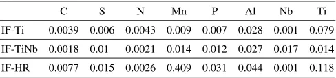
Table 1 Chemical composition of steel studied (in mass%).
C S N Mn P Al Nb Ti
IF-Ti 0.0039 0.006 0.0043 0.009 0.007 0.028 0.001 0.079 IF-TiNb 0.0018 0.01 0.0021 0.014 0.012 0.027 0.017 0.014 IF-HR 0.0077 0.015 0.0026 0.409 0.031 0.044 0.001 0.118
(a)
(b)
(c)
0 0.01 0.02 0.03
773 973 1173 1373 1573
Phase Fraction (%)
Temeprature, T / K
NbC TiN Ti(C,N) STi MnS
IF-Ti
0 0.01 0.02 0.03
773 973 1173 1373 1573
Phase Fraction (%)
Temeprature, T / K
NbC TiN Ti4C2S2 MnS
IF-TiNb
0 0.01 0.02 0.03 0.04 0.05 0.06
773 973 1173 1373 1573
Phase Fraction (%)
Temeprature, T / K
Ti(C,N) TiN (Ti,Nb)(C,N) Ti4C2S2 MnS
IF-HR
[image:2.595.47.291.84.141.2]steels studied. Results for IF-Ti steels indicate that C is tied up as (Ti,Nb)(C,N) and NbC. Bearing in mind the thermo-mechanical processing route followed, these results are consistent with the idea reported by De Ardo and co-workers18) that precipitates containing Nb can only be observed (in Ti and Nb IF steels) in the following conditions: (i) as casted, produced by continuous casting, (ii) reheated below 1273 K and (iii) thermomechanical processing (TMP) below 1273 K. The amount of such precipitates in IF-Ti steel is significantly lower than in IF-TiNb steel (Fig. 1(a) vs. Fig. 1(b)) because of the total Nb.
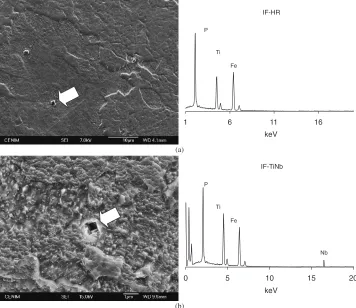
Figure 2(a) shows the SEM micrographs in IF-Ti steel, confirming the presence of very fine Ti(C,N) precipitates. Their small size may affect the progress of recrystallization process during annealing, since these particles can act as pinning points that impede the movement of growing grains. Besides, the precipitation temperature of these particles suggests that recrystallization and precipitation could be coupled processes, i.e. the precipitates are more prone to form in the sub-grain boundaries, and hence will delay or even impede the formation of recrystallize grain by sub-grain rotation or continuous recrystallization mechanism.
In the Nb added IF steels stabilization of C is largely independent of the Mn and S contents; while in the Ti-containing steels the stabilization of C depends upon the amounts of Mn and S present.19)In Ti-Nb stabilized IF steel, C is principally removed from solid solution by the formation of Ti4C2S2, shown in Fig. 2(b). The existence of these sulfur
compounds indicates that the reheating temperature of 1453 K in the steel has not been high enough to dissolve
before the roughing stage during processing. These precip-itates remove carbon from solid solution which promotes the deep drawing properties of the material through the forma-tion of a -fibre texture. However, the formation of these compounds avoid the formation of other precipitates that tied up phosphorus more effectively such as FeTiP, which has a detrimental effect on deep drawing properties by the presence of free P.20) It is important to note here that P is largely responsible for the hardness level of the steel that makes the steel competitive as car body panel material.21–23)
On the other hand, precipitation of (Ti,Nb)C is not predicted by calculations in IF-TiNb steel. In addition, Fig. 3 shows the distribution of Nb among the phases present in IF-TiNb steel for a certain temperature. It is clear that most of the Nb is tied up as NbC and only less than 20% of total Nb in the steel remind in ferrite. This result could lead to an improved cold work embritlement (CWE) performance of this steel as compared with similar steels reported in literature, where studies on stabilization of IF steels contain-ing (Ti+Nb) have shown that, dependcontain-ing upon the Ti level, as much as 67% of the total Nb may remain in solid solution.24) This solute Nb has been shown to segregate to grain and sub-grain boundaries thereby improving the CWE otherwise caused by P segregation at the same sites.20)
As indicated by Fig. 1(c), precipitation behavior of IF-HR steel is quite different and much more complex than that of IF-Ti and IF-TiNb steels. This can be attributed mainly to the amount of Ti,C. Likewise, as calculations indicate, P will remain in solid solution in IF-HR steel and thus will also result in solid solution strengthening. Figure 4 shows the (a)
(b)
IF-Ti
0
keV CN
Ti Fe
Ti
Fe
Fe
IF-Ti1-2
0 2
keV
Ti
Ti
Ti Fe
Fe Fe S
4 6
4 6
2
[image:3.595.122.477.73.376.2]amount of P and Ti in the matrix (ferrite) for the three steels studied. It is clear that, according with calculations, the whole amount of P and a significant amount of Ti remains in solid solution in the ferrite. However, it has been profusely reported in literature25,26) that in presence of Ti, P forms FeTiP phosphide which leads to the deterioration of both drawability and loss of strength. The FeTiP precipitates present in IF-HR steel (Fig. 5(a)), because of the Nb content, become Fe(Ti,Nb)P in Nb-rich steels (Fig. 5(b)), as has been previously reported in the literature.21,22) The presence of these precipitates depends mainly on the Ti and Nb content of steels. For this reason, the amount of these precipitates in
IF-TiNb steel is very small and almost negligible in the IF-Ti and IF-HR steels. The study of solubility products for the TiC and FeTiP done by Gladman23) shows that both are quite close, and hence those precipitates compete with each other. Thus FeTiP precipitate is more likely to be found in the IF-HS steel than in the IF-Ti steel because of the P content.
In summary, the precipitation events has been defined in IF-Ti, IF-TINb and in IF-HR steels with the help of MTDATA thermodynamic databank software. By means of ranking the precipitates by decreasing the free energy change during precipitation, the precipitation sequence can be summarized as follows: TiN, TixS, Ti4C2S2, TiC and FeTiP,
0 10 20 30 40 50 60 70 80 90 100
773 973 1173 1373 1573
Nb Fraction (%)
Temeprature, T / K
Austenite NbC Ferrite
Fig. 3 Distribution of Nb among the phases in IF-TiNb steel.
0 10 20 30 40 50 60 70 80 90 100
0 10 20 30 40 50 60 70 80 90 100
773 973 1173 1373 1573
P
Fraction (%)
T
i Fraction (%)
Temeprature, T / K
Ti in IF-Ti Ti in IF-TiNb Ti in IF-HR P in IF-Ti P in IF-TiNb P in IF-HR
Fig. 4 Distribution of Ti and P in solid solution in the matrix (ferrite).
(a)
(b)
IF-HR
1 11 16
keV Fe
Ti P
IF-TiNb
0 10 15 20
keV
Nb Fe
Ti P
5 6
[image:4.595.338.516.74.244.2] [image:4.595.77.263.74.245.2] [image:4.595.120.476.294.602.2]which agrees with thermodynamic studies reported about the precipitation sequence that occurs in these steels during solidification. After the formation of TiN, precipitation of sulfur compounds in the form of TiS, or more complex as the Ti4C2S2 is more likely to occur. The stability of the
precipitates depends on several parameters, including tem-perature and composition of steels.
3.2 Crystallographic orientation analysis
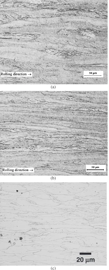
The deformed microstructures were composed of ferrite grains elongated along the rolling direction, some of which contained in-grain shear bands. Examples of these warm rolled microstructures are presented in Fig. 6 at low magnification. Figure 6 shows the as-quenched microstruc-ture of the IF-Ti and IF-TiNb steels after warm rolling and reheating at 1023 K (samples quenched just after reaching at 1023 K). It can be clearly seen deformed elongated grains in the rolling direction. Deformation bands are also oriented about 45 to the rolling direction. These bands are of great
interest for potential nucleation sites for recrystallized grains. These microstructures are similar to those obtained after cold rolling, i.e. high level of deformation is stored in the microstructure. It can be seen that the percentage of grains containing shear bands, and its intensities, are higher in the IF-Ti steel. On the other hand, the amount of shear bands in IF-HR steel is lower, which is consistent with the inhibition of shear band formation at higher rolling temperatures by the addition of phosphorus.26)
Figure 7 shows the ’2¼45 section of the orientation distribution functions (ODFs) of warm-rolled IF steels, and it is clear that both theandfibres are well developed. The fibre runs fromf001gh110i tof111gh110i, with clustering of poles at f001gh110i and f112gh110i. The fibre runs
fromf111gh110itof111gh112iand is peaked atf111gh110i.
A slightly stronger texture is detected as increasing the microalloying content. Stronger f111gh112i andf111gh110i textures is developed in IF-TiNb and IF-HR steels.
The EBSD analysis shows clear differences with the as-deformed microstructure after cold rolling process. Figure 8 shows the presence of sub-grains inside the coarser deformed grains. A more in detail observation of these sub-grains (Fig. 8(b)) reveals an average size of 2mmin mean diameter. Likewise, Fig. 8(c) shows a misorientation map between neighboring grains, where sub-grain boundaries (those with misorientation lower than 10) are clearly seen, meanwhile the grain boundaries of deformed grains have a misorienta-tion higher than 40. The presence of sub-grains allows us to conclude that the steel has followed a dynamic recovery process during the warm-rolling process. After EBSD analy-sis the deformed grain types can be classified in four different groups (Table 2). As an example, Fig. 9 shows the type-2 grains present in IF-HR steel.
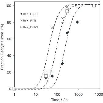
Figure 10 shows the evolution of the recrystallized fraction with holding time during isothermal treatment at 1023 K for the three steels studied. It is clearly seen an increasing delay on the kinetics of recrystallization as (a)
(b)
(c)
20 µm
Fig. 6 As-received optical microstructures of (a) IF-Ti, (b) IF-TiNb and (c) IF-HR steels.
(a) (b)
(c) (d)
3.2
φ 4
φ
ϕ1
4 φ
ϕ1
Fig. 7 2¼45sections of ODFs for (a) IF-Ti, (b) IF-TiNb, (c) IF-HR
[image:5.595.83.258.73.507.2] [image:5.595.306.547.73.293.2]microalloying element content increases. Thus, the IF-Ti steel presents the fastest recrystallization kinetics, followed by IF-TiNb steel and finally, the IF-HS steel. From the precipitation results presented in Fig. 1, we can conclude that
the differences in recrystallization kinetics are due to the differences in the amount of precipitates. Besides the higher amount of (Ti,Nb)(C,N), the main difference between IF-Ti and IF-HS steels lies mainly on the level of Ti4C2S2 and (e)
(a) (b)
(c) (d)
[image:6.595.121.477.70.487.2]Fig. 8 (a) Presence of sub-grains, (b) sub-grain sizes, (c) sub-grain boundaries, (d) misorientation histogram in the as-quenched microstructure of IF-HR steel. Legend of colour code for 8(a) is presented in (e).
Table 2 Deformed grains classification.
Type 1 Type 2 Type 3 Type 4
ND//<111> and
RD//<112> ∼ <110>
ND//<111> ∼ <335>
and RD//<110>
Around
{112}<110>
Around
{001}<110> ND
RD
ND
RD RD
ND
[image:6.595.142.455.548.714.2]FeTiP compounds. Therefore, the latter two should be responsible for the slower kinetics in IF-HS steel, not the Ti(C,N) precipitates more abundant in IF-Ti as compared with IF-TiNb steels. It is also well established that the presence of microalloying elements in solid solution may retard the recrystallization by solute drag phenomena.27)In this sense, because of the largest concentrations, IF-HS steel is more prone to present the most sluggish recrystallization
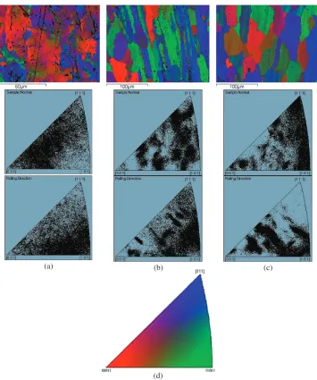
kinetics. The delay in recrystallization kinetics shown by IF-TiNb steel might be due to the combined effect of the precipitates MC-type (such as C0.88Nb) and Fe(Ti+Nb)P precipitates, and to a lesser extent, by solute drag phenomena. Finally, Fig. 11 shows the evolution of microtexture during recrystallization in IF-Ti steel. The deformed state (Fig. 11(a)) is a mixture of Type 2 and 3 grains, and the recrystallized grains has a strong texture with ND==h111i (Fig. 11(c)).
On the other hand, Fig. 12 shows the fully recrystallized microstructures of IF-Ti and IF-TiNb steels. It is clearly seen that the coarser final grain size of IF-Ti steel (39mm in average diameter) as compare with IF-TiNb steel (31mm average diameter). IF-HR presents the finer recrystallized grain size with a value of 21mm.
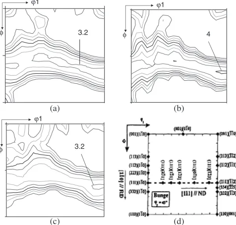
Figure 13 shows the recrystallization textures obtained after annealing at 1023 K. The final recrystallization textures developed in the three steels are quite similar in nature. They
show a prominent -fiber but maximums is not clearly
centered on f111gh112i. Likewise, the texture is decidedly sharper in both IF-Ti and IF-TiNb steels (containing less P) as compared with IF-HR steel, which also possesses a higher value of 4 as compared to 3.2 for IF-HR steel. The higher density of FeTiP precipitates in IF-HR steel appears to produce a less intense {111} texture. Besides, as it was above mentioned, the higher amount of P will decrease the amount of Ti in solid solution in the ferrite which will affect the averager-value. Excess Ti is necessary for attaining a better r-value.28)This is consistent with ther-values measured and listed in Table 3.
3.3 Recrystallization mechanism
In the following paragraphs the mechanism of recrystal-lization will be described. Previous works reported that deformation bands are noticeable features in the micro-structure of the present warm worked IF steel. Their directions to the rolling direction of 35 are independent of strain, temperature and initial grain orientations and are very similar to the banded structures reported in Al alloys.29) Likewise, it was observed that a decrease in recrystallization kinetics as compared with cold-rolled IF steels due to thermally activated processes such as dislocation cross slip and climb occur at a greater rate during warm rolling, and thus lower the overall dislocation density.30)
Meanwhile the recrystallization of the warm-rolled low carbon steel occurred mainly from deformed f100gh110i oriented grains (low energy nucleation), the main nucleation sites in the warm-rolled IF steels were the deformed {111} grains (high energy nucleation).31) The low stored energy nucleation occurs typically by the migration of a ‘bulge’ in an existing grain boundary from low energy grain into a high energy grain. It is easy to envisage site saturation occurring in a low stored energy material, when nucleation involves the bulging of existing grain boundaries, than when a subgrain growth or coalescence mechanism is operating.
(a)
(b)
Fig. 9 (a) Type 2 grains present in IF-HR steel. (b) Legend of colour code of 9(a).
0 20 40 60 80 100
1 1000 10000
Fraction Recrystallized (%)
Time, t / s ReX_IF-HR
ReX_IF-Ti
ReX_IF-TiNb
[image:7.595.77.260.73.412.2]10 100
Fig. 10 Hardness and recrystallized volume fraction evolution with time for isothermal holding at 1023 K.
Table 3 Measured averager-values.
IF-Ti IF-TiNb IF-HR
[image:7.595.310.544.86.112.2] [image:7.595.83.251.471.639.2]On the other hand, recrystallization nuclei in IF steels form preferentially within grains containing shear bands, probably because of the higher stored energies of these grains.32)The presence of shear bands of moderate intensity in warm-rolled IF steels, which tended to be insensitive to rolling temper-ature, where reported in literature.33) The development of shear bands was insensitive to the presence of microalloying precipitation, but shear band formation is inhibited at higher rolling temperatures by the addition of phosphorus.32)This is consistent with microstructures shown in Fig. 6, where shear bands are more abundant in IF-Ti and IF-TiNb steels than in IF-HR steel.
As to why low stored nucleation occurs, which is not the dominant mechanism in warm-rolled IF steels, it is due to the strain induced precipitation that occurs after some conditions of warm working of IF steel, which also is responsible of the retardation of recrystallization in warm-rolled material as compared with cold-rolled material.29)Senumaet al.34)have published results suggesting that the presence of Ti-precip-itates prevents bulging. Therefore, the continuous
recrystal-lization could be the controlling recrystalrecrystal-lization mechanism in IF warm-rolled steels.
Continuous recrystallization is referred as a mechanism in which a physical nucleus is not formed but rotations of two neighboring sub-grains coalesce in a new grain. If the recrystallization mechanism follows a sub-grain rotation or continuous recrystallization process, the texture of the new grain should not be very different than the previous deformed grain. However, if the predominant recrystallization mech-anism is by grain-boundary nucleation, the texture of the new grain could be very different than the one of previous deformed grain.
These are consistent with the experimental results obtained for IF-Ti, IF-TiNb and IF-HR steels (Fig. 14), and it allows us to conclude that grain-boundary nucleation could be the responsible recrystallization mechanism in IF-HR steel, meanwhile continuous recrystallization of grains nucleated in the shear bands is the responsible mechanism for IF-Ti and IF-TiNb steels. The micrographs in Fig. 11 show the evolution of the microstructure of the IF-Ti steel during the
(a) (b) (c)
[image:8.595.121.476.68.493.2](d)
isothermal annealing at 1023 K. The recrystallized grains nucleate first into certain deformed grains, while others do not exhibit any signs of recrystallization. The growth of these firstly recrystallized grains seems to be restricted to the same deformed grains where they nucleated. At later stages, the recrystallization affects all the initial deformed microstruc-ture. This picture is similar to those observed in IF-TiNb steel. In those steels, it was observed that the {111} grains do not have significant number advantage over ‘‘other’’ orienta-tions but are systematically more numerous than those belonging to {110} or {100} components. For this same sample, the number of the {111} grains remains almost constant, while the {100} and {110} grains decrease continuously in number during recrystallization.
4. Conclusions
Precipitates such as TiC and Ti4C2S2 in IF-Ti steel,
(Ti, Nb) (C, N) and Fe(Ti+Nb)P in IF-TiNb steel, and FeTiP in IF-HR steel have been observed.
It is clearly seen an increasing delay on the kinetics of recrystallization as microalloying content increases, probably as a result of solute drag phenomena. Thus, the steel with faster recrystallization kinetics is the IF-Ti steel, followed by IF-TiNb and finally, the IF-HR steel.
The presence of sub-grains in the microstructure as compared with cold-rolled steels indicates the existence of dynamic recovery processes during warm rolling of deep-drawing IF and IFHS steels. The sub-grains found in IF-HR steel are 2mmin size.
Grain-boundary nucleation could be the responsible recrystallization mechanism in IF-HR steel, meanwhile continuous recrystallization of grains nucleated in the shear bands is the responsible mechanism for IF-Ti and IF-TiNb steels.
The observed deformed grains in Ti-IF, TiNb and IF-HR steels can be classified into four distinct groups: Type 1
(ND==h111i and RD==h112i), Type 2 (ND==h111i and
RD==h110i), Type 3 (Around (112)h110i) and Type 4
(Around (001)h110i).
The most important alloying element in IFHS steels, which distinguishes this grade from the IF grade, is P, which is added intentionally for solid solution strengthening. A major problem with these steels is the formation of FeTiP which degrades the {111} texture in three different ways: These precipitates take out a substantial amount of stabilizing element Ti from the steel, leaving behind much less Ti in the matrix to combine with the interstitial elements. Secondly, removal of P atoms from the matrix will result in a material of poorer strength. And finally, FeTiP particles, often present along the grain boundaries, can produce Zener drag and retard the growth of favorable recrystallized grains, giving rise to a poor texture.
(a)
(b)
(c)
[image:9.595.83.257.70.519.2]40
µ
m
Fig. 12 Full recrystallized microstructures in (a) IF-Ti, (b) IF-TiNb and (c) IF-HR steels.
(a) (b)
(c) (d)
3.2 φ
ϕ1
4 φ
ϕ1
3.2 φ
[image:9.595.312.550.77.304.2]ϕ1
Fig. 13 2¼45sections of ODFs for (a) IF-Ti, (b) IF-TiNb, (c) IF-HR
Acknowledgements
The authors acknowledge the economical support of European Commission through the RFCS Programme (RFS-PR-03136) and the Spanish Ministerio de Ciencia e Innovacio´n through ENE2006-15170-C02-01 project. C. Capdevila Acknowledge the Spanish Ministerio de Educa-cio´n, Cultura y Deportes for economic support through the ‘‘Salvador de Madariaga’’ Program (PR2006-0045).
REFERENCES
1) T. Abe, T. Suzuki and S. Okada: Tetsu-to-Hagane´69(1983) S1415. 2) W. B. Hutchinson: Int. Met. Rev.29(1984) 25–42.
3) W. B. Hutchinson and K. Ushioda: Scan. J. Metall.13(1984) 269–275. 4) W. B. Hutchinson: Mat. Sci. Forum157–162(1994) 1917–1928. 5) K. Ushioda, W. B. Hutchinson and U. von Schlippenbach: Mater. Sci.
Technol.2(1986) 807–815.
6) K. Ushioda, T. Suzuki, H. Asano and M. Tezuka: 37th MWSp Conf. Proc., ed by C. E. Slater, (Iron and Steel Society, 1996) pp. 987–905. 7) H. Inagaki: ISIJ Int.34(1994) 313–321.
8) T. Funu, K. Marthinsen and E. Nes: Mater. Sci. Technol.6(1990) 1093–1102.
9) J. C. Herman, P. Cantinieaux and J. M. Langlais: Steel World2(1992) 48.
10) P. Messien: La Revue de Me´tallurgieCIT(1991) 433–442. 11) S. Hashimoto: Kobelco Tech. Rev.8(1990) 35.
12) L. Kestens, I. Gutierrez, J. L. Bocos, J. Zaitegui, V. Cascioli, P. E. Di Nuncio and R. Großterlinden:Texture Control in cold-rolled steel sheets for an optimized anisotropy, (European Commission, Brussels, 1999) p. 117.
13) T. Iung, G. Lanoo, C. Garcia de Andre´s and I. Salvatori:Metallurgical aspects of the compact reheating treatment of hot-rolled steels before coiling, (European Commission, Brussels, 2003) p. 28.
14) T. De Cock, JP Ferrer, C. Capdevila, F. G. Caballero, V. Lopez and C. Garcia de Andre´s: Scr. Mater.55(2006) 441–443.
15) H. J. Bunge:Texture Analysis in Materials Science—Mathematical Methods, (Butterworths, London, 1982) p. 1.
16) Metallurgical and Thermochemical Databank: http://www.npl.co.uk/
advanced-materials/measurement-techniques/modelling/mtdata, (Na-tional Physical Laboratory, Teddington, 1996).
17) M. Hua, C. I. Garcia and A. J. De Ardo: Scr. Metall. Mater.28(1993) 973–978.
18) H. Kang, C. I. Garcia, K. Chin and A. J. Deardo: ISIJ Int.47(2007) 486–492.
19) R. K. Ray and P. Gosh: 2nd Int. Conf. on Simulation and Processing of Steels SIMPRO 2008 (RDCIS, Ranchi, 2008) pp. 323–335.
20) P. Ghosh, R. K. Ray, B. Bhattacharya and S. Bhargava: Scr. Mater.55
(2006) 271–274.
21) W. J. Liu, S. Yue and J. J. Jonas: Metall. Trans. A20(1989) 1907– 1915.
22) B. C. De Cooman and A. De Vyt: Int. Forum for the Properties and Application of IF Steels-IF STEELS 2003, (ISIJ, Tokyo, 2003) pp. 249– 255.
23) T. Gladman:Physical Metallurgy of Microalloyed Steels, (Springer, Berlin, 1977) p. 1.
24) P. Ghosh, B. Bhattacharya and R. K. Ray: Scr. Mater.56(2007) 657– 660.
25) W. J. Liu and J. J. Jonas: ISIJ Int.30(1990) 985–990.
26) D. Liu, A. O. Humphreys, M. R. Toroghinezhad and J. J. Jonas: ISIJ Int.
42(2002) 751–758.
27) C. Capdevila, T. De Cock, C. Garcia-Mateo, F. G. Caballero and C. G. de Andres: Mater. Sci. Forum500–501(2005) 803–810.
28) S. H. Han, H. J. Kang and J. H. Chung: Proc. Int. Forum for the Properties and Application of IF Steels-IF STEELS 2000, (The Iron and Steel Society, Warrendale, PA, 2000) pp. 157–163.
29) G. H. Akbari, C. M. Sellars and J. A. Whiteman: Acta Mater.45(1997) 5047–5058.
30) M. R. Barnett and L. Kestens: ISIJ Int.39(1999) 923–929. 31) J. J. Jonas: J. Mater. Process. Technol.117(2001) 293–299. 32) Y. Z. Liu, J. H. Sum, L. Y. Zhou, Y. G. Tu, F. Xing, Y. C. Guo and Q.
Tong: J. Mater. Proces. Technol.140(2003) 509–513. 33) M. R. Barnett and J. J. Jonas: ISIJ Int.39(1999) 856–873.
34) T. Senuma, H. Yada, R. Shimizu and J. Harase: Acta Metall. Mater.38
(1990) 2673–2681.
(a) (b)
(c)
{–8 7 8} <–1 16 –15>
{–9 16 –1} <5 2 –13>
[image:10.595.130.471.71.350.2]{1 2 –2} <22 –16 –5>