Design Concept and Applications of Fe
Mn
Si-Based Alloys
®
from Shape-Memory to Seismic Response Control
Takahiro Sawaguchi
1, Tadakatsu Maruyama
2, Hiroaki Otsuka
2,
Atsumichi Kushibe
3, Yasuhiko Inoue
3and Kaneaki Tsuzaki
1,41Microstructure Design Group, Structural Materials Unit, Research Center for Strategic Materials,
National Institute for Materials Science, Tsukuba 305-0047, Japan
2R&D Group, Awaji Materia Co., Ltd., Tokyo 101-0052, Japan
3Research and Development Institute, Takenaka Corporation, Inzai 270-1395, Japan
4Department of Mechanical Engineering, Faculty of Engineering, Kyushu University, Fukuoka 819-0395, Japan
FeMnSi-based alloys exhibit a shape-memory effect associated with deformation-induced£¼¾martensitic transformation and its reversion. The£¼¾martensitic transformation also enhances mechanical properties, such as strength, hardness, wear-resistance and low-cycle fatigue lives of the alloys. In this article, we review fundamental researches on transformation behavior, microstructural and crystallographic characteristics, and functional and mechanical properties of the FeMnSi-based alloys, and introduce various examples of their practical applications. A special emphasis is placed on their new application as architectural seismic dampers, which were developed based on a new
finding of the passive two-way martensitic transformations under cyclic tensile-compressive loading. [doi:10.2320/matertrans.MB201510]
(Received October 1, 2015; Accepted December 21, 2015; Published February 15, 2016)
Keywords: ferrous-manganese-silicon alloy, shape-memory alloy,¾-martensite, low-cycle fatigue, architectural seismic damper, connecting device
1. Introduction
FeMnSi-based alloys are known as low-cost ferrous
shape-memory alloys that are applicable to large size structural components. Since a shape-memory effect was
discovered in an Fe30Mn1Si alloy single crystal in 1982,1)
intensive researches and developments of the FeMnSi-based alloys have been made both in scientific and industrial aspects, leading to practical use of connecting devices for
pipes and rails.2) The shape-memory effect of the FeMn
Si-based alloys are associated with deformation-induced
martensitic transformation from £-austenite with a
face-centered cubic (FCC) structure to ¾-martensite with a
hexagonal close-packed (HCP) structure, and its reversion on subsequent heating.
It has also been reported that the deformation-induced
¾-martensite in FeMnSi-based alloys can make the reverse
transformation into the£-austenite by the counter-directional
deformation,3,4) and the reversible two-way martensitic
transformation under cyclic tensile-compressive loading
improves the low-cycle fatigue lives.5,6)Based on thefining,
the present authors’ industry-academic-government joint
research group developed a new FeMnSi-based alloy with outstanding low-cycle fatigue lives, and succeeded in applying the alloy as architectural seismic damping
compo-nents in a skyscraper.6) A remarkable characteristic of the
new seismic damper is its extraordinary durability to accumulated damages caused by long-period and prolonged ground motion and frequent afterquakes. It is paid much attention as a new application of the FeMnSi-based alloys that have been used for shape-memory connecting applica-tions for long time.
The present article is devoted to the FeMnSi-based
alloys as shape-memory and fatigue-resistant alloys. We describe crystallographic, microstructural, and thermodynam-ic characteristthermodynam-ics of the FeMnSi-based shape-memory
alloys in relation to their functional and mechanical proper-ties in Section 2, and introduce various application examples of the FeMnSi-based shape-memory connecting and strengthening components in Section 3. We then describe the design concept and properties of the new FeMnSi-based fatigue-resistant alloy and the architectural seismic damper made of it in sections 4 and 5, respectively.
2. Fundamental Studies on FeMnSi-Based Shape-Memory Alloys
2.1 Crystallographic and microstructural characteris-tics of£¼¾martensitic transformation
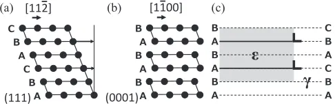
As shown in Fig. 1(a), (b),£¼¾transformation occurs by
shear displacement of close-packed atomic planes. The£- and
¾-crystals are in the so-called Shoji-Nishiyama orientation relationship: {111}£// {0001}¾, ©110ª£//©2110ª¾.7) This shear displacement can also be expressed as shown in
Fig. 1(c) where the ¾-martensite is consisted of stacking
faults on alternative {111} layers that are bounded by
a/6©112ªShockley partial dislocations staying at the growing
front of the¾-martensite.8)Reflecting such formation process,
{111} planes serve as habit planes for the¾-martensite that
exhibits thin plate morphology. There are twelve possible
shear systems consisted of four{111}planes and three©112ª
directions. The ¾-phase induced by cooling forms by the
$ % & $ % &
[112]
(111) (a)
$
%$
%$
%
[1100]
(0001) (b)
$ % $ % $ %
$ % & $ % &
(c)
γ
ε
Fig. 1 Atomic displacement and formation of partial dislocation-stacking fault units associated with£¼¾martensitic transformation.
Special Issue on New Aspects of Martensitic Transformations
[image:1.595.307.550.359.435.2]twelve shear systems with equal possibilities into a self-accommodation structure consisted of the four different
{111}habit-plane variants.9)Under uniaxial loading, on the
other hand, partial dislocations with high Schmid factors are
predominantly activated. Variants of the ¾-martensite are
selected depending on the crystallographic orientation, and their interactions affect the mechanical and functional properties of the alloys. The orientation dependence of the
shape memory property of FeMnSi alloys10) will be
described in Subsection 2.3.
The £/¾ interfaces do not move in the direction normal
to the interface, that is usually observed in thermoelastic martensitic transformations, such as those in Ti-Ni-based
shape-memory alloys. Instead, the¾-martensite grows in the
direction parallel to the£/¾interfaces, and thickening is made
through coalescence of neighboring thin ¾-plates.
Micro-structural observations revealed that the¾-martensite is likely
to showfine lamellar structures involving very thin remaining
£-layers and/or high probabilities of stacking faults.11,12)The
stacking-fault inside the ¾-martensite is a very thin £-plate
with a two atomic layer thickness. These microstructural characteristics may be associated with the distribution of nucleation sites and the growth of martensite crystals; the martensite growth is made by the motion of Shockley partial dislocations.
The generation of the partial dislocations is a critical
process for the£¼¾martensitic transformation. Up to now,
a number of nucleation mechanisms considering lattice defects such as pole dislocations,13)extended dislocations,14) stacking faults,15)as nucleation sites for the¾-martensite have been proposed and microstructural evidences for some of
them have also been reported.1416) Another important
microstructural component is stacking faults of the£-crystal.
Because the atomic arrangement of the stacking fault of the
£-crystal is equivalent to a thin ¾-crystal with two atomic
layer thickness, some investigators regard the stacking fault
as an embryo of the¾-martensite and discuss the effect of the
stacking fault energy on the formation process of the
¾-martensite and the shape-memory property.17,18) Recently, it
has become mainstream that considering the contribution
from the volume energy of the¾-martensite with two atomic
layer thickness, the stacking fault energy is calculated from
the Gibbs free energy difference between the £- and ¾
-phases.19)The calculated stacking fault energy is known to be
useful to predict the plasticity mechanisms of various high-Mn austenitic steels (See Subsection 2.3). Although these two approaches are opposite in terms of the cause-effect
relation, it is an important fact that the £-phases of the Fe
MnSi-based alloys contain substantially high probabilities of stacking faults.
2.2 Functions of elements
Manganese is the first necessary element in
FeMnSi-based alloys, and it has two roles with respect to the thermodynamic stability of the phases. First, manganese
stabilizes the£-austenite with an FCC structure that is a high
temperature phase of iron at room temperature. Second, even
under normal pressure manganese stabilizes the¾-phase with
an HCP structure, which is thermodynamically stable only under high pressure in the case of pure iron. Because the
thermodynamic equilibrium temperature between the £- and
¾-phases is in the vicinity of room temperature, that is too low
for atoms to diffuse, the¾-phase forms martensitically in the
alloy by undercooling or loading. The shape-memory
phe-nomenon is such that the deformed state where the
¾-martensite is induced as shown in Fig. 1(b) returns into the
original £-austenite represented in Fig. 1(a) through the
reverse transformation on heating; however, the shape recovery strain available in binary FeMn system alloys is
very small.20)To realize a recognizable shape-memory effect,
the second necessary element, silicon, should be added. Sato et al. reported for the first time that Fe-30Mn-1Si alloy single crystals exhibit a large shape recovery strain.1)It was followed by confirmation of the shape-memory effect in polycrystalline alloys, and optimum composition range was
also clarified.21) In the ternary FeMnSi system, optimum
concentration ranges are 28³33 mass% for Mn and 5³6
mass%for Si, respectively. The compositional conditions are
chosen to have £¼¾ martensitic transformation start, Ms,
temperatures in the vicinity of room temperature. Subse-quently, various compositions of FeMnSi-based shape-memory alloys were proposed by partially replacing Mn with
substitutional elements such as Cr, Ni, Cu, Al etc.2225)The
balance among the concentrations of the alloy components
is adjusted taking the Ms temperature of the £¼¾
transformation and the austenite stability against ¡A
marten-site into the consideration. It is also reported that small amount of interstitial elements, such as C and N, strongly
stabilizes the£-austenite and reduces Mn concentration when
they are solutionized in the parent£-phase.26,27)At the same
time, the additives are also beneficial for elevating industrial values of the material, such as corrosion-resistance, strength, formability, and low production cost. To predict the phase transformation behavior and to design shape-memory property, the optimum concentrations of the alloy compo-nents can be calculated with various equations for the Gibbs
free energy difference between the£- and¾-phases,2831)and
various empirical equations for Mstemperature of the£¼¾
transformation.32,33)
On the other hand, the roles of silicon are diversified and complicated. Silicon hardens the parent matrix to suppress
the dislocation gliding, while it promotes the £¼¾
martensitic transformation through lowering the stacking
fault energy.34,35) Magnetism of the alloy is also important
factor affecting the phase transformation.3638)The£-phase in
the FeMnSi-based alloys undergoes paramagnetic to anti-ferromagnetic transition, and the anti-anti-ferromagnetic ordering
of electron spins is reported to stabilize the £-austenite and
suppress its transformation into the ¾-martensite. Silicon is
known to lower the magnetic transition temperature of the FeMnSi-based alloys to subzero temperatures and thus
promote the £¼¾ martensitic transformation at room
temperature. It is also pointed out that silicon possibly produces any short range ordering of the atoms to improve
the reversibility of the reverse ¾¼£ martensitic
trans-formation.39)Another factor elevating the reversibility of the
reverse transformation is the improved coherency between
the £- and ¾-lattices with silicon addition.40) Each role of
silicon has a composite effect of them. Interestingly, in spite of such complicated factors, optimum additive amount of Si to obtain the best shape recovery strain is always 5 to
6 mass% even in different alloy systems, such as
Fe-14Mn-12Cr-4Ni-Si41)and Fe-17Mn-0.3C-Si.42)
2.3 Functional and mechanical properties
One of the most important properties of the shape-memory alloys is the shape recovery strain. In connecting applica-tions, a larger shape recovery strain is required to overcome the gap between the contacting objects. The FeMnSi alloy
single crystal exhibits a shape recovery strain of 8% when
tensile deformation occurs in the ©414ª direction, while the
recovery strain in the©001ªdirection is only one-fifth of the
former, due to the orientation dependence of the £¼¾
martensitic transformation described in Subsection 2.1.10)
Polycrystalline FeMnSi-based alloys generally show much
smaller shape recovery strains of more or less 2% in
as-annealed conditions, due to geometric constraint between
grains.43)It is known that pre-straining followed by annealing
improves the shape recovery strain.44) In particular, when
straining and shape recovery heating are repeated, the shape recovery strain gradually increases, which is called as the
training treatment.45)With the training treatment, the shape
recovery strains of FeMnSi-based alloys increases to above
4%. Single hot rolling with or without post-rolling annealing
also have the similar effect with the training.46,47) In some
FeMnSi-based alloys, small amount of C or N is added to
produce their precipitates, such as NbC,4850) VN,51) VC,52)
Cr23C6,53)etc. with the finishing aging treatment to improve
the shape-memory property. Texture development54) and
grain boundary nature55)are also reported to affect the
shape-memory property. Particularly, in Ref. 55), a giant recovery
strain as large as 7.6%was obtained in an annealing twin-free
microstructure produced in an Fe-20.2Mn-5.6Si-8.9Cr-5.0Ni alloy by a casting-annealing process. Although the detailed mechanisms and validity of the wide variety of the
thermo-mechanical treatments still leave room for argument,56) the
microstructures created by these processes are commonly
aiming at promotion of the£¼¾martensitic transformation
on plastic loading and the crystallographic reversibility of the reverse transformation on subsequent heating.
The shape recovery stress is also an important parameter that determines the performance of the connecting and strengthening components. The mechanism for generating the
recovery stress is discussed in the literature,2,57) which can
be summarized as follows. On heating, the shape recovery contraction strain cancels thermal expansion of the objects and shape-memory devices themselves, and the reverse transformation continuing after contacting of the objects produces an elastic stress. On cooling, thermal shrinkage further increases the elastic strain, unless it reaches the plastic yielding stress or the critical stress for inducing martensitic
transformation at each temperature.57) The larger the initial
gap between the connecting objects is, the lower the recovery stress is.2) Therefore, sufficiently high critical stresses not only for the plastic deformation of austenite but also for the martensitic transformation at all the temperatures during the constraint heating-cooling process are required to obtain a high final stress to connect or strengthen the object(s).
The £¼¾ martensitic transformation in the FeMn
Si-based alloys is generally considered to be non-thermoelastic-type and not to show superelasticity. However, depending on chemical composition and deformation conditions, the Fe MnSi-based alloys show a relatively large and non-linear spring-back on unloading that is addressed as a partial
pseudo-elasticity.58,59) Especially, the recovery strain on
unloading reaches the maximum value in the vicinity of the
reverse martensitic transformation finish, Af, temperature,
which suggests that the non-linear spring-back phenomenon during the unloading is a kind of transformation
pseudo-elasticity.60) The recovery ratio by this pseudo-elasticity is
however small due to ever coexisting irreversible plasticity, and no complete superelasticity is available in the FeMnSi-based alloys. The concomitant partial transformation pseudo-elasticity and dislocation activity are attributed to so-called a
“semi-thermoelastic”microstructural features.61)
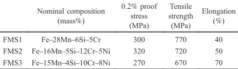
Because the FeMnSi-based shape-memory alloy prod-ucts are used as a part of structures after the shape-memory effect has been expressed, the strength and environmental resistance of FeMnSi-based alloys is also a property suitable to these applications. Table 1 shows nominal compositions and mechanical properties of three commer-cially available FeMnSi-based alloys. FMS1 has out-standing shape-memory characteristics and weather resist-ance and the amount of expensive chromium added is kept to a minimum, so its cost performance is high. This alloy is used in most of the applications of FeMnSi-based shape-memory alloys introduced in Section 3. FMS2 is a stainless-steel-type shape-memory alloy, or is sometimes called as a shape-memory stainless-steel. The chemical composition of
FMS2 was designed referring to the FeCrNi stainless-steel
to improve its corrosion resistance. FMS3 is the new damping alloy for seismic response control, which will be introduced in Sections 4 and 5. The mechanical properties of the FeMnSi-based alloys can be understood, as done in
high-Mn austenitic steels.62) The high-Mn steels are
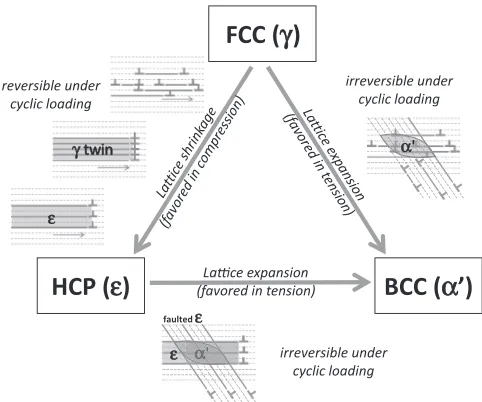
wear-resistant steels invented in 19th century, and are still useful today as, for example, rail crossings, jaw crasher, etc. In a broad sense, ferrous alloys and steels containing high concentration of Mn, such as Ni-free stainless steels, non-magnetic steels, and cryogenic steels, are also called as high-Mn steels in these days. A common feature of the high-high-Mn steels is appearance of diversified plasticity mechanisms, which are schematically illustrated in Fig. 2, in relation to the phase stability of three basic crystal structures of iron and steels. Between FCC and HCP structures, plastic deformation is made by various modes of extended dislocation gliding (a),
mechanical £-twinning (b), and £¼¾ martensitic
trans-Table 1 Nominal compositions and mechanical properties of FeMn Si-based alloys. FMS1 and FMS2 are shape-memory alloys (FMS2 is stainless-steel-type); FMS3 is fatigue-resistant seismic damping alloy.
Nominal composition (mass%)
0.2%proof stress (MPa)
Tensile strength (MPa)
Elongation (%)
FMS1 Fe28Mn6Si5Cr 300 770 40
FMS2 Fe16Mn5Si12Cr5Ni 320 720 50
[image:3.595.306.549.106.177.2]formation (c), as a result of expansion of stacking faults and their regular or irregular overlapping depending on relative £/¾stability.63)The stacking fault energy is also an important variable to determine the plasticity mechanisms.
On the other hand, there is another type of martensite, that
is, ¡A-phase with a BCC (or BCT depending on chemical
composition). Usually, the ¡A-phase is rather more popular
than the¾-phase as a martensite in steels. The¡A-martensite is
reported to form at the intersections of¾-martensite plates and
slip bands (d), (e). The martensites and twins are known to improve the strength-elongation balance of the steels, which is known as transformation-induced plasticity (TRIP) effect
and twinning-induced plasticity (TWIP) effect.64) In this
aspect, FeMnSi-based alloys can also be regarded as a kind
of high-Mn steels, where the deformation-induce¾-martensite
brings about sharp strain hardening, high strength, and good enough ductility.
3. Various Examples of Applications of FeMn Si-Based Shape-Memory Alloys
3.1 Early application examples
The basic research for the practical realization of FeMn Si-based polycrystalline shape-memory alloys and the development of applications began in around 1984. Initially, applications as replacements for Ti-Ni alloys and applications used for sales promotion of the utilization of new materials known as shape-memory alloys were numerous. A classic
example is lock rings for bicycle frame pipes (Fig. 3).65)
Aluminium, titanium, and carbon pipes, which are difficult to connect, are employed in advanced bicycle frames for sports, and internal grooves are cut into the end sections of these pipes after C-shaped rings made of FeMnSi-based shape-memory alloys to which shape-memory treatment has been applied to widen them outwards are set, lugs (made of lost-wax-cast aluminium) are inserted and heated to join the two parts (adhesives are also used). However, FeMnSi-based shape-memory alloys are not essential for such applications and, because the quantities used were also small, development then moved on into unique applications that were impossible without these alloys.
3.2 Powder blowing nozzle protection pipes and joints for curved pipe roof construction methods
Ti-Ni alloys, which are known as representative shape-memory alloys have numerous applications (representative example: water mixing taps) in which their property of repeating shape changes through heating and cooling is utilized and applications in which superelasticity effects are used (orthodontic wires, etc.), while FeMnSi-based shape-memory alloys are suitable for applications in which they are used in structures after their shape-memory effect has been exercised once, such as the connection of two or more members. Moreover, because they are iron-based alloys, they can easily be used to create relatively large members, and
“fastening members for connecting relatively large members”
has come to be thought of as a suitable field for the
application of FeMnSi-based shape-memory alloys.
The earliest application developed in such afield was for
powder blowing nozzle protection pipes (realized in around 1991). Powder blowing nozzles are nozzles used to blow coal from the furnace bottom of a converter furnace into molten iron in the furnace. Because heat resistance and wear resistance are required, ceramic pipes (with diameters of several tens of millimetres) are used in the central parts of pipes through which powders of coal pass, but in order to hold and protect these ceramic pipes, the outsides of the pipes are covered with FeMnSi-based shape-memory alloy pipes with an interposed buffer layer of copper and the two are integrated using shape recovery. This application is, as it were, an application in which materials of different types,
ceramic and metal, are joined.66) Because the length of the
nozzle is 1 metre or greater, it is a relatively large-scale application. A similar example of application is bulk superconductors for reinforcement of shape-memory alloy pipes. These are relatively small and cylindrical in shape, but it has been reported that, by reinforcing the outside of a bulk superconductor into which ceramic powder has been baked in with a shape-memory alloy ring, not only can breakage and
Pipe
Shape-memory alloy ring Lug
Shape-memory alloy ring
Pipe Pipe
Lug
Before heaƟng Heated
Shape-memory alloy ring
Lug
Fig. 3 Fe28Mn6Si5Cr shape-memory alloy lock ring for bicycle frame pipe.
FCC (
γγ
)
HCP (
ε
)
BCC (
α
’)
α ε
γ twin
Laƫce expansion (favored in tension) reversible under
cyclic loading
irreversible under cyclic loading
α' irreversible under
cyclic loading
ε ααααααααααααα faulted ε
[image:4.595.48.289.438.639.2] [image:4.595.97.494.691.771.2]cracking of easily-damaged bulk superconductors be pre-vented, but the performance of the bulk superconductor can
also be improved through reinforcement67)(Fig. 4).
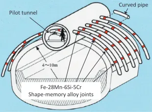
Moreover, in 2003, pipe joints made of Fe28Mn6Si5Cr shape-memory alloy produced by centrifugal casting were employed in the construction of the Wakunami Tunnel in Kanazawa, Japan. This was a new construction method in which a rib-shaped row of wide steel pipes were configured sideways starting from a small base space (pilot tunnel) in the earth. It was confirmed that, in a construction method in which short curved pipes with an external diameter of approximately 300 millimetres and a length of several metres were inserted while being connected in a narrow space in the earth and, after a curved pipe row (rib-shaped roof ) like that
shown in Fig. 5 was configured in the earth, the area below
the roof was excavated to form a tunnel, shape-memory alloy pipe joints were outstanding as pipe joints for efficiently
connecting the curved pipes.68,69)However, this method was
only employed once, primarily because of cost issues.
3.3 Crane rail joint plates
Crane rail joint plates (Fig. 6)70) have been used and
caused no problems in the ten years they have been in use. A total of approximately 3000 plates (30 tons of material) are already in use, and the number of plates employed is still increasing. Moreover, not only do these plates make it possible to connect rails in a short amount of time, but connected left and right rails can be pulled together by the shape-memory effect, so even if heavy articles pass repeatedly over the rails, no gaps appear between the rails, so the amount of work required for rail maintenance can also be greatly reduced.
Ironworks cranes have to work not only during plant operation, but also during regular renovations of the plant. These joint plates sufficiently meet the needs of maintenance of the rails themselves, frequency of rail replacement, and keeping replacement work time to a minimum. Moreover, a nine-year outdoor exposure test of a set of joint plates made of the Fe28Mn6Si5Cr (FMS1) alloy connecting rails confirmed that no corrosion occurred, including galvanic corrosion, so it is thought that application for the use of these plates not only in plants but also in rails in outdoor facilities will move forward. The analysis on the rust structure using electron energy loss spectroscopy (EELS) and transmission electron microscopy (TEM) revealed that the protective Cr-Si rich layer is responsible for the high corrosion resistance.71)
3.4 Prestressed concrete and concrete repair
Concrete prestressed using FeMnSi-based shape-mem-ory alloys is another example of an application being considered. In order to strengthen a concrete structure by compressive force, shape-memory alloy components are pre-tensile deformed, embedded in the concrete and heated. There have been proposed several applications for concrete structures with FeMnSi-based shape-memory alloy rods, fibres, and machined chips as reinforcements.7275)Moreover, there are also examples of application to repair of damaged concrete using the shape recovery contraction stress produced in FeMnSi-based shape-memory alloy rods that are
pre-tensile deformed and subjected to the on-site-heating.76)Such
applications of FeMnSi-based alloys in civil engineering
are also reviewed in.77)
4. Development of Fatigue-Resistant FeMnSi-Based Alloys
4.1 Design concept
In this and next sections, we will introduce FeMnSi-based alloys characterized by outstanding fatigue resistance and architectural seismic dampers, which are an application
for these alloys. This is a newfield, in which the mechanical
characteristics of FeMnSi-based alloys, rather than the shape-memory effect, are utilized. This also represents the proposal of a new way of thinking directed at the develop-ment of materials to improve low-cycle fatigue life. A series
of the related researches was triggered by finding of an
interesting microstructural evolution in an FeMnSi-based
shape-memory alloy under alternative tensile-compressive loadings.3,4)
Shape-memory alloy ring
YBCO bulk superconductor Resin coat
Fig. 4 Bulk superconductor reinforced by Fe28Mn6Si5Cr shape-memory alloy ring with resin coating for waterproofing (right) and without resin coating (left).
Pilot tunnel
Fe-28Mn-6Si-5Cr Shape-memory alloy joints
Curved pipe
Fig. 5 Schematic drawing of tunnel construction method using curved pipes. The red sections in thefigure are centrifugally cast Fe28Mn6Si 5Cr shape-memory alloy joints.
Before heaƟng
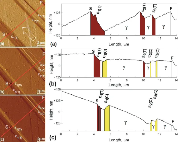
[image:5.595.334.520.70.185.2] [image:5.595.91.246.72.181.2] [image:5.595.92.247.238.352.2]Figure 7 demonstrates atomic force microscopic images taken at an identical area on the pre-polished surface of an Fe28Mn6Si5Cr0.5NbC alloy subjected to stepwise
tensile-compressive deformation consisted of 3%tension (a),
subsequent compression to the zero net strain state (b), and
further compression to ¹3% (c).4) The tension-induced
¾-martensite with a dark banded contrast in (a) disappears by subsequent compression as shown in (b) and further
compression induces new ¾-martensite variant with a bright
contrast in (c). Assuming that the compression-induced
¾-martensite also reversely transforms into the £-austenite by
inversion of the loading direction from compression to tension, reversible microstructural changes are expected in the following cyclic deformation. It means that the reverse
transformation of the deformation-induced ¾-martensite is
possible not only by heating but also by counter-directional loading. The reverse transformation on heating
spontane-ously occurs when sufficient chemical driving force is
obtained, while that by inversion of loading direction is passively activated following dislocations conveyed by external force. Later, the unique deformation mechanism came out to improve low-cycle fatigue lives, leading to new design criteria of fatigue-resistant alloys. We also consider various plasticity mechanisms of high-Mn steels to establish the criteria.
Based on the finding of the beneficial effect of the
reversible two-way transformations between the £- and
¾-phases,3,4) the present authors analogized that the plasticity
mechanisms of high-Mn steels shown in Fig. 2, i.e., (a)
extended dislocation glide, (b) mechanical £-twinning, and
(c) £¼¾ martensitic transformation, may be commonly
durable to cyclic deformation, because all of these involve the Shockley partial-stacking fault unit as a microstructure component that can make the back-and-forth movement
under cyclic loading without cross-slip, as the ¾-martensite
does. To confirm this assumption, we investigated low-cycle fatigue properties of various high-Mn steels and found empirical laws to improve the low-cycle fatigue lives of the
FeMnSi-based alloys:5,6) i) balancing phase stability
between the £- and ¾-phases, ii) suppressing the induction
of ¡A-phase under loading, iii) adding Si of approximately
4 mass%.
4.2 Problems for mass-production
The development was made keeping in mind the mass-producibility of large members for use in buildings. Because of the large quantity of manganese included, the most popular shape-memory alloy, FMS1 in Table 1, has been made by the small induction melting furnaces. They are convenient for use in manufacturing test materials, but when mass-produced products are created using such furnaces, materials costs inevitably become high. Because shape-memory alloy products are generally compact and produced in limited quantities, the induction melting furnaces have been used even for actual production. However, in order to move forward with applications to large-scale structural members, it has become essential to produce large volumes of materials at larger scales inexpensively.
Meanwhile, in the production of stainless steel for practical use, electric arc furnaces are widely used. The melting of stainless steel in electric arc furnaces is performed as follows. First, scrap with iron as a principal component is molten in the electric arc furnace, after which the molten steel is received in a ladle. In the ladle, impurities are removed from the molten steel, while necessary alloy elements are added, and the alloy is made to solidify by tapping.
If an FeMnSi-based shape-memory alloy is to be
[image:6.595.143.457.72.321.2]order to prevent this, it is necessary to melt in the manganese raw material while maintaining the temperature of the molten steel using a special ladle provided with a heat-elevation mechanism called an LF (Ladle Furnace). Furthermore, because the vapour pressure of manganese is higher than that of the iron that is the principal component, the problem arises that, even if the manganese is molten successfully in the LF, it will vaporize earlier if the refinement operation is continued as-is.
In order to avoid this problem, the addition of manganese raw material in the LF must be performed immediately prior to tapping. In this situation, impurities in the manganese raw material are not removed and remain in the product, so raw material with a high degree of purity and few impurities must be used. Because this series of problems becomes more prominent the greater the amount of manganese being added is, generally, the upper limit for manganese content that can be molten in an electric arc furnace for stainless steel
production is considered to be around 15 mass%.
Because of these issues, the development of low-cost Fe MnSi-based shape-memory alloys for mass production in
which manganese content is kept to a low level of 15 mass%
or less has been known as a future issue since a relatively early stage and the concept of low-manganese-concentration
composition design has also been proposed.78) In design
guidelines for achieving low manganese concentration, the fact that added chromium and nickel to improve corrosion resistance and the addition of carbon for improving shape recovery by solid solution strengthening are also linked to reducing manganese quantity has been used. For instance, the stainless-steel-type shape-memory alloy Fe16Mn5Si
12Cr5Ni,79) which is the second commercialized
composi-tion shown in Table 1 (FMS2), has a low manganese content
of 16 mass% by weight. However, switching to electric arc
furnaces with high furnace volume has become possible only after demand matches production quantities.
4.3 Properties of fatigue-resistant FeMnSi-based alloy
Thus, the new fatigue-resistant alloy Fe15Mn4Si10Cr 8Ni, FMS3 in Table 1, for architectural seismic response
control was developed, based on both scientific and industrial
knowledge described in subsections 4.1 and 4.2, respectively. With the idea of achieving the mass production of large-scale damper products for employment in actual skyscrapers,
manganese concentration was kept 15 mass% by weight,
which allows for production in electric arc furnaces. On the basis of design guidelines (Subsection 4.1) for improving fatigue life, the blending ratios of manganese, chromium, and nickel have been adjusted so as to balance£/¾phase stability. Moreover, by comparison with stainless-steel-type SMA (FMS2), the nickel content is higher while the chromium
content (¡A phase formation suppression) and the silicon
concentration is slightly lower. Using an electric arc furnace for production with an authorized capacity of 10 tons, this
was the first FeMnSi-based alloy successfully
manufac-tured using the “electric arc furnace+LF” process. This
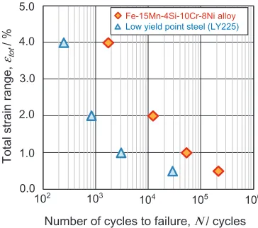
alloy has the advantage of a low-cycle fatigue life approximately ten times that of conventional low-yield-point steel (LY225), as shown in Fig. 8. The alloy also exhibits good mechanical properties as listed in Table 1.
5. New Application as Architectural Seismic Dampers
5.1 Overview of earthquake countermeasure technology
In recent years, the spread of seismic isolation and vibration control structures that protect buildings from earthquake damage has advanced rapidly. Figure 9 shows conceptual drawings comparing common earthquake resist-ant structures with seismic isolation structures and vibration control structures. Although conventional earthquake resist-ant structures allow damage to principal structural members (columns and beams) when major earthquakes occur, they are intended to prevent collapse and protect human lives. Meanwhile, in seismic isolation and vibration control structures, seismic isolation devices and seismic damping devices that absorb seismic energy are installed suitably in the building and reduce swaying of the building. These structure types are intended not only to protect human lives but also to reduce damage to principal structural members and protect property within the building.
Seismic isolation structures are a structure type in which isolators that break the connection between the building and the ground are installed in combination with dampers that absorb seismic energy. The isolators support the building and allow the building to move slowly when an earthquake occurs, while the dampers suppress swaying.
Vibration control structures employed in many skyscrapers are a structure type intended to preferentially absorb seismic energy in dampers when an earthquake occurs and to minimize damage to the principal structural members (columns and beams) by reducing swaying of the building. Representative types of seismic damping devices include steel dampers, in which the elastoplastic deformation of low-yield-point steel (steel with lower strength than that of ordinary architectural steel) is used, and viscous dampers and oil dampers, in which the viscous resistance of viscous bodies
or oil is used.80) In skyscrapers, in order to ensure the
redundancy and robustness of quake resistance performance, multiple damping devices are used considering the character-istics and suitable locations of each type.
5.2 Needs of countermeasures against period, long-duration seismic motion
Recently, from the standpoint of post-earthquake business continuity (Business Continuity Planning), the need for high-performance dampers with high durability that can continue to be used without replacement even after a disaster in order to greatly reduce recovery expenses and time has increased. Furthermore, society has also become aware of the importance of damage control measures against the long-period, long-duration seismic response of skyscrapers, which have larger amplitude and longer period of vibration than lower buildings, due to resonance of the skyscrapers with seismic ground motion in which long-period components are
predominant.81)
loads they can withstand being small because of low rigidity, high cost, and the like. Meanwhile, the low-yield-point steel dampers have outstanding cost performance, large load withstanding and high rigidity, so they have been most generally used and indispensable particularly for economical vibration control structure. However, in a case where insufficient durability due to metal fatigue is concerned, the conventional low-yield-point steel dampers
have been difficult to use in maintenance-free
counter-measure technologies for long-period, long-duration seismic motion.
With this background, in order to greatly improve the performance of steel dampers, we created a new metallic
seismic damper that can be used as the world’s first
countermeasure technology for long-period, long-duration seismic motion, using the fatigue-resistant Fe15Mn4Si 10Cr8Ni (FMS3) alloy with ten times the low-cycle fatigue life of conventional low-yield-point steel as the
energy-absorbing member.6)In order to acceptably utilize material
performance, various creative features have also been implemented in the structure of damper members.
5.3 FeMnSi-based alloy seismic dampers
Figure 10 shows the appearance of a seismic damper made of the FMS3 alloy and the inside FMS3 alloy panel (the energy-absorbing member). The damper is a shear panel type
seismic damper that exhibits a hysteresis damping effect due to elastoplastic deformation occurring between top and bottom of the alloy plate. Under a maximum envisioned
deformation angle of 1/25 rad, the damper can bear a load of
approximately 4,000 kN, which places it in the highest class of metallic dampers.
By making the end of the alloy panel R-shaped, the stress distribution produced in the panel is controlled and, at the same time, the reliability of the bolt joint between the stiffening plates required to transmit loads under high deformation is improved.
If the amount of shear deformation of the alloy panel exceeds a certain limit, buckling can occur. The occurrence of major buckling can bring about reduction in panel strength and early breakage due to strain concentration, preventing the inherent potential of the FMS3 alloy from being exhibited. Thus, mechanisms to prevent buckling of the alloy panel are essential in seismic dampers. In order to utilize the outstanding fatigue endurance of the FMS3 alloy, we developed a buckling stiffening system that continuously stiffens the entire surface of the deformation area with a two-ply stiffening plate and applied it to the FeMnSi-based alloy seismic damper.
5.4 Performance of FeMnSi-based alloy seismic damper
In order to confirm the deformation performance and fatigue resistance of the FMS3 alloy seismic dampers, we performed a dynamic load testing. Because of the load limiting of the force application actuator, the test sample was given a shape similar to that of the seismic damper designed with the height, width, and panel thickness of the movable portion of the FMS3 alloy panel reduced to half scale.
Figure 11 shows the force application system and the test sample for the dynamic load testing. The force application device used was a large dynamic actuator with a maximum load capacity in the 2,000 kN class. Shear deformation was applied to the test sample via horizontal displacement of a steel beam. Using this force application system, a progressive strain increase test and a low-cycle fatigue test at constant strain amplitudes were performed on the damper we developed.
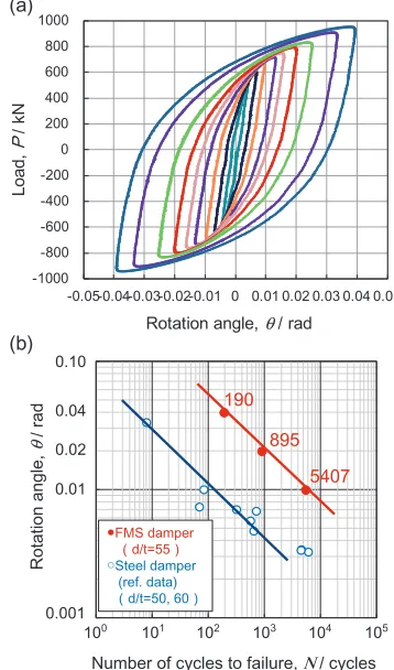
The test results obtained from the dynamic load testing are shown in Fig. 12. Figure 12(a) shows the relationship between the load and the deformation angle obtained by progressive strain increase test. In order to confirm the stable deformation performance under the wide range of deforma-tion required in seismic dampers, a progressive strain
increase test up to a deformation angle of 1/25 rad, a value
If an seismic isolation structure cannot be employed
There is no damage to the structure; damage is limited to the damping device section. However, furniture and the like may fall.
Maintains human safety, but allows damage to structure
Earthquake resistant structure
Seismic isolation structure
The safest structure; not only is the structure not damaged, but furniture does not fall and the safety of objects inside is ensured. Seismic isolation structures are optimal when conditions for using seismic isolation structures are all met.
Vibration control structure
Fig. 9 Conceptual drawings of earthquake resistant structure, seismic isolation structure, and vibration control structure.
1XPEHURIF\FOHVWRIDLOXUHΝF\FOHV
7RWDOVWUDLQUDQJH
εWRW
)H0Q6L&U1LDOOR\ /RZ\LHOGSRLQWVWHHO/<
[image:8.595.303.549.70.156.2]Fig. 8 Low-cycle fatigue properties of Fe15Mn4Si10Cr8Ni alloy.
[image:8.595.77.259.71.232.2] [image:8.595.50.290.270.418.2]assumed for an earthquake of maximum scale, was performed. Three cycles of a sinusoidal wave with a period
of five seconds were applied at each amplitude, assuming
resonance of the skyscraper with long-period seismic motion. No discontinuous load decreases due to buckling or failure were seen and the relationship between load and deformation angle was stable from small deformation angles to large deformation angles, so the hysteresis loop (the area within the loop represents the quantity of energy absorption) was also stable. In this way, the outstanding deformation performance and energy absorption performance of the alloy in seismic dampers were clarified.
In order to examine the fatigue endurance of the seismic dampers, strain-controlled low-cycle fatigue tests were performed at representative shear deformation angles of 1/100, 1/50, and 1/25 rad. A sinusoidal wave vibration with
a period of five seconds was also used in the tests. The
number of cycles at which the maximum load decreased by
10% from the maximum load was used as the fatigue life.
Figure 12(b) shows the results of low-cycle fatigue tests.
Values from the literature82,83) for steel-based shear panel
type dampers were also plotted in thefigure for comparison.
The widththickness ratio d/t (d: panel deformation site
height; t: panel thickness), which affects the fatigue
characteristics of shear panels, was made to be roughly equal for the comparison. The developed damper is found to have far superior fatigue life to existing steel dampers.
On the basis of the above, the outstanding deformation performance and outstanding durability in low-cycle fatigue regions of FeMnSi-based alloy seismic dampers were confirmed.
As shown in Fig. 13, in 2014, sixteen seismic dampers using Fe15Mn4Si10Cr8Ni (FMS3) alloy were installed
in the first through fourth floors of a 196-metre skyscraper,
“JP Tower Nagoya”, that was completed in November 2015.
Thefloor heights of thefirst through fourthfloors are 6.5 to
7.8 metres, which are greater than those of normalfloors, and
deformation will be concentrated there when earthquakes occur. Thus, dampers with particularly outstanding fatigue resistance are required. By applying the new fatigue-resistant alloy seismic dampers in these places, it was possible to achieve an extra high-grade vibration control building with performance margins that can even withstand long-period, long-duration seismic motion and repeated after quakes.
6. Summary
Basic researches and examples of applications of FeMn Si-based alloys were introduced from two standpoints: various fastening and strengthening applications that utilize the shape-memory effect; novel applications as a fatigue-resistant seismic damping alloy. The new fatigue-fatigue-resistant alloy design guidelines, born from basic researches on the functional and mechanical characteristics and phase
trans-formation behaviour of FeMnSi-based shape-memory
alloys and high-manganese steel, provide new ways of thinking about the development of alloys and steels for use in structures, with low-cycle fatigue life as a development target. It is hoped that the numerous functional characteristics
VL]H WHVWVDPSOH N1$FWXDWRU
[image:9.595.64.276.69.226.2]%HDPIRU/RDGLQJ
Fig. 11 Force application system and test sample.
-0.05-0.04-0.03-0.02-0.01 0 0.01 0.02 0.03 0.04 0.05
/RDG
3
N
1
Rotation angle, θ/ rad
D
Ⴠ)06 GDPSHU ᧤GW ᧥ Ⴜ6WHHOGDPSHU
UHIGDWD ᧤GW ᧥
5RWDWLRQDQJOH
θ
UDG
1XPEHURIF\FOHVWRIDLOXUHΝF\FOHV
[image:9.595.334.513.74.378.2]
E
Fig. 12 Dynamic load testing results. (a) Relationship between load and rotation angle with gradually increasing displacement, (b) Low-cycle fatigue characteristics.
[image:9.595.307.547.446.564.2]Provided by Nihon Sekkei. Inc.
and mechanical characteristics of FeMnSi-based alloys, which were created as shape-memory alloys, will be used in a still wider variety of applications in functional structural materials in the future.
Acknowledgments
The new FeMnSi-based alloy and the seismic dampers that are introduced in this article were developed under one of
the 3rd NIMS mid-term projects, “Structural Materials for
Improved Infrastructure” (FY2012 to 2015), as a response
project to the Great East Japan Earthquake of March 11, 2011. We would like to express our sincere gratitude to all members of the joint research project, the various organ-izations, companies, universities, and government agencies that assisted the development and realization of the new seismic response control technology. In particular, we would like to express our deep gratitude to members at Nippon
Koshuha Steel Group, who performed the first arc electric
furnace melting with the new alloy.
REFERENCES
1) A. Sato, E. Chishima, K. Soma and T. Mori:Acta Metall.30(1982) 1177.
2) T. Maruyama, T. Kurita, S. Kozaki, K. Andou, S. Farjami and H. Kubo: Mater. Sci. Technol.24(2008) 908.
3) T. Sawaguchi, P. Sahu, T. Kikuchi, K. Ogawa, S. Kajiwara, A. Kushibe, M. Higashino and T. Ogawa:Scr. Mater.54(2006) 1885.
4) T. Sawaguchi, L. G. Bujoreanu, T. Kikuchi, K. Ogawa, M. Koyama and M. Murakami:Scr. Mater.59(2008) 826.
5) I. Nikulin, T. Sawaguchi and K. Tsuzaki:Mater. Sci. Eng. A587(2013) 192.
6) T. Sawaguchi, I. Nikulin, K. Ogawa, K. Sekido, S. Takamori, T. Maruyama, Y. Chiba, A. Kushibe, Y. Inoue and K. Tsuzaki:Scr. Mater.
99(2015) 49.
7) Z. Nishiyama: Martensitic Transformation, (Academic Press, New York, 1978).
8) A. Sato, Y. Sunaga and T. Mori:Acta Metall.25(1977) 627. 9) J. L. Putaux and J. P. Chevalier:Acta Mater.44(1996) 1701. 10) A. Sato, E. Chishima, Y. Yamaji and T. Mori:Acta Metall.32(1984)
539.
11) T. Kikuchi, S. Kajiwara and Y. Tomota:Mater. Trans., JIM36(1995) 719.
12) K. Ogawa and S. Kajiwara:Mater. Trans., JIM34(1993) 1169. 13) A. Seeger: Z. Metallk.47(1956) 653.
14) S. Mahajan, M. L. Green and D. Brasen:Metall. Trans. A8(1977) 283. 15) H. Fujita and S. Ueda:Acta Metall.20(1972) 759.
16) Y. Hoshino, S. Nakamura, N. Ishikawa, Y. Yamaji, S. Matsumoto, Y. Tanaka and A. Sato:Mater. Trans., JIM33(1992) 253.
17) B. H. Jiang, X. A. Qi, S. X. Yang, W. M. Zhou and T. Y. Hsu:Acta Mater.46(1998) 501.
18) Y. H. Rong, G. He, Z. H. Guo, S. P. Chen and T. Y. Hsu: J. Mater. Sci. Technol.18(2002) 459.
19) G. B. Olson and M. Cohen:Metall. Trans. A7(1976) 1897. 20) K. Enami, A. Nagasawa and S. Nenno:Scr. Metall.9(1975) 941. 21) M. Murakami, H. Otsuka, H. Suzuki and S. Matsuda: Trans. ISIJ27
(1987) B88.
22) H. Otsuka, H. Yamada, T. Maruyama, H. Tanahashi, S. Matsuda and M. Murakami:ISIJ Int.30(1990) 674.
23) H. Ohtsuka, G. Ghosh and K. Nagai:ISIJ Int.37(1997) 296. 24) B. C. Maji, M. Krishnan and V. V. R. Rao:Metall. Mater. Trans. A34A
(2003) 1029.
25) M. Koyama, M. Murakami, K. Ogawa, T. Kikuchi and T. Sawaguchi: Mater. Trans.48(2007) 2729.
26) K. Tsuzaki, Y. Natsume, Y. Kurokawa and T. Maki:Scr. Metall. Mater.
27(1992) 471.
27) B. H. Jiang, X. A. Qi, W. M. Zhou, Z. L. Xi and T. Y. Hsu:Scr. Mater.
34(1996) 1437.
28) L. Li and T. Y. Hsu:Calphad21(1997) 443.
29) S. Cotes, A. F. Guillermet and M. Sade:J. Alloy Compd.278(1998) 231.
30) S. Cotes, A. F. Guillermet and M. Sade:Mater. Sci. Eng. A273(1999) 503.
31) X. J. Jin, Z. Y. Xu and L. Li:Sci. Chin. E42(1999) 266. 32) M. Eskil and E. Kanca:Comput. Mater. Sci.43(2008) 774. 33) O. Eyercioglu, E. Kanca, M. Pala and E. Ozbay: J. Mater. Proc.
Technol.200(2008) 146.
34) Y. Tomota, W. Nakagawara, K. Tsuzaki and T. Maki: Scr. Metall. Mater.26(1992) 1571.
35) M. Murakami, H. Otsuka, H. G. Suzuki and S. Matsuda: Proc. ICOMAT (1986) p. 985.
36) A. Sato, Y. Yamaji and T. Mori:Acta Metall.34(1986) 287. 37) S. C. Chen, C. Y. Chung, C. L. Yan and T. Y. Hsu:Mater. Sci. Eng. A
264(1999) 262.
38) X. C. Wu and T. Y. Hsu:Mater. Charact.45(2000) 137.
39) V. G. Gavriljuk, V. V. Bliznuk, B. D. Shanina and S. P. Kolesnik:Mater. Sci. Eng. A406(2005) 1.
40) N. Stanford and D. P. Dunne:Acta Mater.58(2010) 6752.
41) M. Koyama, T. Sawaguchi and K. Tsuzaki: Mater. Sci. Eng. A528
(2011) 2882.
42) B. C. Maji, M. Krishnan, Gouthama and R. K. Ray: Metall. Mater. Trans. A42(2011) 2153.
43) X. H. Min, T. Sawaguchi, X. Zhang and K. Tsuzaki:Scr. Mater.67
(2012) 37.
44) M. Murakami, H. Otsuka and S. Matsuda: Trans. ISIJ27(1987) B89. 45) H. Otsuka, M. Murakami and S. Matsuda: MRS Int. Mtg. on Adv.
Mats.9(1989) p. 451.
46) O. Matsumura, S. Furusako, T. Sumi, T. Furukawa and H. Otsuka: Mater. Sci. Eng. A272(1999) 459.
47) A. Baruj and H. E. Troiani:Mater. Sci. Eng. A481(2008) 574. 48) S. Kajiwara, D. Liu, T. Kikuchi and N. Shinya:Scr. Mater.44(2001)
2809.
49) A. Baruj, T. Kikuchi, S. Kajiwara and N. Shinya:Mater. Sci. Eng. A
378(2004) 333.
50) Z. Z. Dong, S. Kajiwara, T. Kikuchi and T. Sawaguchi:Acta Mater.53
(2005) 4009.
51) S. Farjami, K. Hiraga and H. Kubo:Acta Mater.53(2005) 419. 52) Z. Z. Dong, U. E. Klotz, C. Leinenbach, A. Bergamini, C. Czaderski
and M. Motavalli:Adv. Eng. Mater.11(2009) 40.
53) Y. H. Wen, L. R. Xiong, N. Li and W. Zhang:Mater. Sci. Eng. A474
(2008) 60.
54) O. Matsumura, S. Furusako, T. Furukawa and H. Otsuka:ISIJ Int.36
(1996) 1103.
55) Y. H. Wen, H. B. Peng, D. Raabe, I. Gutierrez-Urrutia, J. Chen and Y. Y. Du:Nat. Commun.5(2014) 4964.
56) N. Stanford, D. P. Dunne and H. Li:Scr. Mater.58(2008) 583. 57) W. J. Lee, B. Weber, G. Feltrin, C. Czaderski, M. Motavalli and C.
Leinenbach:Smart Mater. Struct.22(2013) 12.
58) O. Matsumura, T. Sumi, N. Tamura, K. Sakao, T. Furukawa and H. Otsuka:Mater. Sci. Eng. A279(2000) 201.
59) J. H. Yang, H. Chen and C. M. Wayman:Metall. Trans. A23(1992) 1431.
60) T. Sawaguchi, T. Kikuchi and S. Kajiwara: Smart Mater. Struct.14
(2005) S317.
61) Z. H. Guo, Y. H. Rong, S. P. Chen, T. Y. Hsu, J. M. Hong and X. N. Zhao:Mater. Trans., JIM40(1999) 193.
62) O. Bouaziz, S. Allain, C. P. Scott, P. Cugy and D. Barbier:Curr. Opin. Solid State Mater. Sci.15(2011) 141.
63) L. Remy and A. Pineau:Mater. Sci. Eng.28(1977) 99.
64) O. Grassel, L. Kruger, G. Frommeyer and L. W. Meyer:Int. J. Plasticity
16(2000) 1391.
65) H. Otsuka and M. R. Society, (Ed.): Mater. Res. Soc. Symp., (1992) p. 309.
66) T. Aoki, K. Fukuda, H. Matsuoka, A. Nobemoto, N. Matsumoto, A. Oshio and H. Taira: CAMP-ISIJ, (1994) p. 29.
T. Kurita and M. Murakami:Physica C470(2010) 1170.
68) H. Otsuka, T. Maruyama and H. Kubo:Mater. Sci. Forum327328
(2000) 243.
69) H. Otsuka, T. Tanahashi, T. Maruyama, M. Murakami and H. Yamada: Materia Japan37(1998) 283.
70) T. Toyozawa, T. Kozaki and K. Ando: Crane45(2007) 1. 71) T. Nishimura:ISIJ Int.54(2014) 19131919.
72) Y. Watanabe, E. Miyazaki and H. Okada:Mater. Trans.43(2002) 974. 73) T. Wakatsuki, H. Sato, Y. Watanabe and T. Maruyama: Tetsu-to-Hagane
92(2006) 24.
74) T. Sawaguchi, T. Kikuchi, K. Ogawa, S. Kajiwara, Y. Ikeo, M. Kojima and T. Ogawa:Mater. Trans.47(2006) 580.
75) C. Czaderski, M. Shahverdi, R. Bronnimann, C. Leinenbach and M. Motavalli:Constr. Build. Mater.56(2014) 94.
76) P. Soroushian, K. Ostowari, A. Nossoni and H. Chowdhury: Trans-portation Research Record 1770 (2001) Paper No. 01-0400, 20. 77) A. Cladera, B. Weber, C. Leinenbach, C. Czaderski, M. Shahverdi and
M. Motavalli:Constr. Build. Mater.63(2014) 281.
78) X. H. Min, T. Sawaguchi, K. Ogawa, T. Maruyama, F. X. Yin and K. Tsuzaki:Mater. Sci. Eng. A528(2011) 5251.
79) H. Otsuka, H. Yamada, H. Tanahashi and T. Maruyama:Mater. Sci. Forum5658(1990) 655.
80) Japan Society of Seismic Isolation: Design and Construction Manual for Passively Controlled Buildings (in Japanese), 3rd Ed., Tokyo, Japan (2013).
81) Central Disaster Management Council, Committee for Policy Planning on Disaster Management Final Report®Toward the Reconstruction for Sound and Unwavering Japan, (2012).
82) S. Sekine, Y. Shinabe and Y. Takahashi: Summaries of Technical Papers of Annual Meeting Architectural Institute of Japan, C-1 (1996) p. 807.