A Thesis Submitted for the Degree of PhD at the University of Warwick
Permanent WRAP URL:
http://wrap.warwick.ac.uk/
130613
Copyright and reuse:
This thesis is made available online and is protected by original copyright.
Please scroll down to view the document itself.
Please refer to the repository record for this item for information to help you to cite it.
Our policy information is available from the repository home page.
For more information, please contact the WRAP Team at:
[email protected]
MECHANISMS OF SAND FLOW
AND COMPACTION IN CORE-BLOWING
by
FARHAD HEYDARI
A thesis submitted for the degree of Doctor of
Philosophy in Engineering.
University of Warwick
Department of Engineering
1990
ACKNOWLEDGEMENTS
LIST OF FIGURES
SYNOPSIS
Page No.
1. INTRODUCTION 1
2. OBJECTIVES 3
3. LITERATURE SURVEY 4
3.1. Core-making terminology 4
3.2. Core sands 6
3.2.1. Core sand types 6
3.2.1.1. Silica 6
3.2.1.2. Zircon 7
3.2.2. Properties of core sands 8
3.2.3. Core sand binders 8
3.2.3.1. Introduction 8
3.2.3.2. Requirements 8
3.2.3.3. Binder groups 9
3.2.3.3.1. Organic binders 9
3.2.3.3.1.1. Oil based binders 10
3.2.3.3.1.2. Cereals 10
3.2.3.3.1.3. Resin binders 11
3.2.3.3.1.4. Cold setting resins 11
3.2.3.3.1.5. Thermo setting resins 13
(the shell process)
3.2.3.3.2. Inorganic binders 14
3.2.3.3.2.1. Sodium silicates 14
3.3. Mixing 16
3.4. Core-making 18
3.4.1. Properties required for core-making 18
3.4.2. Core-making processes 19
3.4.2.1. The shell process 19
3.4.2.2. The hot box process 20
3.4.2.3. Cold setting core-making processes 20
3.4.2.3.1. Sodium silicate processes 22
3.4.2.3.1.1. Silicate CO2 process 22
3.4.3.3.1.2. Powder hardened silicate processes 23
3.4.2.3.1.3. Ester-silicate process 24
3.4.2.3.2. Cold setting phenolic furane process 25
3.4.2.3.3. The SO2 process 26
3.4.2.3.3.1. Furan-SC>2 process 27
3.4.2.3.3.2. The epoxy-S02 process 28
3.4.2.3.3.3. The FRC process 29
3.4.2.3.4. The cold-box process (Isocure) 30
3.4.2.3.5. The fascold system 32
3.4.2.3.6. The betaset process 33
3.5. Core coating 35
3.6.1. Introduction 37
3.6.2. Core-box design 37
3.6.3. Core-box materials 38
3.6.4. Core-box rigging for production 39
3.6.5. Cleaning core-boxes 40
3.6.6. The core-box repairs 41
3.7. Core-making techniques 42
3.7.1. Core blowing/shooting 42
3.7.1.1. Introduction 42
3.7.1.2. Core-shooting 42
3.7.1.3. Core-blowing 43
3.7.1.4. Comparison between core-blowing
and core-shooting
43
3.7.1.5. Blow-plates and blow holes 45
3.7.1.6. Core-box venting 47
3.7.1.7. Previous research in core-blowing
and core-shooting
48
3.8. Flow of sand mixture in core-blowing
and core-shooting
64
4. EXPERIMENTAL PROCEDURE 67
4.1. Introduction 67
4.2. Experimental equipment 67
4.3. Experimental groups 70
4.3.1. Group 1 70
4.3.2. Group 2 71
4.3.3. Group 3 72
4.3.4. Group 4 73
4.3.5. Group 5 73
4.3.6. Group 6 74
5. RESULTS 76
5.1. Group 1 76
5.1.1. Group a 76
5.1.2. Group b 85
5.2. Group 2 87
5.3. Group 3 89
5.3.1. Group a 89
5.3.2. Group b 91
5.4. Group 4 92
5.4.1. Group a 93
5.4.2. Group b 94
5.5. Group 5 96
5.6. Group 6 99
5.6.1. Group a 99
5.6.2. Group b 1 0 1
6.1. Introduction 106
6.2. Sand magazine 108
6.3. Sand/air jets 112
6.4. Core-box venting 117
6.5. Compaction 120
6.6. Discussion of results 126
6.6.1. Group 1 126
6.6.1.1. Group a 126
6.6.1.2. Group b 129
6.6.2. Group 2 133
6.6.3. Group 3 134
6.6.4. Group 4 135
6.6.5. Group 5 138
6.6.6. Group 6 140
7. CONCLUSIONS 142
REFERENCES 144
APPENDIX
The author wishes to sincerely thank Dr. J. Wallbank
for his supervision, financial support, patience and
numerous inspirational and stimulating discussions during
the course of this work.
Thanks are also due to Dr. V. Kondic from whom
helpful discussions were obtained.
The author also wishes to thank the technical staff
of the University of Warwick for their help with the
experimental work.
Thanks are also due to Mrs. Hazel Taylor for typing
this project.
Finally, the author wishes to sincerely thank his
forever loved parents for their love, encouragement and
Fig. 1. Fig. 2. Fig. 3. Fig. 4. Fig. 5. Fig. 6. Fig. 7. Fig. 8. Fig. 9. Fig. 10. Fig. 11. Fig. 12. Fig. 13. Fig. 14. Fig. 15. Fig. 16. Fig. 17. Fig. 18. Fig. 19. Fig. 20. Fig. 21. Fig. 22.
Section through core blower and core box
Core reinforcement, EITB Publications(2 )
Core venting tools, EITB Publications(2 )
Core chills, EITB Publications(2 )
Sedimentation processes, Webster(5 )
U .K . silica sand deposits, Webster(5 )
Thermal expansion curve for mineral sands, Garnar(4 )
Basic shapes of sand grains, Webster(5 )
Basic production seguence in shell moulding, Beeley(7)
Examples of systems for carbon dioxide hardening of cores and mould parts, Beeley( 7>
DMEA recycling plant, Kunsch(48)
Schematic representation of the reaction mechanisms of the betaset process,
Shephard( )
Alloys successfully cast with the betaset process, Shephard(^l)
Core-box design, BeeleyC7)
Section through core-shooter, Gardner(71)
Section through core-blower, Gardner(71)
Universal, single and double blow plates, Clark(®4 )
Various blow tubes, Clark(64)
Various core-box vents, Clark(64)
Variation of core weight according to different blow holes and air pressure, Gade(75)
Satisfactory air pressure drop shown in diagram of core-blower, Clark'64)
Clark(64)
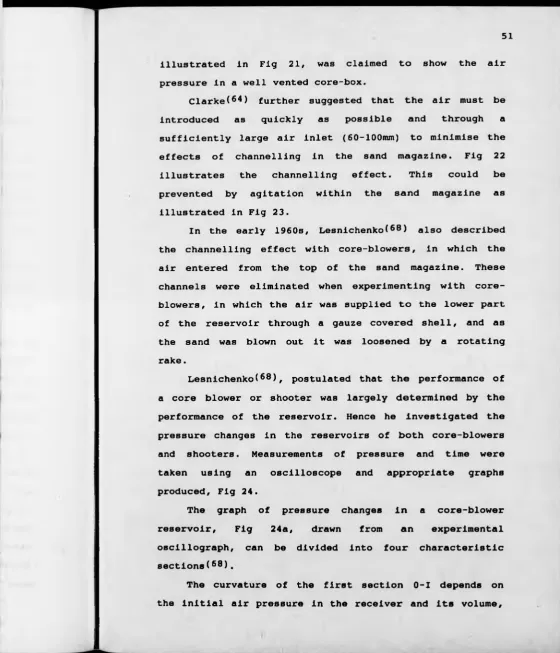
Fig. 24(a). Pressure vs time in core-blower reservoir,
Lesnichenkoi68)
Fig. 24(b). Pressure vs time in core-shooter
reservoir, Lesnichenko(88)
Fig. 25. Movement of layered sand in sand sleeve,
Gelleri80)
Fig. 26. Movement of layered sand in sand sleeve,
Gelleri8 0 )
Fig. 27. Movement of layered sand in sand sleeve,
Gelleri80)
Fig. 28. Air pressure variation in sand sleeve,
Khurtovi 70)
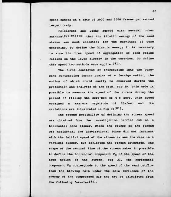
Fig. 29. Movement of the contrasting substance in
the sand stream, Pelczarski(8 1 )
Fig. 30. Speed of sand stream in core-box vs time,
Pelczarskii 81)
Fig. 31. Determination of the horizontal component
of the speed of the sand flow, Pelczarskii 81)
Fig. 32. Variation of core density across and along
the core-box, Pelczarskii8!)
Fig. 33. The shape of the free surface when filling
the core-box with sand, Pelczarski(81)
Fig. 34. Movement of layered sand in sand magazine,
Danko(83)
Fig. 35. Core box filling by two different sands,
Danko(83)
Fig. 36. Core blower
Fig. 37. Core box number 1
Fig. 38. Main body of core box number 1
Fig. 39. Perspex front of core box number 1
Fig. 40. Back of core box number 1
Fig. 41. Front view of core box number 1
Fig. 42. Cross sections of different channels of
core box number 1
Fig. 45. Core box number 2
Fig. 46. Core box number 3
Fig. 47a. Front view of core box number 3
Fig. 47b. Side view of core box number 3
Fig. 47c. Plan view of core box number 3
Fig. 48. Schematic diagram of core box number 2
showing filling time measurement technique
Fig. 49. Blow holes used in the experiments
Fig. 50. Order of experiments carried out on core
box 2 in group 4. All vents open (a total of 30)
Fig. 51. Order of experiments carried out on box 2
in group 6. All vents open (a total of 30)
Fig. 52. Order of experiments carried out on box 1
in group 6. All vents open
Fig. 53. Schematic diagram of core-box number 1
showing the number of different channels and levels 1* to 3'
Fig. 54. Preliminary experiments carried out in sub
group a of group 1 on box 1
Fig. 55. Core-box 1, core-weight vs blow hole area
Fig. 56. Experiments carried out in sub-group a of
group 1 on box 1
Fig. 57. (J)5nun blow hole, all vents open
Fig. 58. <{>5mm blow hole, all vents open
Fig. 59. <|>5mm blow hole, all vents open
Fig. 60. <t>5mm blow hole, all vents open
Fig. 61. (|>5mm blow hole, all vents open
Fig. 62. (|>5mm blow hole, all vents open
Fig. 63. (|>5mm blow hole, all vents open
Fig. 64. <j)1 0mm blow hole, all vents open
Fig. 65. <t>10mm blow hole, all vents open
Fig. 6 6. <t>1 0mm blow hole, all vents open
Fig. 69. (JllOmm blow hole, all vents open
Fig. 70. 0 1 0mm blow hole, all vents open
Fig. 71. (pi Omm blow hole, all vents open
Fig. 72. (|)1 0nun blow hole, all vents open
Fig. 73. (jjlOrnm blow hole. all vents open
Fig. 74. (j)1 0mm blow hole, all vents open
Fig. 75. (pi 5 mm blow hole, all vents open
Fig. 76. (pl5mm blow hole, all vents open
Fig. 77. (pl5mm blow hole, all vents open
Fig. 78. 015mm blow hole, all vents open
Fig. 79. (pl5mm blow hole, all vents open
Fig. 80. (pl5mm blow hole, all vents open
Fig. 81. <pl5mm blow hole, all vents open
Fig. 82. <p20mm blow hole, all vents open
Fig. 83. (p20mm blow hole, all vents open
Fig. 84. (p20mm blow hole, all vents open
Fig. 85. (p20mm blow hole, all vents open
Fig. 8 6. <p20mm blow hole, all vents open
Fig. 87. (pl5mm blow hole, one
each channel open
vent at the end of
Fig. 8 8. 015mm blow hole, one
each channel open
vent at the end of
Fig. 89. <t>15mm blow hole, one each channel open
vent at the end of
Fig. 90. 015mm blow hole, one
each channel open
vent at the end of
Fig. 91. 015mm blow hole, one
each channel open
vent at the end of
Fig. 92. 015mm blow hole, one
each channel open
vent at the end of
Fig. 93. Triangular
the end of blow each
hole - 015mm, one vent i
the end of each channel open
Fig. 95. Triangular blow hole = <J)15mm,
the end of each channel open
one vent at
Fig. 96. Triangular blow hole = ((>20111111, the end of each channel open
one vent at
Fig. 97. Rectangular blow hole = <J)20mm,
the end of each channel open
one vent at
Fig. 98. Rectangular blow hole = ()20mm,
the end of each channel open
one vent at
Fig. 99. <|>5min blow hole, vents up to 2' channel 4 closed
and in
Fig. 100. <J>5mm blow hole, vents up to 2' channel 4 closed
and in
Fig. 101. <(>5mm blow hole, vents up to 2' channel 4 closed
and in
Fig. 102. (j>5mm blow hole, vents up to 2' channel 4 closed
and in
Fig. 103. <t>5mm blow hole, vents up to 2' channel 4 closed
and in
Fig. 104. <j)15mm blow hole, vents up to 2
channel 4 closed
' and in
Fig. 105. <|)15inin blow hole, vents up to 2 channel 4 closed
' and in
Fig. 106. <|)15min blow hole, vents up to 2 channel 4 closed
• and in
Fig. 107. <t>15mm blow hole, vents up to 2 channel 4 closed
' and in
Fig. 108. <t>15mm blow hole, vents up to 2 channel 4 closed
' and in
Fig. 109. <t>5mm blow hole, vents up to 1' closed
Fig. 110. <j)5mm blow hole, vents up to 1' closed
Fig. 111. ()>5mm blow hole, vents up to 1' closed
Fig. 112. 4)5mm blow hole, vents up to 1 ' closed
Fig. 113. <J)5mm blow hole, vents up to 1' closed
Fig. 114. <t>15mm blow hole, vents up to 1' closed
Fig. Fig. Fig. Fig. Fig. Fig. Fig. Fig. Fig. Fig. Fig. Fig. Fig. Fig. Fig. Fig. Fig. Fig. Fig. Fig. Fig. Fig. 117. <)>15mm and 6
blow open
hole, vents in channels
118. ((>15mm
and 6
blow open
hole, vents in channels
119. <J)15mm
and 6
blow open
hole, vents in channels
1 2 0. ((>15mm
and 6
blow open
hole, vents in channels
1 2 1. (|>15mm
and 6
blow open
hole, vents in channels
1 2 2. ((115mm
and 6
blow open
hole, vents in channels
123. (j)15mm
and 6
blow open
hole, vents in channels
124. (|>15mm
and 7 blow open
hole, vents in channels
125. (}>15mm
and 7 blow open
hole, vents in channels
126. (j>15mm
and 7 blow open
hole, vents in channels
127. <j)15mm
and 7 blow open
hole, vents in channels
128. (j)15mm
and 7 blow open
hole, vents in channels
129. Sound core
130. Sound core
131. Core containing spongy areas
132. Core containing spongy areas
133. Core containing spongy areas
134. Core containing voids
135. Core containing voids
136. Core-box 1, filling time vs blow hole area
137. Schematic diagram of core-box number 2
showing the position of the vents and the number of different sections
138. Experiments carried out in sub-group b of
Fig. 140. <|)10mm blow hole, all vents open
Fig. 141. <j)15mm blow hole, all vents open
Fig. 142. <J)15mm blow hole, all vents open
Fig. 143. <J)15mm blow hole, all vents open
Fig. 144. <|)30mm blow hole, all vents open
Fig. 145. <j)30mm blow hole, all vents open
Fig. 146. <j>30mm blow hole, all vents open
Fig. 147. <()5mm blow hole, all vents open
Fig. 148. <j)5mm blow hole, all vents open
Fig. 149. <f>5mm blow hole, all vents open
Fig. 150. <})5mm blow hole, all vents open
Fig. 151. ({>5mm blow hole, all vents open
Fig. 152. Experiments carried out in sub-group b of
group 1 on box 2
Fig. 153. 4>15mm blow hole, vents on section 1 open only
Fig. 154. <t>15mm blow hole vents on section 1 open only
Fig. 155. 4>15mm blow hole, vents on section 1 open only
Fig. 156. (|)15mm blow hole, vents on section 1 open
only
Fig. 157. <|)15mm blow hole, vents on section 1 open only
Fig. 158. <t>15mm blow hole, vents on left hand side of the core box open only
Fig. 159. (pl5mm blow hole, Top 3 vents on right hand
side and Bottom vents of left hand side on section 2 of the core-box open only
Fig. 160. <)>15mm blow hole, Bottom 3 vents on section
2 and vents on section 1 of the core-box open only
Fig. 161. 4>15mm blow hole, Middle 3 vents on section
2 of the core-box open only
Fig. 163.
Fig. 164.
Fig. 165.
Fig. 166.
Fig. 167.
Fig. 168.
Fig. 169.
Fig. 170.
Fig. 171.
Fig. 172.
Fig. 173.
Fig. 174.
Fig. 175.
Fig. 176.
Fig. 177.
Fig. 178.
Fig. 179.
Fig. 180.
Fig. 181.
Fig. 182.
Fig. 183.
Fig. 184.
2 and vents on section 1 of the core-box open only
4>15mm blow hole, Top 3 vents of section 2 and vents on section 1 of the core-box open only
Experiments carried out in group 2 on box. All vents open (a total of 20)
Core box 2, core-weight vs blow hole area
Core box 2, core-weight vs air pressure
Experiments carried out in sub-group a of group 3 on box 1 (All vents open)
Core-box 1, filling time vs air pressure
Core-box 1, core-weight vs blow hole area
Core-box 1, core-weight vs air pressure
Experiments carried out in sub-group b in group 3 on box 2, all vents open (a total of 30)
Core-box 2, core-weight vs blow hole area
Core-box 2, core-weight vs air pressure
Experiments carried out in sub group a of group 4 on box 1. Resin content = 1.05%
(All vents open)
Experiments carried out in sub-group a of group 4 on box 1. Resin content“ 0.35%
(All vents open)
Core-box 1, core-weight vs blow hole area
Core-box 1, core-weight vs air pressure
Core-box 1, core-weight vs blow hole area
Core-box 1, core-weight vs air pressure
Experiments carried out in sub-group b of group 4 on box 2. All vents open (a total of 30)
Core-box 2, core-weight vs air pressure
Core-box 2, core-weight vs air pressure
Core-box 2, core-weight vs air pressure
Fig. Fig. Fig. Fig. Fig. Fig. Fig. Fig. Fig. Fig. Fig. Fig. Fig. Fig. Fig. Fig. Fig. Fig. Fig. Fig. Fig. Fig. Fig. Fig. Fig. Fig. Fig.
186 . Core-box 2, core-weight vs blow hole area
187 . Experiments carried out in
2. All vents open (a total
group 5 on box of 30)
188 . Core-box 2, core-weight vs air pressure
189 . Core-box 2, core-weight vs air pressure
190. Core-box 2, core-weight vs air pressure
191. Core-box 2, core-weight vs blow hole area
192 . Core-box 2, core-weight vs blow hole area
193. Core-box 2, core-weight vs blow hole area
194 . Experiments carried out in sub-group a of
group 6 on box 1. (All vents open)
195a. Core-box 1, core-weight vs blow hole area
195b. Core-box 1, core-weight vs blow hole area
195c. Core-box 1, core-weight vs blow hole area
196a. Core-box 1, core-weight vs air pressure
196b. Core-box 1, core-weight vs air pressure
196c. Core-box 1, Core-weight vs air pressure
197 . Experiments carried out
group 6 on box 2.
in sub-group b of
198a. Core-box 2, core-weight vs blow hole area
198b. Core-box 2, core-weight vs blow hole area
198c. Core-box 2, core-weight vs blow hole area
199a. Core-box 2, core-weight vs air pressure
199b. Core-box 2, core-weight vs air pressure
199c. Core-box 2, core-weight vs air pressure
2 0 0. Pressure vs Time, Geller(69)
2 0 1. Pressure vs Time, Lesnichenko(86)
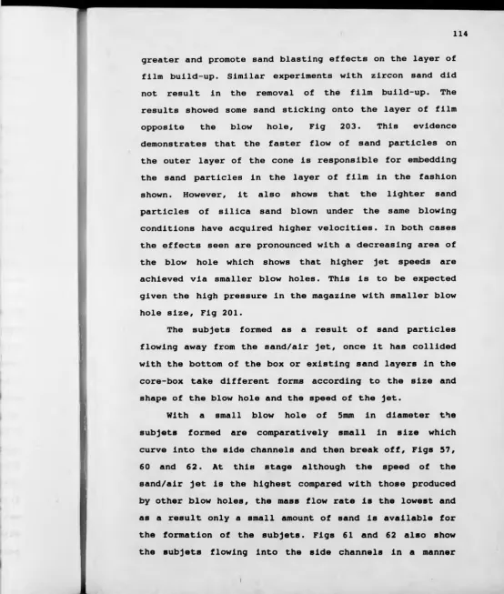
2 0 2. Film removal
jet opposite
of film build- i blow hole
up by sand/air
203. Sand sticking opposite blow' hole
open
Fig. 206. Core-box 3 ,
open
(J>10mm blow hole, all vents
Fig. 207. Core-box 3/
open
(()10mm blow hole, all vents
Fig. 208. Core-box 3 ,
open
(j)10mm blow hole, all vents
Fig. 209. Distribution of forces during collision
the sand particles, after Danko<81)
Fig. 210. Movement of
sand layer
sand particles in core-box
on surface of
Fig. 211. Partially and fully resin
particles
coated sand
Fig. 212a. Core-box 1, core-weight vs resin content
Fig. 212b. Core-box 1, core-weight vs resin content
Fig. 212c. Core-box 1, core-weight vs resin content
Fig. 212d. Core-box 2, core-weight vs resin content
Fig. 212e. Core-box 2, core-weight vs resin content
Fig. 212f. Core-box 2, core-weight vs resin content
The effect of different control variables of the core-blowing process on the mechanism of sand flow inside core-boxes has been studied. These variables included the
core-box geometry, the blowing air pressure, the
sand/binder mixture, the area and arrangement of the core-box vents, and the area and shape of the blow hole.
A high speed cine-camera (64 frames/sec) was used to record the filling of the three core-boxes used. The blown cores were weighed in the boxes on scales accurate to 0.1 of a gram. They were then cured using sulphur dioxide (SO2) and checked for soundness.
The results showed that:
i) The filling pattern within a core-box can be
controlled by the blowing conditions. Different
patterns of filling can be achieved according to different; blow hole sizes and shapes, blowing air pressure settings and core-box venting arrangements, resulting in different degrees of sand compaction in the core-box.
ii) For a given blowing condition increasing the blowing
air pressure and/or increasing the blow hole area to optimum values, gives rise to increasing the overall compaction of the core and its weight. The rate of change in the core-weight decreases as the optimum values of blowing air pressure and/or blow hole area are approached.
iii) The filling time of a core-box with sufficient venting is related to the area of the blow hole and the blowing air pressure. Insufficient venting of a core-box can give rise to prolonged filling times.
iv) Insufficient venting or over venting of a core-box
leads to decreasing the core compaction and weight. One sided venting in the core-boxes used, resulted in faster filling and better sand compaction in those sides.
v) Compaction of the sand in the core-box is achieved
under the influence of; the kinetic energy of the
sand/air jet entering the core-box (Primary
compaction), and the air flowing through the mass of sand in the core-box (Secondary compaction).
vi) Increasing the binder level in the mix led to
the production of stronger cores. However it also
led to core defects in the form of voids in
areas where compaction is largely achieved as a
1. INTRODUCTION
The art of casting metal has its origins in ancient
civilisation. After initial mastery of the art, it became
apparent to founders that to produce anything other than
the simplest of solid castings, a system would have to be
devised to enable internal cavities to be formed within
the casting. It was found that this could only be done
with cores. The early cores were formed in baked clay
which developed into forming cores of sand, mixed with
available binding materials. These cores were used in the
production of such castings as ancient statues and iron
stoves. The casting of bells exerted an influence on core
making.
The 19th Century brought about new developments of
core making, and equipment was made available for mass
production. The cores, usually hand rammed from a
sand/organic binder mix, were heated in ovens to harden.
Core-blowing machines were introduced into core
making shops around 1910. Early progress of the core
blowing process was slow. However, the importance of the
core-blowing machine as a modern means for rapid
production of uniform and high quality cores was
recognised. Core-blowing has thus become a specialised
branch of the foundry trade, and the factors controlling
the success of any particular job are many and varied.
In blowing a core, the core-box cavity is filled by
introducing sand, suspended in a stream of compressed air
which enters the cavity, at high speed through the
blowing holes. The core is rammed by abruptly arresting
allowed to continue on to the atmosphere, exhausted via
vents In the core-box, Fig 1.
When confronted with a core which is to be produced
on a core-blower, a machine of the proper design and the
requirements of the finished cores are known, as far as
sand/binder mix, strength, permeability and other core
physical characteristics are concerned. However, the
questions; how shall the core be placed in the core-box,
and where the blow holes and the vents should be
arranged, as well as the size and shape of these, to give
satisfactory results with a minimum of experimental
effort have to be resolved. In view of the variety of
sizes, shapes and contours of cores required,
difficulties are often encountered in deciding just what
are the best blowing conditions. A working knowledge of
the essential factors of the core-blowing process is
therefore of great interest to pattern-makers and foundry
engineers.
Unfortunately, practical knowledge pertaining to
blowing cores has been confined largely to those who
directly work with core-blowing machine design and are
engaged in the manufacture of the equipment.
In order to reduce core-blowing to engineering
knowledge, it is necessary to systematically study the
process and determine its underlying characteristics.
This requires the investigation of the mechanism of
sand/air flow (ie; sand/air flow stream flowing from the
blowing holes into the core-box cavity), and the motion
of sand particles during the filling of the cavity in the
2. OBJECTIVE
To investigate the mechanism of sand/air flow (i.e.
sand/air stream flowing through the blowing holes into
the core-box cavity), motion of sand particles during the
filling of the cavity in the core-box and core
3. LITERATURE SURVEY
3.1. Core-making Terminology
A core is an aggregate of partially inert materials,
possessing a degree of porosity, and a controlled
mechanical strength to allow the aggregate to be
assembled without breakage, for the purpose of making
internal or external portions of a mouldi1). The major
function of the core is to form internal cavities
surrounded by metal.
Sand cores are made with the aid of core-boxes which
can be repeatedly used to produce a particular core. The
boxes are usually constructed in two or more parts with
pins and guides so that the finished core can be removed.
The cavity in the core-box represents the form or pattern
which is to be reproduced in the finished core.
The core sand grains used in core-making are bound
together with core-binders. With the aid of the binders
sand mixtures are set into cores. The mixtures may have
to be heated to gain the required strength, using core
drying and core-baking ovens. With some binders gasses
are passed through cores, this is known as core hardening
by gassing.
Cores can be assembled to build a whole mould (i.e.
external and internal parts). This necessitates handling
and accurate positioning of the cores which is usually
helped by the use of core-prints which are location
features on other parts of the core or mould half.
Some cores may need extra reinforcement, Fig 2. The
use of sprigs, nails, wire, rod, rod rig construction,
and perforated tube, are common in cores of thin cross
sections, i.e. below 12mm and more than 50mm long(2 ). The
type of reinforcement is determined by the size and
complexity of the core.
Prior to casting, cores may have to be coated using
materials known as core-washes or core-coatings in order
to promote a smooth casting surface.
During the casting operation gasses are normally
evolved from the core binders. These gasses escape
through core-vents and through the natural permeability
of the core mixture. The venting method chosen is
governed by the size and shape of the core, and the core
sand used, Fig 3.
Shrinkage holes can form in cored sections of a
casting when a thick section is isolated from the feeder.
Core-chills can counteract the formation of such
shrinkage holes(2 ). Core-chills are pieces of metal
varying in size and shape, which are placed on the faces
of bosses, pads, ribs, or in the corners of a core-box.
Fig 4 illustrates some different types of core-chills.
[image:26.600.5.573.15.685.2]3.2. Core Sands
Sand consists of grains of mineral matter ranging
from approximately 0.05 to 2mm dia. Common foundry sand
is composed of silicon dioxide, Si02• Silica grains are
often associated with small amounts of feldspar, mica and
other minerals. High grade special sands are sometimes
used for cores and moulds where special characteristics,
such as increased thermal conductivity are required.
Such sands include zircon (Zr Si0 4), chromite (Fe Cr2C>4),
olivine [(Mg, Fe) 2 Si0 4], staurolite (Fe AI5 Si2 O1 2: OH)
and aluminium silicates(3).
Fore modern core practice the basic requirements of
core sands are (4 );
dimensional and thermal stability at elevated
temperatures
suitable particle size and shape
chemical inertness with molten metals
not readily wetable by molten metals
low content of volatile elements
availability in large quantities at reasonable cost
consistent cleanliness and pH values
compatible with the binders used.
3.2.1. Core sand types
3.2.1.1. Silica
Silicon combines with oxygen to form an oxide,
Si0 2, which occurs in a variety of formsf1). Most silica
sand deposits have formed by weathering, i.e. the
geological sedimentary processes and transportation by
wind and water, Fig 5. The composition of the deposits
depends on the nature of the materials that were eroded
and in the manner in which they were deposited(1). During
the depositional processes, classification (i.e.
separation) by size, shape, composition and specific
gravity can take place.
Commercial silica foundry sands are found widely
distributed over the United Kingdom being worked at many
localities. Fig 6 illustrate a selection of foundry
sands, location, characteristics, and properties.
Silica sands are not thermally stable. They expand
by appreciable amount on heating and shrink on cooling.
Their binder requirements, pH, acid values, vary from
deposit to deposit. They are also of comparatively low
density and low thermal conductivity(4 ).
3.2.1.2. Zircon
The element zirconium combines with sodium, calcium,
manganese, iron, titanium, thorium and oxygen to form
eleven different Zr-bearing minerals(4 ). Of these, only
baddeleyite (Zr0 2) and zircon silicate (ZrSi0 4) are mined
on a commercial scale. Zircon is widely produced from
beach sand deposits. These range in age from very young,
as found along the eastern coast of Australia, to very
ancient fossil shoreline deposits being mined in Florida
and Georgia. Malaysia, India, Sri-Lanka and South Africa
are other producers of zircon sands.
Zircon sand has several desirable properties as a
foundry sand(5-®);
lowest thermal expansion of any foundry sand, Fig 7
high thermal conductivity and bulk density giving
about four times the cooling rate of silica
unwetted by most molten metals
[image:28.598.1.576.14.681.2]chemical unreactivity
clean rounded grains which readily accept any type
of binder
superior dimensional and thermal stability at
elevated temperatures
pH is neutral or slightly acid.
3.2.2. Properties of core sands
Based on the origin, the sands vary in grain shape
(Fig 8), grain composition, surface characteristics,
grain size and distribution. These properties in addition
to chemical analysis, sintering point, and expansion,
vitally affect the usefulness and ultimate properties of
the core.
3.2.3. Core sand binders
3.2.3.1. Introduction
Dry cores are composed of a mixture of sand and some
binding material, which causes adhesion between the sand
grains, and which have to be hardened after some further
treatment. Binders can be classified depending on their;
chemical nature, physical form, or hardening process. A
simple division is by chemical nature, i.e. organic, and
inorganic.
3.2.3.2. Requirements
Whether organic or inorganic, the binder should
possess the following requirements;
high dry strength and sufficient resistance to
temperature so as not to collapse before the casting
has solidified to retain its shapei5 )
high collapsibility after casting cools to room
temperature to allow the sand to be easily
removed(1)
minimum evolution of gas to prevent gaseous effects
in castings
minimum absorption of moisture if cores are to be
stored giving a good "shelf life"
good dispersing properties in mixing(^)
minimum stickiness not to create additional labour
in cleaning core-boxes but allow the sand to "flow"
into the box geometry
reasonable bench life in the unmoulded condition
no safety or environmental problems
good economy.
3.2.3.3. Binder groups
3.2.3.3.1. Organic binders
Resin binders are synthetic materials which can be
classified together with cold curing oils as organic
binders(10). These binders are more expensive than
inorganic binders but this is partly offset by the lower
percentage addition (less than 2% compared to the more
than 3% additions for the inorganic binders(5 )). All the
organic binders have excellent breakdown properties which
makes them ideal for the cores of a casting where
accessibility for fettling is difficult, and the
resultant reduced fettling costs make these binders
economical. In general, it may be said that unlike
inorganic binders which are thermally stable and exhibit
little degradation of bonding on heating, organic binders
burn out upon casting, producing gas and producing a
carbonaceous film on the sand grains(10). These
properties are in fact responsible for the good casting
surface finish with these materials, plus ease of casting
knockout and the reclamation of such sands for further
use. A disadvantage is that the generation of gases
during casting can, under certain circumstances result in
casting defects.
There are three major types of organic binders; oil
based, cereals and resins.
3.2.3.3.1.1. Oil based binders
These binders as used in the foundry industry are of
two types; natural and processed oils(5 ).
Natural oils are vegetable and marine oils; linseed,
tung and dehydrated castor oils. These oils dry and
harden on standing. The drying power of an oil depends on
the degree of unsaturation which is represented by the
number of double bonds in the chain (- C = -)(5). The
greater the number of double bonds, the greater the
unsaturation and the greater the drying power(11).
Processed oils may contain unsaturated mineral oils,
synthetic oils and alkyd resins. These oils are
relatively cheap and can be produced from a blend of
oleic and linoleic acids, with glycerol(5 ).
3.2.3.3.1.2. Cereals
Cereal binders are of two types, pregelatinised
starch and dextrine(7). These develop a gelatinous bond
with water(12-13). Cereals improve initial compacted
strength and contribute to collapsibility and ease of
knockout, by decomposing at the casting temperatures.
resistance of dried cores to the absorption of
moisture(7 ).
3.2.3.3.1.3. Resin binders
In the last 40 years there has been a tendency to
replace oils, and inorganic binders such as silicates,
with resins for foundry core binders. This is because of
many advantages that resin binders offer(^). The main
advantages are:
faster curing and higher production rates
in-box curing
increased flowability
easier core break-down and shake-out
improved casting quality
reduced skill requirements in production of cores
and moulds
good economy.
There are many types of resins used, from simple
urea and phenol formaldehyde resins to complex furan
polyal resins(7).
3.2.3.3.1.4. Cold-settina resins
The use of cold-setting resins in foundries began in
the early sixties and coincides with the introduction of
furfuryl alcohol. Cold-setting resins are commonly based
on resin containing furfuryl alcohol, in which
polymerisation reaction results by the addition of a
strong univeral acid, forming a green coloured
condensation product(l°). The reaction is exothermic,
which helps to obtain a consistent-through cure. The
reaction rate is sensitive to temperature and the nature
of the base sand(i4).
Urea formaldehyde/furfuryl alcohol resins were later
developed which exhibit a stronger bond than that
produced with furfuryl alcohol resins, and are more
stable to the effect of heat than urea formaldehyde resin
alone(10).
Today cold-set resins are represented by a range of
materials exhibiting differing physical properties. This
range may be sub-divided as follows;
Urea formaldehyde and furfuryl alcohol modified urea
formaldehyde resins known as furanes, (UF/FA resins)
Phenol formaldehyde (PF resins) and furfuryl alcohol
modified phenol formaldehyde resins, (PF/FA resins).
Both PF and PF/FA resins are characterised by zero
nitrogen contents which eliminate problems due to
pinholing in some alloys(10)
the furfuryl alcohol modified copolymer resins
containing both urea and urea formaldehyde
components called copolymers (PF/UF resins)
Polyurethanes (PU), where a phenol formaldehyde
resin together with a tertiary amine accelerator is
hardened by a dimisosynate MDl(15) (Methylene-
disphenyl-isocynate)
The PF and PU resins do not contain furfuryl
alcohol(1 0).
The catalysts generally used are either phosphoric
acid for furanes(16) (UF/FA) and para toluene sulphonic
acid (PTSA)(17) for the phenolic and phenolic furanes. A
general guide for copolymer resins is that PTSA is used
to catalyse resins with nitrogen contents below 5%,
The range of cold curing resins available to
foundrymen represents a very efficient type of cold
setting process. The main advantages associated with the
use of these binders are, the good flowability of the
mixed sand, low gas evolution on casting, high hot
strengths, excellent breakdown and high tensile strength
which enable cores to withstand handlingi*0) (1®).
Against these advantages there are limitations
imposed by the physical properties of resins. For
instance, the problem of nitrogen pinhole defects exists
with certain UF containing resins. Fining flaw problems,
can be encountered with PF and PF/FA resins. Owing to the
formaldehyde content, unpleasant odours are produced
during mixing, leading to unpleasant working conditions
if provisions for adequate ventilation is not provided.
3.2.3.3.1.5. Thermo setting resins (the shell process)
The shell process, or the Croning process, consists
of mixing sand with powdered phenol formaldehyde (PF)
resin of the type known as a novalac(19). A mixture of
the PF resin and sand, when blown into a heated core-box,
cures by heat to give a rigid shape. However, problems
were encountered due to segregation of the resin in the
sand mix which gave rise to coating defectsi10).
Curing of Novalac resins takes place when reacted
with hexamethylene tetramine or hexamine (CH2)6 N4. The
curing takes place at a temperature of 200-230°C. The
presence of nitrogen in hexamine could lead to
nitrogen/hydrogen pinhole defects in the castings. To
eliminate this defect a modified novalac has been
pre-coated sand containing 2.5% to 4% PF resin. The pre
coating of the sand grains by the resin is carried out by
one of two methods; the Warm and the Hot process.
In the Warm process, hexamine is incorporated at the
start of the process, together with a wax which acts as a
release agent and improves the flowability of the
sand(1 0).
In the Hot process, the mixture is heated to 130°C
and then cooled to below the melting point of the resin
and the catalyst is introduced in the form of a solution
of hexamine in water(10).
In the hot-box process either urea formaldehyde
furfuryl alcohol (UF/FA), phenol formaldehyde (PF) or
(PF/UF) are used(17). These resins are mixed with
solutions of salts usually ammonium chloride, which are
stable at ambient temperature, but on heating release
acid which reduces the pH of the resin causing a rapid
cross linking and thus setting.
The UF resins although cheap and excellent for hot-
box production also give rapid breakdown on casting but
have a high nitrogen content which limits their unblended
use. The furane resins give much faster setting times and
higher strengths and low gas evolution(^).
3.2.3.3.2. Inorganic binders
Cement, clays and sodium silicates are classified as
inorganic binders. These are the lowest costly binders
and some have been used since founding began(2®"2 3).
3.2.3.3.2.1. Sodium silicates
Aqueous sodium silicates have been used as foundry
recently In the cement silicate, fluid sand and ester-
silicate processes. The term sodium silicate refers to a
three ingredient system; silica, sodium oxide and water
giving the Si0 2~Na2 0-H20 ternary system(5 ).
Since the adoption of the carbon dioxide sodium
silicate process in the early 1950's the usage of this
technique has grown continually with silicate bonded
sands being used for both mould and core-making
processes ( ) . On the passage of CO2 gas through the
sand, hardening takes place via two mechanisms; the
formation of the silica hydrogen bond and the physical
dehydration of the aqueous silicate(10) . A characteristic
of the hardening process is that in most cases the
initial as gassed strength is low requiring care in
handling of cores. On storage, the strength levels
generally continue to rise owing to further dehydration
of any unreacted sodium silicates.
3.3. Mixing
The purpose of mixing is to secure distribution of
core mixture constituents to a smooth, lump free
consistency. The binder should be finally distributed as
a thin film round each sand grain(7).
The mixer units range from batch types such as wheel
design mullers, blade mixers and even cement mixers to
the continuous mixer units.
Condition of the sand is highly important, free from
fine impurities, such as clays, moisture and oily
materials(24). Antisegregation devices in storage bins
and hoppers are applied to maintain a constant surface
area to be coated. These devices prevent fines from
reaching the mixers at irregular rates which could have a
significant and unexpected effects on the sand mixture
properties.
The configuration of the sand grains has also an
effect. Angular or irregular shaped grains, require more
binder than rounded sand grains. Where sand reclamation
is used, angular grains tend to become rounded after
several coatings, if the original binder remains on the
grain in the form of a fused-on deposit(24).
Mechanical parts of the equipment should be designed
so as to prevent excessive scrubbing motion of the sand
against itself which could result in removal of any
coating. Attrition of the sand mixture is undesirable
since it hinders formation of binder on sand grains as
well as causing overheating which tends to decrease bench
Mixers are designed to maintain good mechanical
performance. Overloading the mixer can cause granular
damage or undesired heating which could give rise to
evaporation of solvents and consequently, reducing the
bench life and tensile strength characteristic of the
sand-mix as well as increasing the binder
requirements(24 ) .
Mixers of all types should be enclosed to prevent
solvent vapour loss as well as objectionable odours.
Sand should be fed into the mixing chamber at a
constant rate and temperature(25).
Pumps, when used should be of the variable type with
facilities for easy adjustment and recording of volume
within fine tolerances( ) .
Pumps, valves and plumbing must be compatible with
the chemicals they come in contact with. Acid catalysts
used with furane and phenolic hot box processes, for
example, can be extremely damaging to pumps and valves.
The same is true for the peroxides used in epoxy, furane
3.4. Core-making
In the manufacture of castings often a mould is used
to define the outer shape of the castings, whilst the
internal configuration is formed by means of a core.
Cores are most commonly used as inserts in moulds to form
design features which would be difficult or impossible to
produce by direct moulding.
3.4.1. Properties required for core-making
It is a prime requirement that both moulds and cores
be sufficiently refractory in nature to prevent
penetration and erosion by the molten metal(1 0).
Cores are often almost totally enclosed by molten
metal with the core print providing the only means of
venting. It follows that the volume, rate of evolution,
and chemical nature of any gases generated from the
binder are of major consideration if defective castings
due to blow holes and pin hole porosity are to be
avoidedi1®). A further requirement is that the binder
must degrade at the casting temperature in order to
prevent hot tearing and to facilitate removal from the
casting at knock-out(*).
The requirement of the sand-binder mix to be rammed
or blown into the core-box to produce cores with uniform
density implies that the sand mix should be non-sticky
and free flowing. Furthermore, in order to ensure that
dimensionally accurate castings are produced, the ideal
binder system would be such that the curing reaction
would be completed prior to stripping from the
The choice of a core-making process Involves a
consideration of the requirements mentioned, together
with the ability to produce dimensionally accurate cores
at the optimum rate for the foundry at minimum cost.
3.4.2. Core-maklno processes
3.4.2.1. The shell process
In its infancy, the shell process was limited to
shell mould production. The mixture made was a simple
mechanical mixture of sand and powdered resin suitable
for dump box operations, Fig 9, but unsuitable for
blowing purposes due to the resin segregation that took
place in a core blower (19). However, the process
presented tremendous possibilities towards complete
automation of foundry operations.
In the shell process, sand precoated with a thermo
setting resin, is either blown into an electrically or
gas heated core-box usually maintained at 250°C-300°C, or
dumped under the influence of gravity onto the pattern
platei1®). The former produces a shell of controlled
thickness, whereas, in the latter case, the shell
thickness is dependent on the pattern temperature and the
sand holding time on the pattern.
Since the sand mix is dry it is easily blown into
the core-box at relatively low pressure. Cores can be
made hollow, thus facilitating the removal of gases
generated by core during casting.
Dimensional accuracy of cores is high and excellent
breakdown is obtained with all but the low melting point
Disadvantages of the shell process are; the
requirement to heat the core-box to high temperatures,
the high cost of metal core-boxes and the high cost of
precoated sand(17). Core fumes and operator fatigue due
to high temperatures are also inherent disadvantages.
3.4.2.2. The hot-box process
This process, a follow on from the shell process,
was possible by the development of sand mixtures based on
liquid resin binders, in which curing is accomplished by
heating in the presence of a catalyst(5 ). The fact that
hot-box mixtures are wet allows the use of conventional
rather than special blowers designed for blowing dry
mixtures. As a result of the thermo-setting properties of
the resin employed, a hardened cured skin is produced
which enables stripping to be carried out in a very short
time. Hardening is further continued after stripping hot
core to give a uniform curingi10).
The main application of the hot-box process lies in
long production runs of similar core designs thus
lowering the cost of heating metal core-box. Changing the
boxes in production may involve several hours to heat the
box to the working temperature. Cores have excellent
breakdown properties but also unpleasant fumes associated
with the curing process.
2 . 4 . 2 .3. c<?l<a gettin g core-making processes
In cold setting processes the sand binder mixture is
hardened to a point where the core can be stripped from
the box, coated if necessary, and used without the need
Cold setting processes have revolutionised both
mould and core-making processes. They have reduced and In
some cases eliminated the need for skilled moulders and
core makers(24). The absence of heating permits
relatively inexpensive core-boxes and heat related
problems such as; expansion, contraction and warpage of
boxes are not apparent(17).
Increasing applications of cold setting processes
has been at the expense of oil sand binders for the
volume production work of small to medium sized cores,
and in place of the loam and dry sand cores for larger
work(15).
The cold setting processes offer improved
dimensional accuracy of castings through consistent
accurate core production direct from the core-box. Cores
that previously were made in two halves to produce flat
surfaces for core drying can be made as one, thus
reducing the number of cores required(26).
Improved casting soundness is achieved through
higher core rigidity and reduced gas evolution.
Reductions in the core production costs are achieved
in terms of labour and production equipment. Cost of
manufacture, maintenance and operating of core driers and
core sizing machines are eliminated. Floor previously
occupied for these operations are thus recovered. Skilled
labour can usually be replaced with semi-skilled or
unskilled labour.
Main advantages of the cold setting processes lie in
the form of energy conservation and other ancillary
3.4.2.3.1. Sodium silicate processes
Experiments with sodium silicate as a binder for
sand were carried out in 1898(27) England.
Sodium silicate processes are widely used in many
types of foundries, to produce castings from a few
grammes in weight to many tonnes, across the whole range
of metal alloy compositions(15). Three main types of
sodium silicate processes differ mainly in the method by
which the sand-binder mix is blended(17);
Silicate CO2
Powder hardened silicate
Ester-silicate
3.4.2.3.1.1. Silicate CO? Process
The silicate CO2 process began to be adopted on a
commercial scale in the 1950s, and today the process has
achieved widespread use(19) .
One of the problems of the CO2 process that quickly
became apparent in the early days, and is still a problem
today, is that of poor core breakdown at the shake-out.
The development of the CO2 process in the 1970s,
made a huge impact on the foundry industry(26). It
consisted of preparing a slightly damp mixture of sodium
silicate and sand, which was hand rammed into wooden
core-boxes and hardened by the Injection of CO2 gas. The
gas, from bottles is injected into the core-box by means
of tubes or masking plates. Fig 10 illustrates examples
of systems used. The core is hardened in seconds and this
makes the process commercially competitive apart from the
in the environmental problems are unmatched by any
organic process(28).
The process uses many commercial sands. The main
sand requirement is that it should have a low clay
content which reduces the ultimate core strength(27).
The sand which contains 3%-6% sodium silicate can be
mixed in most types of mixers (10). Mixed sand can be
either rammed or blown into the core-boxes. The hardening
reactions of carbon dioxide with water present in the
sodium silicate solution, produces sodium carbonate and
silica gel. The amount of CO2 gas required to cure a core
is affected by the positions and number of vents in the
core-box, sand and CO2 temperatures, gas pressure and
volume, and the method used to introduce the gas into the
core. The influence of the main process variables have
been examined by Atterton(29), Haley(^®), Thompson(31),
Taylor(32) and Lange(33),
The advantages of the process are(28);
high dimensional accuracy of the hardened cores
adaption of the process to suit small quantity
production methods, and high volume techniques
relatively low cost
freedom from unpleasant fumes either in mixing or
casting.
The disadvantages are the comparatively low tensile
strengths of the as-gassed cores and the poor
breakdown(7 ) .
3.4.2.3.1 .2. ppw<tec hardened silicate processes
These processes involve the addition of powder
the sodium silicate binder to form a rigid bond. Compared
to gaseous and liquid hardeners the powders, finely
ground to below 200 BSS mesh, are difficult to mix, and
setting is generally slower!17).
The powders used include ferro-silicon, dicalcium
silicate and various types of cement.
The ferro-silicon is used in the Nishiyama
process(34). This hardening reaction produces hydrogen
gas which may give rise to explosion hazards!3®).
Dicalcium silicate, as used in the fluid sand
process, is a major constituent of a number of
metallurgical slags as well as certain types of Portland
cement. It reacts with sodium silicate by removal of
water to produce the silicate glass. The initial reaction
rate is slow!1®).
All of these latter processes have found limited
applications and some have been superseded by the ester-
silicate system.
3.4.2.3.1.3. Ester-silicate process
The hardeners used in this process are organic
liquids, esters, (an ester is the generic name for the
product of a reaction between an organic acid and a
polyhydric alcohol!3®)). The hardening is achieved by a
two part chemical reaction between sodium silicate and
organic esters, the most significant reaction being a
decomposition of the esters by the alkali to form alcohol
and an acid which produces gelling of the sodium
silicate. Consistent through hardening is achieved by
This process is used for the manufacture of small
and heavy castings over a wide range of alloy
compositions. The process is also used for moulding as a
facing material subsequently to be backed by green sand.
Olivine, chromite or zircon sands are widely used
with this process in the steel industry. In some cases it
has been found possible to replace these sands with
silica sands, since it is possible to obtain glass hard
and smooth surfaces on the cores and moulds(*5).
Many organic esters such as, monocetin, diacetin,
triactin and diethylene glycol diacetate can be used to
gel sodium silicate. The various blends produce a range
of setting times(17).
The cores produced using this process are free from
finning defects sometimes encountered with resins and
there are no unpleasant fumes associated with the
process. Problems due to nitrogen pinholing are also
avoided(37).
3.4.2.3.2. Cold setting phenolic furane process
The many organic synthetic resins, such as, UF/FA,
PF/FA, FA/F, and PF are hardened through polymerisation
at room temperature under the influence of acid
catalysts, such as, para-toluene sulphonic (PTSA),
phosphoric and sulphuric acids. By suitable choice of
resin and catalyst stripping times from three minutes to
three hours can be achieved(15).
Sands of low acid demand are used, the grain size
and shape largely determining the binder level for
required strengths. Chromite and zircon facing sands are
This process can be used to manufacture moulds and
cores for a wide variety of jobbing castings from less
than half a kilo-gram to 50 tonne in most grades of
ferrous and non-ferrous alloys(15). The process is
sometimes used for boxless moulds in competition with
green sand where it is often competitive when capital
cost is taken into account.
The most common method for production using this
process is the pattern flow system, in which the core
boxes are brought to a continuous mixer by roller track
and the mixed sand is discharged into the box. Since the
sand is quite flowable either vibration or hand-ramming
is sufficient to compact the sand(1 0).
An alternative system used, to the pattern flow
method, is the multi-stage carousel type machine.
If coatings are required, water based types are to
be preferred. Spirit based coating can be used provided
great care is taken to ensure that excess solvent is not
allowed to cause softening of the resin bond resulting in
metal penetration and burn on(10).
3.4.2.3.3. The-SQ2 process
The different types of SO2 process involve the
mixing of the sand with organic resins such as phenolic-
furane and an oxidising agent such as methyl ethyl ketone
peroxide (MEKP). The sand either rammed or blown into
core-boxes sets very rapidly as SO2 gas is passed through
it. The SO2 reacts with the peroxide to form SO3, which
dissolves in the water present in the binder to form
sulphuric acid (H2 SO4) inducing rapid exothermic
The system although still used In the U.S.(38) and
some parts of Europe(39), has not been extensively used
in the industry, primarily because of two problems,
firstly environmental problems of SO2 gas and secondly
resin build-up film on the core-boxes which influences
dimensional accuracy and stripping of the cores. The
removal of this film has also been difficult and costly.
Recent research resulted in the development of new
techniques that considerably decreased the film build up,
and also enabled the cleaning of the film to be carried
out extremely rapidly and cheaplyi40).
3.4.2.3.3.1. Furan-SO? process
This was the original SO2 cold-box process(38), in
which a chemically bonded system uses resins employed in
the self setting phenol-furan processes(17). Resin
addition depends upon the sand surface and grain
distribution. As little resin as 0.7% of the weight of
the sand can be used for the production of high quality
cores.
Core blowers/shooters can be used to blow or shoot
the sand-binder mixture into the core-boxes. The boxes
can be made in a wide variety of materials such as, epoxy
resin, aluminium and cast iron.
Gassing is carried out by liquid SO2 carried by
pressurised nitrogen via a vaporiser. All pipes including
solenoid valves conveying SO2 are in stainless steel.
Gassing times can be as little as 0.5 sec to as much as 5
sec, depending on the size of the cores. Purging with
compressed air is carried out after gassing to remove the
scrubbing tower containing a 1 0% solution of caustic soda
in water.
Several advantages are offered by the
process( 3 8 <39 /41) . The core strength immediately after
gassing and the hot strength, are high. This enables the
casting of water jackets in engine block heads, or other
intricate cored work, with good dimensional accuracy(^2).
The excellent surface finish allows castings. Superior
breakdown of the cores at the shake-out is another
advantage. The bench life of the furan-S02 sand-binder
mix and of cores is also good. Mixed sands can be kept in
the machine hoppers up to three or four hours, and still
keep a constant core making cycle time(39). The colour
changes of the cores could be used as a process control.
3.4.2.3.3.2. The epoxv-SO? process
The epoxy-S0 2 process was developed in order to
bring about improvements over the already existing furan-
SO2 process(38).
The process consists of a two part binder system.
The first part is a combination of epoxy resin and
oxidiser. The second part is epoxy resin with synthetic
modifiers such as acrylic. Total binder level is based on
the weight of the sand and is generally in the range of
0.6%-l .4% depending on the type of sand and physical
strengths required of the core!38) .
The gassing operation is the same as that employed
in furan-S02 process with the advantage of roughly
halving the gassing and purging cycle times.
The following advantages have been
reported(38,39,42)j elimination of sand setting in
hoppers and less wasted sand between core-box change have
Increased up-time and productivity, a major reduction in
maintenance time spent to clean sand mixers, hoppers,
sand magazines and exhaust valve screens, and delivery
belt, consistent flowability and blowability throughout
the shift, significant reductions in core scrap at the
machine, normally caused by sand in which the binder has
degraded with time, absence of nitrogen, water,
formaldehyde or phenol in epoxy results in fewer blow
defects, higher core strength and hardness are developed
at resin levels lower than that of furan-S0 2, thermo
plasticity properties lead to the reduction of veining
and hot tearing of castings combined with excellent
shake-out.
3.4.2.3.3.3. The FRC process
This process uses an organic binder composed of
vinyl unsaturated urethane oligomers which contain
reactive carbon-carbon double bonds, an organic
hydroperoxide that initiates the free radical
polymerisation, silane adhesion promoters which provide
cores with excellent shelf life, and a diluted activator
gas to induce curing(*3).
The curing is Induced through the application of
nitrogen diluted sulphur dioxide gas with a typical
concentration of 1%-10% sulphur dioxide followed by a
purge of nitrogen or dry air to flush excess activator
gas from the cores(44).
The process has been successfully applied to a wide