University of Warwick institutional repository: http://go.warwick.ac.uk/wrap A Thesis Submitted for the Degree of PhD at the University of Warwick
http://go.warwick.ac.uk/wrap/67010
This thesis is made available online and is protected by original copyright. Please scroll down to view the document itself.
OF
TRANSITION
METALS
WITH
f
CARBON,
NITROGEN
AND' OXYGEN'
by
P. ,S'.'
BELL
A dissertation submitted
to the University of Warwick for admission to the degree of
Doctor of Philosophy
tvlnlORANDUM
This dissertation is submitted to the University
of Warwick in support of my application for admission to
the degree of Doctor of Philosophy. It contains an account
of my own work performed at the Department of Physics of
the University of Warwick in the period October 1968 to
October 1971 under the general supervision of Dr. M.H.Lewis.
No part of it has been used previously in a degree thesis
submitted to this or any other University. The work
des~ribed in this thesis is the result of my own independent
research except where specifically acknowledged in the text •.
I should like to thank Professor A.J.Forty for
making available to me the facilities at the Department of
Physics. I am extremely grateful to Dr. M.H.Lewis for
his interest and advice during the course of this work,
and especially in the preparation of this thesis.
My thanks are due to the Science Research Council for
providing the financial support of a -Research Studentship.
I would also like to thank Messrs. L.Bulmer and M.Davies
of the University of Warwick Library for their helpful
service.
Finally, I would like to thank my wife Sandra, for her patience and encouragement throughout the period
ABSTRACT
11any carbides, nitrides, and oxides of the Group
IVa and Va transition metals show large deviations from
stoichiometric compositions. These deviations are
accomp-lished by the subtraction of the interstitial nonmetal
atoms, or in some ~ases the metal atoms, from their lattice
sites. The formation of superlattice structures resulting
from the ordering of the remaining atoms and.vacancies is
then possible. The stru~tures and modes of formation of
these superlattices have been examined for a number of
compounds using transmission electron microscopy and
elect-ron ·diffraction.
The nominally NaCl-type titanium and niobiu~
monocarbides were examined within the composition limits
TiCO•45 to TiCO•6S and NbCO•70 to NbCO•95 respectively.
In the first system the cubic superlattice based on the
composition Ti2C wa~ found, while niobium carbide showed
similarities to vanadium carbide in the formation of
ord-ered structures based on the composition Nb6C5•
Three possible structures for Nb6CS' two with monoclinic
and one with trigonal symmetry, are discussed in terms of
periodic low. energy planar faults within the carbon-atom
sublattice.
Although the two hexagonal close-packed
hemi-carbides, V2C and Nb2C, show very small deviations from
the stoichiometric composition, ordering is possible in
the carbon-atom sublattice since this contains 50% vacancies.
In both hemicorbides two ordered structures were found,
stable at high and low temperatures. The high-temperature
temperature modifications, although slightly different,
both possess orthorhombic symmetry.
Titanium and vanadium mononitrides (NoCl-type)
were examined within the ranges of composition TiNO•50
In .neither case was the
presence of long-range order detected. However the hcp
heminitride, V2N, exhibited nitrogen-atom orqer giving an
£-Fe2N-type structure.
The NaCl-type monoxides of titanium and vanadium ,
were examined within the ranges of composition TiOO•7 to
Ti01•25 and VOO•70 to V01•35• In vanadium monoxide a
tet-ragonal superlattice based on the unit cell composition
The com plex st ruc t ureo f this sup e
r.-lattice, which results from vanadium-atom order, contains
vanadium atoms in interstitial (tetrahedrally coordinated)
posftions, surrounded by four vanadium vacancies, as well
as helices of vanadium vacancies. Isothermal
heat-treatm-ents enabled a partial phase diagram to be constructed
showing the conditions for the formation of the V2440320
superlattice. Electrical resistivity measurements showed
that vanadium monoxide was semiconducting down to
liquid-nitrogen temperature.
In titanium monoxide the structures of the two
superlattices with compositions Ti01•0 and Ti01•25 were
confirmed. Examination of quenched specimens in the
'region TiOO•7 to TiOO•9 showed a metastable ordered domain
structure formed by the segregation of oxygen vacancies
small fraction of an orthorhombic superlattice formed by titanium vacancy segregatipn onto every third (110) plane.
Two further investigations were made which were not directly concerned with superlattice structure.
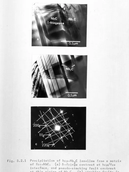
Examination of vanadium and niobium carbides within the nominal hemicarbide and monocarbide two-phase region showed the occurrence of ~ompounds with unit cells based on long repeat sequences in the stacking of close-packed metal-atom planes. In both carbides the t~phase, ~ontaining twelve planes, and also in· niobium carbide the (-phase, containing nine planes, were found. The accommodation of carbon atoms in the t- and t-phases resulting in poss-ible· ordered structures are discussed. Also, the modes of transformation between structures with different sta~k-ing sequences are critically examined.
The second investigation was an in situ study in the electron microscope of the effect of electron irr-adiation on the superlattice V2440320. Disordering was observed, resulting from atomic displacements caused by collisions with electrons. The disordering process was
structures adopted by the different superlattices are explained in terms of the type of atomic bonding and the electronic structure in these transition-metal compounds.
PUBLICATIONS
Certain parts of the work reported in this
thesis have been published in scientific journals, as
follows;
(1). "Non-Stoichiometric Vacancy Order in Vanadium
Monoxide", P.S.Bell and M.H.Lewis, Phys. Stat. Sol. (a),
7, 431 (1971).
(2). "The Ordered Distribution of Carb~n Atoms in Titanium Carbide", P.S.Bell and M.H.Lewis, Phil. Mag.,
24, 1249 (1971).
(3). "A Superlattice with Monoclinic Symmetry Based
on the Compound V6C5", J.Billingham, P.S.Bell and M.H.Lewis,
Phil. Mag., 25, 661 (1972).
(4). "Vac ancy Short-Ran ge Orde r in Subs toic h iometr ic
Transition-Metal Carbides and Nitrides", Part 1, "Electron
Diffraction Studies of Short-Range Ordered Compounds",
J.Billingham, P.S.Bell and M.H.Lewis, Acta Cryst., Accepted
For Publication (1973). (Part 2, "Numerical Calculation
of Vacancy Arrangement", M.Sauvage and E.Parthe)
(5). "Non-Stoichiometry in Ceramic Compounds",
M.H.Lewis, J.Billingham and P.S.Bell in "Electron Microscopy
and Structure of Materials", ed. G.Thomas (University of
California Press, Berkeley, 1972). (Proc. 5th. Int. Mater.
Symp. University of California, Berkeley, Sept. 1972).
(6). "The Crystal Growth of Transition-Metal
Inter-stitial Compounds by a Floating Zone Technique",
J.Billingham, P.S.Bell and M.H.Lewis, J. Cryst. Growth,
CHAPTER 1 INTRODUCTION
1.1 Interstitial Compounds 1
1.2 Nonstoichiometry 3
1.2.1 General Principles 3
1.2.2 Structural Accommodation of 5
Nonstoichiometry in Crystals
1.2.3 Binary Interstitial Compoun~s 6
with the ~aCl-type Structure
1.3 Order - Disorder Transformations
7
1.3.1 Long-Range Order (LRO)
7
1.3.2 Short-Range Order (SRO) 9·
1.3.3 Nucleation and Propagation of LRO 12
1.4 Aims of the Present Work 13,
REFERENCES 15
CHAPTER 2 EXPERIMENTAL METHODS
2.1 Crystal Preparation 16
2.1.1 Possible Methods of Crystal'Growth
17
(i) Growth from the vapour
17
(ii) Growth from solution 17
(iii) Growth from the solid 17
(iv) Growth from the melt
2.1.2 Starting Materials
2.1.3 Vertical Floating Zone Technique
(i) Vanadium monoxide
I (ii)
(
111.
. .
)
Vanadium nitride
Titanium nitride
2.1.4 Horizontal Zone Technique
(i) Vanadium monoxide
(ii) Titanium nitride
2.1.5 Solid-State Sintering 26
2.2 Electron Microscopy and Diffraction 28
2.2.1 Specimen Preparation 28
2.2.2 Electron Diffraction 29
2.2.3 Image Formation in the 30
Electron Microscope
2.2.4 Interface Analysis
2.2.5 Transmission Modes
2.2.6 Multiple Diffractio~
2.3 Crystal Sttucture Determination
2.3.1 Computational Method
2.3.2 Crystallographic Notations
REFERENCES 32 33 34 34 36 38
40
CHAPTER 3 CARBIDES WITH AN FCC METAL-ATOM STRUCTURE
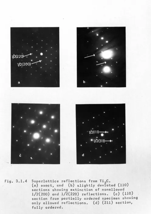
3.1 Titanium Carbide 42
42
43
43 3.1.1 Introduction
3.l~2 The Ordered Compound Ti2C
(i) Electron microscopy and
diffraction
(ii) Structure of the ordered
44
compo un d Ti2C
3.1.3 Precipitation of a-Ti
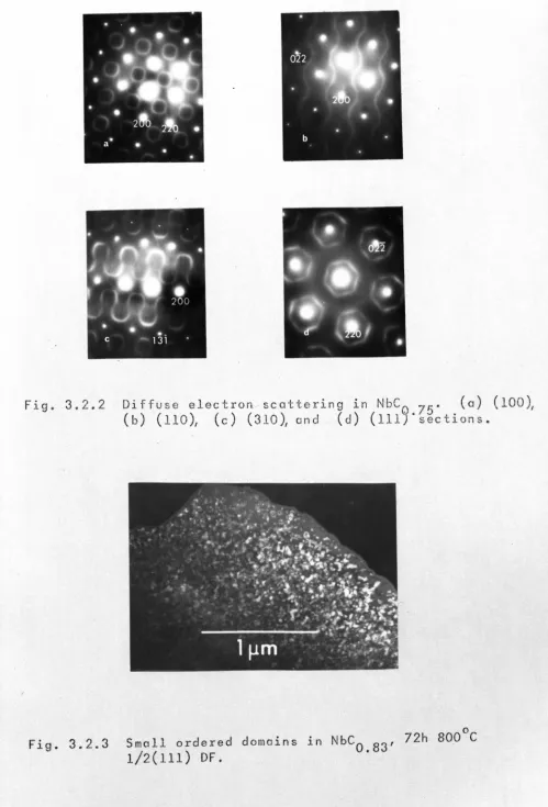
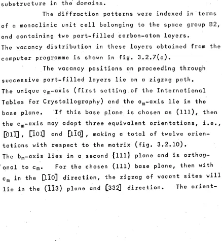
3.2 Niobium Carbide
46
47
3.2.1 Introduction 47
3.2.2 Electron Microscopy and Diffraction 48
3.2.3 Structure of the Ordered Compound 49
/ Nb6C5
(i) The trigonal P31 modification 50
(ii) The monoclinic
B2/m
modification 51(iii) The monoclinic B2 modification 52
3.2.4 Discussion of the Proposed 53
Ordered Structures
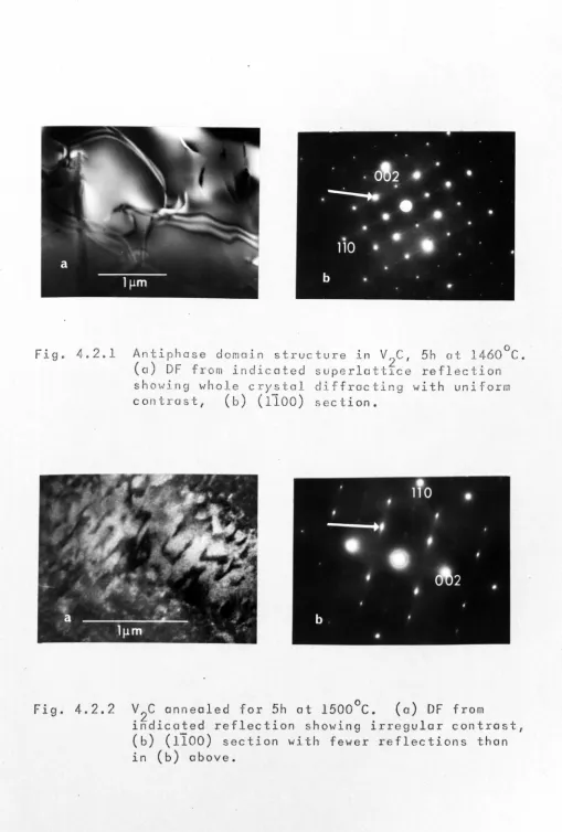
4.2 Vanadium Hemicarbid~2£L 60
4.2.1 High-Temperature Structure in V2C 60
(i) Electron microscopy and60
diffraction
(ii) Structure of the high-temperature 63
ordered phase
4.2.2 Low-Temperature structure in V2C 65
(i) Electron microscopy and 65
diffraction
(ii) Structure of the low-temperature 66
ordered phase
4.2.3 Specimens Containing Two Ordered 67
Phases
4.3 Niobium Hemicarbide (Nb2£L 67
4.3.1 High-Temperature Structure in Nb2C 67
(i) Electron microscopy and 67
diffraction
4.3.2 Low-Temperature Structure in Nb2C 68
(i) Electron microscopy and 68
di ffraction
(ii) Structure of the low-temperature 68
ordered phase
REFERENCES 70
CHAPTER 5 DEVIATIONS FROM FCC AND HCP METAL-ATOM
STACKING
.1
5.1 Introduction
(i) Stacking sequence notations
(ii) Stacking faults in fcc and
hcp structures
71
71
(iii)
Structures with mixed metal-atom 74stackin~
5.2
Compounds Containina Stackina Faults75
5.2.1
Electron Microscope Contrast75
(i) Stacking faults
75
(ii) Partial dislocations 76
5.2.2
Observation of Stacking Faults77
(i) Niobium carbide 77
(ii) Vanadium hemicarbide 79
(iii) Vanadiu~ nitride 80
(iv) Titanium nitride
81
5.2.3
Discussion of Stacking Fault 84Configurations
(i) Summary of electron microscope 84
observations
(ii) The accommodation of nonmetal 84
atoms at stacking faults
5.3
Structures with Mixed Metal-Atom87
Stacking
5.3.1
Analysis by Electron Diffraction87
5.3.2
Previous Observation of Structures87
with Mixed Metal-Atom Stacking
5.3.3
Observation of Structures with 88Mixed Metal-Atom Stacking
~-phase vanadium carbide
88
(ii) ~- and. E-phase niobium carbide 90
5.3.4
Discussion of ~- and (-phases 91;
(i)
Stability with respect to 91temperature and composition
(ii) The accommodation of carbon atoms- 93
.
stacking sequences
REFERENCES 103
CHAPTER6 TRANSITION-METAL NITRIDES
6.1 Introduction 106
6.1.1 Phase Relationships in Transition- 107
Metal Nitrides
,.
(i)
Titanium nitride 107(ii)
Vanadium nitride 107(iii) Comparison with other nitrides 108
6.2 Titanium Nitride 108
6.2.1 Electron Microscopy and 108
Diffraction
6.3 Vanadium Nitride 109
6.3.1 The VN/V2N Eutectic 109
6.3.2 Electron Microscopy and 110
Diffraction
(i)
(ii) Vanadium mononitride Vanadium heminitride 110 110 112 REFERENCESCHAPTER 7 OXIDES WITH AN FCC METAL-ATOM STRUCTURE
7.1 Introduction
7.2 Vanadium Monoxide
7.2.1 Previous Work
7.2.2 Characterization of Vanadium
Monoxide
(i) Chemical analysis 116
(ii) Density and lattice parameter 116
113
114
114
116
measurements
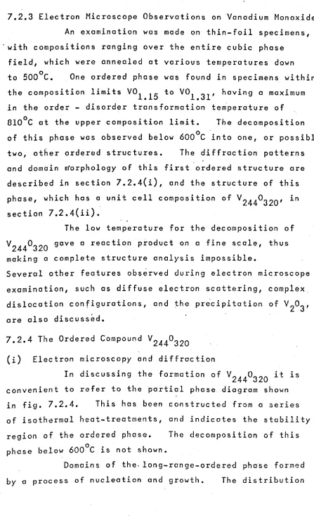
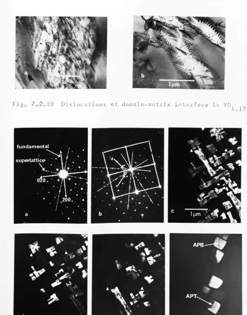
< 7.2.3 Electron Microscope Observations 118
7.2.4 The Ordered Compound V2440320
(i)
ElectrQn microscopy anddiffraction
(ii)
Structure of the orderedcompound V2440320
7.2.5 Low-Temperature Structure in
Vanadium Monoxide
118
118
123
126
(i)
Electron microscopy anddi ffrac tion
126
-'
(ii) Structure of the low-temperature 128
forms of vanadium monoxide
7.2.6 Further Electron Microscope Studies 129
on Vanadium Monoxide
(i) Diffuse electron scattering ·129
(ii) Microstructure within the range 130
VOl•lO to VOl•lS
(iii) Precipitation of V203
7.2.7 Electrical Measurements on
Vanadium Monoxide
131
132
(i)
Previous work 132(ii) Experimental results 133
(iii)
Discussion of the electrical 134properties of vanadium monoxide
7.3 Titanium Monoxide
7.3.1 Previous Work
7.3.2 Electron Microscopy and
Diffraction
135 135 137
.'
(i) The ordered compound Ti°1.0
(ii) The ordered compound TiOl•25
(iii) Transition structures
.
7.3.3 Discussion of the Transition
137 138
139
141
Monoxide
APPENDIX 7.2
Calculation of Vacancy Concentrations 145
REFERENCES 146
CHAPTER 8 THE EFFECT OF ELECTRON IRRADIATION
ON VANADIUM MONOXIDE
8.1 Introduction 149
8.2 Experimental 149
8.3 Radiation Induced Disordering 150
(i) Electron microscope observations 150
(ii)
Mechanism for displacements in 152vanadium monoxide
(iii)
Vanadium atom displacementenergy, Edv
8.4 Two-Stage Disordering Mechanism
for Vanadium Monoxide
153
157
(i) Theory
(ii) Numerical calculation
8.5 ~diation Induced Ordering in
Vanadium Monoxide
(i) Electron microscope observations 161
(ii)
A possible mechanism for 162157
158
161
radiation induced ordering
in vanadium monoxide
REFERENCES 165
CHAPTER 9 CORRELATION AND DISCUSSION OF ORDERED
VACANCY DISTRIBUTIONS
9.1 Origins of the Ordering Force 166
9.2 Bondina Mechanisms in Interstitial 169
Compounds
(i) Metal-nonmetal bonding 170
predominant
(ii) Metal-metal bonding predominant 172
(iii) Recent theories of bonding 172
9.3 The'Origin of the Ordering Force 175
in Interstitial Compounds
9.4 Formation of the Observed Long-Range- 176
Ordered Variancy Distributions
(i) Carbides and nitrides with an fcc 176
metal-atom structure
(ii) 'Carbides and nitrides with an hcp 178
metal-atom structure
(iii) Oxides with an fcc metal-atom 179
structure
9.5 Short-Range Order in Transition-Metal
IBO
Carbides, Nitrides, and Oxides
(i) Models of microdomain formation .1BO
9.5.1 Correlation of Diffuse Scattering 182
Observations
9.5.2 Interpretation of Diffuse 1B3
Scattering Distributions
(i) Titanium and vanadium monoxides 183
(ii) Cubic carbides and nitrides 187
REFERENCES
189CHAPTER
ONE
INTRODUCTION
1.1 Interstitial Compounds
Compounds of transition" metals with the elements hydrogen, boron, carbon, nitrogen and oxygen are referred to as interstitial 'compounds because the small nonmetal atoms are usually situated in the interstices of the metal-atom sublattice. Interest in these ~ompounds arises from their unusual combination 'of metallic and ceramic properties, viz. good electrical conductivity, hardness and mechanical strength, high melting point and chemical stability.
The factors determining the crystal structures of transition-metal interstitial compounds were originally examined
by
Htlgg(1).
An empirical rule governing the structure of these compounds is found from the atomic radius ratio of the metal and nonmetal atoms, rX/rM• Simple structures are found when this ratio is less than 0.59, and complex ones for larger ,values. This critical value in radius ratio does not produce a sharp division in structure types, since atomic radii vary according to coordination and bonding type, but represents the upper limit in a region of overlap.- 2
-simple hexagonal etc. The interlayer interstices are denoted by the Greek letters a,
p,
and y. Thus. the octa-hedral interstices between an A and B layer arey
positions, and the tetrahedral interstices a and ppositions.The projections of the A, Band C positions onto the close-packed planes are coincident with the a,
p
and y positions respectively.In fig. 1.1.1 the structures of some common
types of HUgg compounds are shown. Complexities may arise from the following:
(1) Periodic combinations of the simple metal-atom stacking sequences may result in structures related to poly-types.
(2) Incomplete occupancy of the interstices in the metal-atom structure provides the possibility for various distributions (either ordered or disordered) of the inter-stitial atoms.
.,
The research described in this thesis is concer-ned mainly with a study of these structural variations for a range of H8gg compounds based on the transition-metal
elements, titanium, vanadium and niobium. In the following sections a number of important topics are introduced which are relevant to the structural analyses described in the subsequent Chapters. Of particular importance are the structural variations that accompany gross deviations from the stoichiometric ratio of metal and nonmetal atoms.
o
•
nonmdaJ
atoms
Fig. 1.1.1 Some of the common structure tvpes for interstitial compounds. (a) f;c NoCl-type
•.• AyBaCpA •.• (b) h~p NiAs-type .•. AyByAyB .••
Cc)
simple hexagonal ~C-type ••• AyAyA •••t
t
G
G
Ir
,
/,
/
/
,
MJX MX. MlJ
X ....
(0)
(b)
Free energy - composition (G - X) curves for (a) stoichiometric and
Cb)
non stoichiometric- 3 - .
1.2 Nonstoichiometry
1.2.1 General principles
The concept of non stoichiometry provided
one of the great philosophic arguments in the history
of chemical thought. On the one hand, Dalton's laws
of constant and multiple proportions based on the st0dy
of simple substances,stated that different species of
atoms combined in simple and fixed proportions, while
on the other hand, Berthollet suggested that .compounds
could exist where these rules did not apply. The former
drgument found favour· due mainly to the lack of examples
showing deviation from Dalt~n's laws. However Kurnikow,
in his work on metallic compounds, found several phases'
. . " that existed over a range of composition (nonstoichiometric)
which he called 'Berthollides', as opposed to those of fixed
composition (stoichiometric) which were called 'Daltonides'.
The work of Schottky and Wagner (2) on the
statistical thermodynamics of solid phases showed that the
occurrence of a Daltonide was a limiting case, and that all
compounds contained a small number of defects at finite
temperatures. Although the number of these defects may
vary considerably with temperature,~:distinction is
generally made between compounds where even at high
temperatures the concentration of defects is very small
(less than
0.1%),
and those which show gross variabledepartures from a stoichiometric ratio. Borderline
cases will occur, and furthermore a given compound
showing considerable nonstoichiometry at high temperatures
may well have a very' narrow homogeneity range at low
temperatures.
The free energy - composition (G - X) curve
for the stoichiometric compound is sharply pointed, and
The small number of defects present may be of several types,
e.s. Schottky (vacancy), ~renkel (vacancy interstitial pair).
Their detection is made by special techniques such as
electrical resistivity, and optical absorption (for colour
centres). The G - X relationship for a non stoichiometric
compound presents a broad shallow curve which may well be
asymmetric about the stoichiometric composition (3,4).
It follows that the width of the homogeneity range depends
on the shape,of the G - X curve, since the compositions
of coexisting phases are given by the common tangent points
for adjacent G - X curves as shown in fig. 1.2.1.
An important factor that determines the extent
of rronstoichiometry is the endothermicity of the defects.
For 'a compound which exhibits,nonstoichiometry, the energy
needed to create defects will be low, and the gain ,in energy
from the extra configurational entropy will be high. For
a stoichiometric compound, the energy needed for defect
production cannot be counterbalanced.
Above a low concentration the defects present
in a solid may no longer be considered to form an ideal
solution, and the interaction between defects muit be
_taken into account. The interaction may be attractive,
leadi~g to clusteri~g, or repulsive, leading ,to superstructure
ordering. At thermodynamic equilibrium the structure of
a solid compound is that which has the lowest free energy.
This free energy is determined by two competing processes,
minimization of internal energy with a state of perfect
;
order, and maximization of entropy via random order.
The first process will dominate at low temperatures, the
second at high temperatures. Thus a phase which at' high
temperatures has a broad homogeneity range with a random
5
-a series of ordered phases with narrow homogeneity limits. This presupposes the atta~nment of equilibrium, which in the case of a major rearrangement of defects will be cont-rolled by atomic diffusion. Thus depending on the contr-ibution to the free energy that results from ordering, the high temperature random state may be retained in a metastable conditidn at low temperatures.
1.2.2 Structural Accommodation of Nonstoichiometry in Crystals Although Be~thollide phases were first found in intermetallic compounds, a large number of nonstoichiometric phases has been found in the compounds of transition metals. These include, hydrides, borides, carbides, nitrides, sili-cides, phosphides and chalcogenides. Many binary and tern-ary nonstoichiometric oxides exist. These often have
extremely complex structures which can only be satisfact-orily visualized as chains, layers, cages, etc. of coord-ination polyhedra. Nonstoichiometry can be achieved in· the following five general ways for a compound MX;
(1) Substitution. An excess number of M atoms can occupy vacated X sites or vice versa.
(2) Interpolation. Sites which are normally vacant ~re occupied by excess M or X atoms, or by the addition of a third element.
(3) Subtraction. Atoms of M or X (or both in unequal proportions) may be missing from sites normally occupied.
(4) Shear Structures. Vacant sites of M, but more. ,.usually X~ form planar arrays which collapse by shear,
C?ccupied. Termination of the phase field before,the
stoichiometric (VCI•O) c~mposition is quite common for' these
carbides, and vacancies in the metal sublattice do not occur.
For the, nitrides there is often a limiied extension of the
homogeneity range above the stoichiometric composition, as
well as large substoichiometric deviations. Thus for
titanium nitride the h~mogeneity range is from TiNO•6 to
TiNl•16 (6). Nitrogen excess is achieved by metal-atom
~acancie~, and even the stoichiometric composition contains
a small number of vacant sites on both sublattices (7).
For oxides, compounds in which the metal exhibits
its theoretical maximum valenc~ are normally found. This
is reflected in monoxides which show large deviations on
either side of the stoichiometric composition. In an
early investigation by Ehrlich (8), the titanium monoxide
phase field was found to extend from TiOO•7 to TI0l•25•
At the metal-rich end the titanium sublattice is fully
6ccupied, while the oxygen sublattice is fully occupie~ at
7
-occur in both sublattices, and the stoichiometric composition
is better represented by the formula TiO.8500.85' than by
TiOl•O•
For a number of the carbides, nitrides and oxides
of transition metals, ordered arrangements of non stoichiometric
vacancies have been detected. The major part of the work
described in this thesis is concerned with the structure
of these ordered distributions. The following section
contains a description of order - disorder transformations,
and of the physical techniques for the analysis of ordered
structures. Particular emphasis is placed on the use of
diffraction methods which have been extensively used in
this research.
1.3 Order - Disorder Transformations
Development in the theories of order - disorder
'transformations has been a consequence of the observation
of superlattices in metallic alloys. However, most of the
principles involved in these theories are applicable to the
.
systems forming the subject of the present investigation.
Although in the past diffra~tion effects have been closely
linked with X-ray analysis, the methods developed are
general to other diffraction techniques.
1.3.1 Long-range o~der (LRO)
The occu~rence of LROcan be established when
there is a difference in the occupancy of two equivalent
sublattices of the crystal. It should be pointed out In
this respect that Hagg phases consist of metal and nonmetal
atoms which are restricted to their own sublattices up to
·the melting point. Thus.all 'the lattice points of, for
example, the Noel-type structure form a simple cubic lattice,
which is subdivided into two equivalent fcc sublattices
process of lattice subdivision may be conti~ued indefinitely,
and thus LRO in the prese~t instance will involve a
rearrange-ment of one species of atoms and vacancies on a primary
fcc sublattice. Although there are three components,
metal and nonmetal atoms, and vacancies, the system may
be regarded as binary since the atoms on the fully occupied
primary sublattice'(usually the metal atoms) playa passive
role in the ordering process.
The possible degree of LRO depends on composition
and temperature. For a binary alloy with atomic (or vacancy
·and atomic) fractions xA and xB' the Bragg - Williams (9)
LRO parameter is, given by,
S
=
(xAa- xAp)=
(xBp - xBa)where xAa etc. is the number of A atoms on correct (a) sites.
When the atomic fractions correspond to the stoichiometric
composition of the superlattice, S has a maximum value of
unity for perfect order; and is lero for random order.
For off-stoichiometric I fractions, S must always be .less than
unity. In the original Bragg - Williams theory the energy
'needed to accomplish the interchange Aa~Ap (disordering
energy per atom) was assumed to be directly proportional
to S,and thence the degree of LRO was found to decrease
continuously at,an accelerating rate with increasing·
'temperature, reaching.a value of zero at the criticai
t.emp e r ctu r e T •
c
There are several techniques for detecting, LRO
: such as changes in specific heat, electrical conductivity,
and differential thermal analysis. However the structure
determination of a superlattice is invariably made by one
of three methods, X-.r'ay,'neutron, or electron diffraction.
9
-as the result of LRO give rise to extra (superlattice) reflections besides those ~lready present (fundamental) characteristic of the disordered state. The structure
factor for a reflection hkl can be written in the general form,
where the summation is taken over all atoms in the unit cell ~ith coordinates U,V,w. f(a) i~ the scattering power of each atom for the. particular type
ot
incident radiation. The intensity of fundamental reflections is not usually influenced by ordering, while the superlattice reflection intensities will depend on the degree of order such that,An arbitrary degree of LRO may be determined by diffraction measurements only for a binary alloy. The number of order parameters not accessible by diffraction alone is given by (n-2)(c-l), where n is the number of atomic species, and c the number of sublattices describing the structure. For higher-order systems it may be possible that for some fortuitous combination of scattering factors and degree of orde~ no superlattice reflections are observed despite th~ presence- of LRO.
1.3.2 Short-range order (SRO)
While LRO is defined in terms of sublattice ;occupation, SRO considers an atom and its neighbours with
The most convenient description of the state of SRO is given
by the set of Warren SRO Goefficients almn (ll),·thus,
pAB _ pAB
lim Imn
The integers l,m,n define a particular lattice site according
to the relation,
where a11 a2 an d a3 a re the translation vectors of the (cubic) unit cell. pADlmn is the probability of finding a 8 atom
as an (lmn) neighbour of an A atom. pAB is the limiting
lim
value of the probability for large R, and can usually be
taken as equal to xB• Only for a binary alloy is there
one independent set of atom position probabilities. For a
state of perfect LRO, the SRO coefficients attain maximum
positive or negative values. However when there is no
overall LRO, the degree of SRO may be quite high, but will
decrease as the temperature is raised above Tc•
An alternative viewpoint considers the SRO state
to be achieved by a successive division of the LRO state
by antiphase boundaries. When the ordered domains are
sufficiently small, the sharp LRO diffraction peaks can be
broadened such that the resulting intensity has a diffuse
appearance (characteristic of SRO), although the total
intensity of the diffuse scattering will be the same as
for the LRO superlattice reflections, since the amount of
,disorder introduced at the antiphase boundaries is very
small. This model implies fluctuations in the degree of
SRO between neighbouring domains, while in the stati~tical
11
-whole crystal is implied.
The detection Qf SRO is more difficult than LRO.
While nuclear magnetic resonance (NMR) techniques (12) may give
some additional information on the atomic configurations,
diffraction methods have proved most useful. SRO is one
of several phenomena thot produce diffuse scattering. Others,
such as atomic-size effects,clustering, particle-size and
antiphase boundary broadening, are relevant to order
-disorder transformations in alloys, and in any quantitative
study the intensity produc'ed by these different effects
must be separated. For a binary alloy AB the SRO intensity
is directly related to the coefficients 01 in,
mn
N is the number of atoms irradiated, and fA and fSare the
atomic scattering factors. The his are continuous
coord-inates in reciprocal space equal to one-half the usual
Miller indices at the reciprocal lattice points. The term
before the summation is the Laue monotonic scattering which
is present even when there is complete disorder. The a 's
, th Imn
usually converge ,to zero after about the 10 coordination
shell. It is often fourid that the SRO intensity is c~ntr~d.
about the positions where the LRO ,superlattice reflections
would exist, suggesting that the preferred SRO configuration
is similar to that in the LRO state.
For SRO 0100 is negative. However, the theory
lis equally applicable to the clustering of similar atoms,
w her e 0100 is po sit iv e • Sot h e ffee t s giv e simil a r d iff use
scattering, and a distinction between these two possi~ilities
is not always easy due to the presence of size-effect diffuse
scattering. This latter scattering is caused by static
displa~ements from the exact lattice positions when the
1.3.3 Nucleation and propagation of LRO
Order-disorder transformations are usually
first- or second-order reactions. The first-order reaction is characterized by a discontinuous jump in the degree of LRO to zero at the critical temperature T. There will
c
also be 0 two-phose region where ordered and disordered
parts with different compositions will coexist. For 0
second-order reaction there is no two-phase region, and the ordered structure may show a considerable range of composition. Raising the temperature of the ordered phase results in a conti~uous decrease in the degree of LRO to zero at T •
c
There are two general processes for the formation of the ordered structure from the disordered matrix.
(1) Nucleation and growth is the typical mechanism for ci first-order reaction. Discrete ordered domains
may'nucleate either homogeneously in the disordered matrix, or heterogeneously at crystal imperfections such as grain boundaries or dislocations. Further growth of the ordered regions is controlled by long-range diffusion if the ordered phase has a different composition from the ~atrix, or by odv9ncement of the domain - matrix interface when the two phase~ have the same composition. When adjacent domains impinge, various types of'boundary may result. If the unit cell axes of the orde~ed structure in the adjacent domains are similarly directed, then an antiphase boundary will result when the ordering of each domain was initiated on a different sublattice. In other instances various types
antiphaserelation. 13 antiphaserelation.
-. (2) Continuous ordering, typical of a second-order reaction, may be describe~ as the homogeneous development of order throughout the matrix, where no discrete nucleation site ~an be identified. As the transformation proceeds, the increase in the overall degree of long-range order will eventually lead to the formation of ordered domains
separated by antiphase boundaries. 1.4 Aims Of The Present Work
On account of their unusual physioal properties, the carbides, nitrides and oxides of transition metals are potentially useful materials. Although these.co~pounds are based on simple crystal structures, the explanation of these properties in terms of fundamental physical concepts is' incompletely understood. A particular feature of these compounds is the tendency to show large variations in
compo-sition, and yet to retain the same structure. The intro-duction of non stoichiometry via the subtraction of atoms from lattice sites should,howeve~ lead to the formation of ordered phases at sufficiently low temperatures.
The main objectives of the present work are
Apart from the obvious facility of direct observation of
the ordering process, the .greater scattering power of light
atoms for electrons than X-rays, makes the use of electron
microscopy combined with selected area diffraction invaluable
for the study of these materials. The techniques used
for the preparation of crystalline specimens and the methods
of structure analysis by electron microscopy and diffraction
are described in Chapter 2.
In the specific field of xacancy order in
non-stoichiometric refractory ·compounds, there have been several
reports of ordered phase formation, and where relevant,
these have been reviewed at the beginning of each.Chapter.
Carbides based on fcc (TiC, NbC), hcp (V2C, Nb2C), and mixed
sequences of fcc and hcp metal-atom stacking (VC, NbC) are
examined in Chapters 3, 4 and 5 respectively. Chapter 6
~escribes the work on nitrides (VN, TiN), while the two
oxides,
vo
and TiO, are studied in Chapter 7. A furtherstudj on vanadium oxide, involving radiation damage in the
electron microscope, is presented in Chapter 8. In Chapter 9
the factors which influence the formation of the various
vacancy distributions are discussed collectively.
- 15 .:.
REFERENCES
1. G.HHgg, Z. Phys. Chern:, B6, 221 (1930); B12, 33 (1931). 2. \-J.Schottky and C.Hagner, Z. Phys. Chern. I B11, 163(1930).
3. R.F.Brebrick in "Progress in Solid State Chemistry",
Vol. 3, ed. H.Reiss (Pergamon, New York, 1967). 4. F.A.KrBger, Phy's. Chern. Solids, 29, 1889 (1968).
5. E.Rudy, St.Windisch and C.E.Brukl, Planseeber. Pu1vermet., 16,,3 (1968).
6. A.Brager, 'Acta Physiochim. URSS.,
l!,
617 (1939). 7. P.Ehrlich,z.
Anorg. Al1g. Chern., 259, 1 (1949). 8. P.Ehrlich, Z. Anorg. Al1g. Ch e m, , 247, 53 (1941). 9. H.L.Bragg and E.J.Williams, Proc. Roy. Soc., ~,699 (1934).
10. H.A.Bethe, P'r oc ,' Roy. Soc., Al50, 552 (1935).
11. J.M.Cowley, Phys. Rev., 77, 699 (1950); J. Appl. Phys., 21, 24 (1950).
CHAPTER
nw
EXPERIMENTAL
METHODS
2.1 Crystal Preparation
The various stages of crystalline perfection towards the homogeneous, defect- and strain-free single crystal are attained with increasing degrees of difficulty, and a compromise is usually made to suit the requirements of the particular investigation. For transmission electron microscopy an electron transparent area of crystal is required. The type of specimen from which such a thin area is to be
obtained will often be determined by some other requirement, e.g. from a post-mechanical test specimen, and also on the methods of thinning. available and the desired size of the thin area. For a study of crystal structure by electron microscopy using the fragmentation method for specimen
preparation (described in section 2.2.1), the initial material need only have a low degree of perfection.
The most important factors that restrict the method of crystal growth for a material are, reactivity towards container and atmosphere, and stability towards thermal decomposition. The form of the available starting m~terial, and the desire for close control over composition may also influence the method used. In the following
17
-2.1.1 Possible methods of crystal growth
(i). Growth from the vapou~
In chemical transport crystals are produced by
the thermal decomposition of a volatile compound onto a
substrate. The number of compounds that may be grown by
this method is limited by the availability of a suitable
carrier gas. However a large number of vanadium oxides
with compositions between V203 and V02 have been grown using
TeC14 (1,2), and titanium carbide has· been grown using TiC14,
methane and hydrogen (3). Usuallyth~ rate of growth is
low,and only small single crystals can be obtained.
Direct v~porization of elemental constituents
under vacuum onto a substrate to produce thin crystalline
films has been used for niobium carbide (4). However,
considerable caution must be used to avoid contaminatio~
by residual gases in the 'vacuum system.
·(ii) Growth from solution
In solution growth crystals ore precipitated
(at temperatures below their melting points) from a
super-saturated solution, produced by slow cooling or flux evaporation.
The use of this method is restricted by the availability
of fluxes with a very lo~ solid-solubility in the precipitated
crystals. There is also very little control over the
composition of nonstoichiometric. materials.
(iii) Growth from the solid
Large grain-sized rods, and in some cases single
'crystals of transition-metal carbides, have been produced
by the high temperature strain a~nealing method developed
by Fleischer and Tobin (5). It is claimed that this method
can give crystals free from macroscopic defects (cracks,
t ) and virtually· free from ~ic~~scopic defects
pores, e c. ,
(dislocations etc.). Its wider application is limited to
materials where suitable rods for initial straining can .be
Another method of growth from the solid is by
sintering in powder form ~omponent elements (or suitable
compounds of the elements) at high temperatures. Although
the resulting material is often porous and polycrystalline,
this method is rapid and may be applied to any material
which has reasonable stability below its melting point, and
where component powders may be obtained in a finely divided
and pure form. This method has been used for a number of
compounds in the present work, and is described in greater
detail in section 2.1.5.
(iv) Growth from the melt
This is the most widely used method for growing
lar~e single crystals, and a number of techniques have" been
devised"for different materials. These may be subdivided
according to, the method of containing the molten material,
the heat source, and the environmental conditions during
growth. The floating zone technique is a crucible-free
method, a~d is used where high purity single crystals are
required." Several transition-metal borides and carbides
have been grown by this method using high frequency (HF)
"induction heating and a high pressure of inert gas to reduce
vaporization (6-8).
There is also a number of possible methods for
crystal growth where the molten material is ~ontained in
a crucible, such as the Bridgeman and Czochralski techniques.
Of particular interest are cold crucible methods where the
material is held, without contamination, on a water cooled
hearth usually made from copper. A cold crucible Czochralski
method employing arc 'melting has been used for obtaining
single crystals of several high melting point compouhds (9).
The Verneuil or flame fusion process is suitable
19
-composition is difficult for nonstoichiometric compounds. Howeve~ some transition-m~tal carbides have been grown by
this method (10).
Since suitable refractory crucibles for containing these particular types of high melting point compounds are unavailable, the floating zone technique, and melting in a water-cooled coppet boat have presently been used.
2.1.2 Starting materials
Details of the powders use~ for the preparation of specimens are given in Table 2.1. The purest commercially available powders were used. High purity vanadium metal is particularly difficult to obtain, and unless sealed in on airiight container the powder is rapidly contaminated.
A particular feature during sintering was the
.
TABLE 2.1
Starting Materials
element or powder purity source
compound size llm percent
Ti 100 . 99.5 (a)
V <10 99.2 (b)
Nb <30 99.9 (a)
C 99.999 (a)
VC <100 99.8 (b)
TiN <80 99.9 (c)
VN <80 99.1 (c)
Ti02 1 99.5 (a)
,"
V205 99.99 (b)
..
(a) Koch Light
(b) New Metals and Chemicals
- 21
-2.1.3 Vertical floating zone technique
This method wa~ used for the growth of vanadium monoxide and the vanadium heminitride (V2N) - vanadium rnononitride eutectic, as well as the attempted growth of titanium nitride. Although the objective of this method to produce single crystals was unsuccessful, polycrystalline specimens of the vdnadium compounds were produced.
Sintered rods of the three compounds having different X/M ratios were prepared f~om powd~r mixtures of the respective metal with, vanadium sesquioxide (V203, prepared by reducing V205 in hydrogen at 5000C), vanadium
nitride (VNI•O)' and titanium nitride (TiNI•O). The blen-ded powders were packed into rubber tubes (10-15mm diameter, approximately 150mm length) and sealed with a rubber cap~ Room.temperature hydrostatic pressing to 50 tons psi was carried out at the BSA Group Research Centre, Birmingham. Since only straight rods would be of use, additional rigid-ity was given to the rubber tubes by wire-mesh cages.
For the two nitrides the addition of 2 wt.
%
of paraffin wax binder was necessary in order to facilitate pressing. For vanadium. monoxide, good pressing was obtained without the use of 0 binder, due to the more granular natureof the V203 after reduction.
The nitrides were dewaxed and sintered in vacuum at 500°C and 15000C respectively. For the growth of
van-adium monoxide it was found that the formation of a molten zone could only be achieved if the starting rod had a high 'density. This required prolonged sintering (about SOh) at
15000C in an alumina-tube vacuum furnace. Higher
vanadium monoxide rods were slowly heated and cooled in the alumina tube furnace, the~ were often badly bent and frequently broken, thus considerably reducing the' number of suitable
rods obtained from a given amount of the initial starting powders.
The crystal growth apparatus has been previously described by Billirigham et al.
(11),
and is shown schematically in fig.2.1.1.
The main featur~ 1S the provision for the growth of crystals in ambient gas pressuresqf up to 20 atmospheres. The top of the specimen is attached to a graphite holder by a tantalum pin, and the graphite holder is attached to a stainless steel holder by another pin, this latter holder being screwed into the upper pull-rod. The bottom of the specimen rests without pinning in asimilar series of holders. Several designs of HF heating coil were tried, and finally a three-turn coplanar arrangement was found to give best results for all materials.
(i) Vanadium monoxide
The occurrence of cracked and low density st6iiIng
.
rods made the formation of an initial molten zone'difficult. As the rod was heated,the centre shrank inwards leaving a cracked outer skin which was considerably cooler than the inner region. Increasing the power caused melting of the~inner region which would then suddenly overrun through a crack in the outer skin. This problem was more serious for the high oxygen-content samples, since these c~ntained ,a relatively greater amount of the low density V203•
Howe~eG after initial melting of the centre portion, the power was held constant and a:complete molten zone formed after about thirty minutes.
The crystals were grown by passing the zone in d" t" t 10 /h und"er 15 atmospheres of an upwards 1rec 10n a mm
were varied from VOO•70 to
a/v
ratio, although in some helium. Crystal compositions~upp~r pull-rod
5p4Zcimcznottotchment
--_rII
_viewing port
hf coil
cooling water
---lower pull-rod
cases only short lengths of crystal were traversed before a terminating overrun occ~rred. The grain-size was found to inc rea sew it h the. 0
/v
rat i0 , howe v e r those cry s tal 5 'vIit hcompositions above the oxygen-rich phase boundary were slightly cracked.
(ii)
Vanadium nitrideAlthough the growth of vanadium nitride had not been attempted prior to this present work, the a~ailable thermodynamic data (12,13) suggested··thatthere would be a large equilibrium nitrogen pressure. Since the melting temperature increases with the
N/v
ratio, it was expected ,that the equilibrium nitrogen pressure would increaseext-rem~ly rapidly at the melting points of the higher nitrogen-content specimens.
The crystals were grown under th~ same conditions as vanadium monoxide, except that mixtures of helium and nitrogen, totalling 15 atmospheres, were used.
The maximum nitrogen partial pressure was limited to 10 atmospheres.
Above this pressure there was severe arcing between the coil and specimen, and excessive heating of the chamber walls. The final composition of the crystals depended on the nitrogen pressure, and was independent of the initial rod composition (within the range VNO•6 to VNI•O). For 0-2 atmospheres of nitrogen, the crystals consisted of the hexagonal V
2
N-phase with a large fraction of needle-shaped precipitates of the primary vanadium - nitrogen solid solution (fig. 2.1.2). For 2-10 atmospheres of nitrogen, coarse-grained crystals of a eutectic between V2N and cubicvanadium nitride were obtained (see fig. 6.3.1 and section
Fig. 2.1.2 Two-phase microstructure consisting of precipitates of the primary vanadium - nitrogen solid solution in a matrix of vanadium heminitride (V2N).
(Scanning electron micrograph)
molten zone. One such crystal is shown in fig. 2.1.3.
(iii) Titanium nitride
The reported arc melting of titanium nitride
(of uncertain composition) under 3 atmospheres of nitrogen
(14), served as an approximate guide to the nitrogen partial
press~res that would be required to produce the cubic
mono-nitride (in this c;se considerably less than for vanadium
mononitride). However, when the rods were heated near .
their melting point theY'expended considerably and became
porous, and then could~ot be melted due to the resultant
loss of power-coupling with the HF coil. After attempted
melting the specimens contained many small cube-shaped
crystallites. Local changes in composition were also
observed as regions of different colour, i.e. silvery
white, low nitrogen, to golden yellow, high nitrogen.
None of the sample rods with NITi ratios from 0.4 to 1.0
could be melted by this method.
2.1.4
Horizontal Zone TechniqueA water~cooled copper boat was used for preparing
titanium nitride, and additional samples of vanadium monoxide.
This method of melting was developed by Stirling (15)"
Both the high frequency primary current in-the work coil,
and the secondary induced current in the boat, induce
currents in the same direction in the specimen. Although
the exact nature of the melt - boat interface is uncertain,
it is probable that a few points of the specimen r~moin
!solid and in contact with th~ boat, while the rest of the
specimen is levitated a small distance off the surfaci of
the boat. Titanium (3)~and niobium (16) carbides have
o 0' •.
been melted by this method at 3020 C and 3600 C respect~vely.
Powder mixtures could ~ot be melted in the boat, and the
starting materials consisted of pieces of pressed and
25
-Two s~zes of boat were made. The first larger boat was used for vanadium monoxide, while the second boat
with a smaller HF coil-to-sample separation (giving a greater heating effect) was used for titanium nitride. The boats were constructed from standard 1" and 3/4" Yorkshire copper tube. A depression to hold the specimens was made by
pressing a cylindrical steel tool, of approximately the same size as the specimen to be m~lted, onto the surface of the tube to a depth such that the axis of the tool coincided with that of the tube. Fig. 2.1.4 is a schematic diagram showing the complete assembly. A closely fitting silica tube
surrounds the boat and fits into "0" ring seals in the brass end~caps, which ha~e further seals onto the copper tube. The boat is attached to a sliding carriage which can be traversed by means of a lead screw driven by a variable-speed motor. A small overpressure of helium was used for vanadium monoxide, while titanium nitride was heated in mixtures of helium and nitrogen.
(i) Vanadium monoxide
When the whole sample was melted simultaneously a small hole running d6wn the centre of the ingot was left, due to solidification.proceeding inwards from the surface. Traversing the sample with a horizontal molten zone overcame this p~oblem as the solidification front was then nearly vertical. There was a pinch effect on the melt which caused it to be pushed away from the centre of the coil, thus increasing the cross-section of the solidified portion.
,.
Small adjustments to the final composition could be mode by using pieces of starting material with different compositions. The samples were homogenized by melting
four times. After each melt the ingot was broken up and the pieces redistributed in the boat before remelting.
The re·sulting material was always polycrystalline, although
·
,000
silica tube
slidingcarri~ to I~ad sc~w
and varioble-5pftd motor
- 26
-the oxygen-rich speC1mens contained grains several millimetres in dimension. The zone ~as traversed rapidly (20cm/h) in order to reduce vaporization, since slower speeds gave no increase in the grain-size.
(ii) Titanium nitride
One advantadge of the horizontal boat technique is that the run can be continued even if the specimen cracks due to thermal shock during initial heating. By switching-on to full power from the HF generator, heating rates of up to 5000C/s could be.obtained. It was thought that by using
this facility the problems associated with the growth of titanium nitride b~ the vertical zone method might be over-come. However, only melting at the centre of the rods occurred, and usually a large number of small crystallites formed on the surface of the rods, probably from material which vaporized inside the rod and condensed on the slightly cooler surface.
2.1.5 Solid State Sintering
Titanium and vanadium carbides, and titanium monoxide could be satisfactorily prepared by sintering in a thoria crucible. For niobium carbide, an initial sintering in a thoria crucible wa~ followed by reaction at over 30000C
under 15 atmospheres of helium.
Appropriate mixtures of the powders were packed into thoria crucibles 15mm high and IOmm wide. The thoria crucible was contained inside a graphite ,susceptor positioned at the centre of the HF heating coil. The susceptor fitted onto a larger graphite block (below the HF coil) which then rested on a water-cooled copper collar. The vacuum chamber, enclosed by a water-cooled baseplate and jacket, was evacua-ted by a liquid-nitrogen-trapped oil diffusion pump backed
The samples were initially heated very slowly to ensure complete degassing •. This usually required holding at a "few hundred degrees for up to three hours. The temper-ature could then be rapidly raised, and when the sintering was complete, quenching was effected by switching-off the HF power.
Up to 20000C there was a negligible weight-loss
from the sample and thoria crucible. The samples shrank away from the crucible walls, and thus contamination was lew. During high temperature operation the pressure furthest from the pumping source was always less than 2XIO-5torr.
Above 24000e considerable evaporation of the thoria crucible occurred, and since temperatures in excess of 25000C were known to be required for the hot-press . sintering of niobium carbide (17), a slightly different procedure was adopted for this material. An initial
sintering at l2000C in the thoria crucible provided a plug which was sufficiently strong to be self-supporting.
This plug was transferred onto a graphite pedestal inside the high pressure crystal growth chamber, and sintered at a temperature in excess of 32000C (as evidenc~d by the partial melting of the specimen with composition NbC ).
" 0.5
- 28 ~
2.2 Electron Microscopy and Diffraction
All micrographs. and diffraction patterns shown 1n the succeeding Chapters were obtained using a JEM 200 electron microscope, operating at 200kev. Use was also made of the lower accelerating voltages (from lOOkev in 25kev steps) for the electron irradiation studies on vana-dium monoxide. ThIn specimens were mounted in a +300
tilt-ing stage. 8~m objective apertures were needed to ~elect closely spaced diffraction spots for dark-field microscopy, and lO~m size selected-area apertures to record diffraction patterns from small regions of crystal.
2.2.1 Specimen Preparation
Prior to obtaining thin sections for electr6ri misroscopy, the crystals were given various heat-treatments. For those microscope specimens prepared by electrochemical thinning (vanadium monoxide and vanadium nitride), 3mm X 0.5mm discs were obtained. Vanadium monoxide was sliced
using on annular diamond sow, while for the harder vanadium nitride, slices were prepared by spark erosion. Discs were spark-cut from these slices and heat-treated in a silica-tube vacuum furnace. A small amount of the powdered parent metal was also included in the furnace tube to reduce cont-amination by gettering residual furnace gases.
The large surface area of the specimens prepared by sintering made them very susceptible to contamination.
These were heat-treated in evacuated and sealed silica tubes. Again a small amount of metal powder was added and, after
sealing, this was heated in a flame to remove any residual gas.
Thin sections of vanadium monoxide and vanadium nitride were prepared by electrochemical thinning using a
with liquid nitrogen. 13 volts.
The cell was operated at about
The fragmentation technique for producing thin areas was found to be particularly simple for the brittle compounds studied in this work. A brief account of this method will be given. A small crystallite, about lmm in size, was gently ground in a mortar by a rolling action of the pestle. The residue was tapped-out in a stream onto a glass microscope slide. A 100 mesh .copper grid, which had been previously coated in a solution of 'sellotape' adhesive dissolved in chloroform, was pressed onto the finest fragments. The grid was inverted and 'placed in the microscope specimen holder. The grid 'squares were then systematically examined, and the position 6f those containing thin areas noted for subsequent investigation.
2.2.2 Electron Diffraction
When.a beam of high energy electrons with wave-length A interacts with a thin foil of crystalline material, part of this beam is directly transmitted, and, if the foil is suitably orientated, a number of diffracted beams are pro-duced. The observation of the diffracted beams may be expl-ained by the Ewald sphere construction (fig. 2.2.1).
One point on the circumference of this sphere (radius
llA,
°_1 .
39.87A for 200kev electrons), is fixed to the origin of the reciprocal lattice, and represents the position of the transmitted beam. Diffracted beams are then observed when this sphere intersects reciprocal lattice points. As the latter are elongated in a direction perpendicular
to the specimen plane, and os the radius of the Ewald sphere is very. large compared with the distance between the recip-rocal lattice points, the observed diffraction pattern
Fig. 2.2.1 The Ewald sphere construction, showing the relationship between the direct beam with wave vector k, and the diffracted beam with wave vector ~:::; k + 9 + s •
•
•
2,
••
'"
•
•
-~.
-..
,
(0)
\
'Fig. 2.2.2 The relationship between diffraction spots and Kikuchi lines. In (a) at the symmetric position
th~ value of s for the +g and -g reflections is
-igi )../2. In (b) the value of s for +greflection
1S zero. By convention the sign of s is
po~itive when the reciprocal lattice point lies inside the reflecting sphere.
•
g 2.9 39
9 t 3g
may be obtained by tilting the specimen, thus enabling a three-dimensional model -of the reciprocal lattice to be constructed.
A particularly important technique used in this research work is that of selected area diffraction.
Within a single crystal of the disordered structure it is often found that ordered domains may form in a numb~r of
equivalent orientation~. Using conventional X-ray techniques reflections contributed from all orientations will be recorded, while by selected area diffraction, the reflections from a
single orientation may
be
obtained down to domain sizes 2of cbou t Lum •
2.2.3 Image Formation in the Electron Microscope
Although the theoretical details of image formation
,
in the electron microscope are outside the scope of'this present work, a brief resum~ is necessary since most of the results present~d in the fol~owing Chapters have been
obtained by the exclusive use of this technique. This account will also serve as a useful means of introducing the notations used in electron diffraction.
The two-beam dynamical theory developed by Howie and Whelan (18) is the starting point for most discussions of contrast effects.
The amplitudes ~ and ~ of the trans-mitted and diffracted waves associated with reciprocal
lattice vector 9 at a depth z in the crystal are given by, d4>o
1icp *4>gex p (2rrisz)
=
o +.I ·dz o .
2t
TTi41~!
cfJoexp (-2rris z)
=
Tog
+dz
31
-diffracted wave, with wave vector k + 9 + 5, where 5 is a
small vector representing the deviation from the exact Bragg reflecting position. The quantities ~ and ~ are known as the extinction distances for scattering in the foreword and diffracted directions respectively, and are given by,
~ =
rrVc cos9o H;' , and
~ =rrVc co s9
9 AFg
where
e
is the Bragg angle and ~ the unit cell volume.Fo is the structure factor for foreword scatt~ring, and depends on the electron scattering power of the atoms in the unit cell at zera an g 1 e , fo• fg is the structure factor for scattering
through the Bragg angle, and depends on the position as well os the type of atom' in the unit cell, .and their electron
scattering power, fa.
It is found that two independent solutions exist for both ~ and ~ in terms of two Bloch waves. Contrast effects arise f~om the beating between these waves as they have slightly different wavelengths, because one wave (by convention Bloch wave (1) ) is excited between the atom
positions, while wave (2) is excited near the atom positions. Different positions for the maxima of the two waves in the crystal lead +o the anomalous absorption effect, where
wave (2) is more strongly scattered outside th~ objective aperture than wave (1). In the phenomenological treatment, this greater attenuation of wave (2) is taken into account by making a simple modification to the extinction distances,
i •e. 1/~o and 1ISgJ.., are rep I ace d by, .'
~:
--
~~1 i
and I i where
- +
r'
+?
-
_-~o ~g
,
~o· ~9
0 9
2.2.4 Interface Analysis
On the basis of the equations for two-beam dynam-ical diffraction, excellent agreement has been found between the observed and calculated contrast for many microstructural features. This is particularly true for crystal interfaces, where Amelinckx and coworkers (19) have made a detailed
examination of many types of interface. In the work to be described there are a frequent number of observations of in te rf aces be twe en Ion g-ra n ge-orde red. doma in5.• The
observ-ation of image contrast at' these interfaces provides valuable information which supplements the data from selected area diffraction.
The re are two general types of Lnte rfc c e which are distLn qu-ished by their associated atomic displacements.
a-interface there is a discontinuous displacement across one plane of atoms which results in a phase-change in the electron waves given by, Q
=
2ng.R, where R is the vectorrepresenting the displacement. The o-interface is charact-erized by a continuous displacement field across the interface which results in a small difference in diffracting conditions bet wee nth e two cry s tal par t s g iv e n by, 0
=
Sl~91 - S2~9:! I nth i slatter case, contrast is due either to the difference in the extinction distances, or the deviation from the reflect-ing condition of the two crystal parts. In addition to pure Q- and o-interfaces, mixed (a - o)-interfaces exist.
These show a type of contrast in proportion to the relative magnitudes of the Q and 0 components. Stacking faults and
'antiphase boundaries are representative of a-interfaces, while certain types of twin and coherent precipitate
inter-faces are o-type.
By observing the fringe contrast at an interface
33
-of the interface from simple qualitative rules derived from
the theoretical equations •.
2.2.5 Transmission Modes
In the present work extensive use has been made
of the dark-field imaging technique. The dark-field images
shown in this thesis were obtained by making a particular
diffracted beam pass along the optic-axis of the
image-forming lenses, by tilting the illuminating beam above
the specimen plane. This method gives higher resolution
than that obtained with the displaced aperture technique.
In the dark-field mode only those parts of the specimen
which give rise to the selected reflection will appear in
briiht contrast, and a correlation can then be made between
these areas and the particular diffracted beam. The
dark-field mode is also useful for the study of defects within
ordered domains. Often the structure factors for the
superlattice reflections are so weak that when one of these
reflections is used in bright-field illumination under.
two-beam conditions, the fundamental reflection, i.e. the
n(hkl) reflection where hkl is the superlattice reflection,
is also strongly excited. Thus effects due to the
superla-ttice reflection will be partly obscured. However, if the
superlattice reflection is used to form the image.in
dark-field, the full contrast effect may be recorded.
Bright-field micrographs were usually made with
a-positive deviation from the Bragg condition on the
diffrac-tion pattern, a small final adjustment being made when
viewing the image to give optimum contrast. Similarly
for dark-field work, small negative deviations give good
intensity, although there is still good intensity a~ the
Bragg position. When necessary the deviation, ~ (for a
fl t·) Id b measured from the relative
first-order re ec 10n eou e