Methodology to develop hybrid simulation/emulation
model.
BIN HASNAN, Khalid.
Available from Sheffield Hallam University Research Archive (SHURA) at:
http://shura.shu.ac.uk/19768/
This document is the author deposited version. You are advised to consult the
publisher's version if you wish to cite from it.
Published version
BIN HASNAN, Khalid. (2005). Methodology to develop hybrid simulation/emulation
model. Doctoral, Sheffield Hallam University (United Kingdom)..
Copyright and re-use policy
See
http://shura.shu.ac.uk/information.html
Sheffield Hallam University Research Archive
A aseus oeiure uuy ucim|ju5> Sheffield S1 1WB
1 0 1 8 26 2 0 4 0
Fines are charged at 50p per hour
ProQuest Number: 10697070
All rights reserved INFORMATION TO ALL USERS
The quality of this reproduction is dependent upon the quality of the copy submitted. In the unlikely event that the author did not send a com plete manuscript and there are missing pages, these will be noted. Also, if material had to be removed,
a note will indicate the deletion.
uest
ProQuest 10697070
Published by ProQuest LLC(2017). Copyright of the Dissertation is held by the Author.
All rights reserved.
This work is protected against unauthorized copying under Title 17, United States C ode Microform Edition © ProQuest LLC.
ProQuest LLC.
789 East Eisenhower Parkway P.O. Box 1346
Methodology to Develop Hybrid
Simulation/Emulation Model
KHALID BIN HASNAN
A thesis submitted in partial fulfillment of the requirements of
Sheffield Hallam University
for the award of
Doctor of Philosophy
DECLARATION
This is to certify that I am responsible for the work submitted in the thesis, that the original work is my own except as specified in acknowledgements, and that neither the thesis nor the original work contained therein has been submitted to this or any institution for a higher degree.
Signature:
Name : KHALID BIN HASNAN
ACKNOWLEDGEMENTS
In the name of Allah, the Most Gracious, the Most Merciful.
I would like to communicate my sincere gratitude to my research supervisors, Professor Dr. Terrence Perera and Dr David R. Clegg, for their guidance and encouragement. In particular I would like to express my appreciation to Professor Terrence Perera for his interest and enthusiasm, to read, modify and comment on the manuscript.
I wish to thank all colleagues of the Manufacturing Systems Engineering Research Group particularly Anna Lassila, Tom Pohl, Saman Yapa, Piyasena Samarakoon, Ruwan Wickramarachchi, Michael Liew and Jakub Banaszak for their support to this research.
Thanks to the government of Malaysia and Kolej Universiti Teknologi Tun Hussein Onn (KUiTTHO) for sponsoring my PhD study. Special thanks to members of the Faculty of Mechanical and Manufacturing Engineering of KUiTTHO particularly to its Dean, Professor Mohd Zainal, for their kind support and cooperation towards the completion of this thesis.
ABSTRACT
Trends towards reduced life-time of products and globalised competition has increased pressure on manufacturing industries to be more responsive to changing needs of product markets. Consequently, the use of simulation to describe short term future performance of manufacturing system has become more significant than ever. An application of simulation that has attracted attention is for testing of control logic before commissioning on site by using a detailed simulation model called emulation model. However, though the success of using emulation particularly in improving cost-effectiveness of automated material handling system delivery has been acknowledged by industries and simulation model developers, the uptake for this technology is still low. The major inhibitors are the high costs of its model building as well as simulation and emulation models are perceived to be non convertible.
The main objective, of this research is to establish a methodology to develop simulation model that can be converted into emulation model with ease, thus making emulation technology more affordable. The product of this research called the methodology to build Hybrid Simulation Emulation Model (HSEM) is a new approach of building emulation model comprising of three phases namely (1) development of base simulation model, (2) development of detail emulation model, and (3) integration of controller with the emulation model. Important requirements for HSEM are flexibility of adding details to the simulation model and inter process communication between model and real control system. To facilitate implementation of the methodology, it is essential that the simulation software package provide functionalities for modular model development, access and adding of codes, integration with other application and real time (RT) modelling.
TABLE OF CONTENT
DECLARATION... I
ACKNOWLEDGEMENTS... II
ABSTRACT...Ill
TABLE OF CONTENT... IV
CHAPTER 1 INTRODUCTION...1
1.1 Manufacturing S ystem Developm ent...1
1.2 Issueson Manufacturing System Development and De l iv e r y 1 1.3 Em ulation: Simulation Modelfor Control System Te s t in g...3
1.4 Developing Hybrid Simulation-emulationm o d e l...5
1.5 Su m m a r y... 6
CHAPTER 2 LITERATURE REVIEW ... 7
2.1 Introduction...7
2.2 Scopeofinvestig atio n... 8
2.3 Simulation Technologies in Manufacturing...9
2.3 Discrete Event Sim ul a tio n... 10
2.3.1 K ey Elements o f Discrete-Event Simulation Softw are...11
2.3.2 Discrete-Event Simulation and Control System Testing... 13
2.4 Comparisons between Simulation and Emulation Mo d e l s 16
2.4.1 Different O bjectives...16
2.4.2 Hardware in the lo o p ...17
2.4.3 Execution clock ... 17
2.4.4 Level o f detail...19
2.4.5 Control system coding...20
2.4.6 Inter-process communication (IPC )...20
2.5 Applicationsof Em ulation...22
2.5.1 Automated Material Handling System (A M H S)...23
2.5.2 Manufacturing Process Control...28
2.5.3 Other A pplications... 30
2.6 Su m m a r y... 36
CHAPTER 3 JUSTIFICATION OF THE PROPOSED RESEARCH AND RESEARCH M ETHODOLOGY...39
3.1 Introduction...39
3.2 Preliminary Research... 39
3.3 Questionnaire Su r v e y... 40
3.4 Case St u d ie s...44
3.5 Developmentofa samplem odel...45
3.6 Developmentofnewm ethodology... 50
3.7 Validation...50
3.8 Su m m a r y...51
CHAPTER 4 REQUIREMENT SPECIFICATION FOR SIMULATION- EMULATION MODEL BUILDING... 53
4.1 Introduction...53
4.2 Flexibilityfor Modelling Deta il...54
4.2.1 Adaptable Simulation M odels... 55
4.2.2 Modular Simulation...55
4.3 Requirementsforinterprocesscom m unication ... 59
4.3.1 Real time capability... 59
4.3.2 M odel Communication Interface...60
4.4 Simulation Software Selection Criteriaand Com parison...65
4.5 Su m m a r y... 72
CHAPTER 5 SIMULATION-EMULATION CONVERSION METHODOLOGY...74
5.1 Introduction... ...74
5.2 Prerequisitefor HSEM Methodology Depl o y m en t...75
5.3 Fr a m e w o r k o f Sim u l a t io n-e m u l a t io n p r o j e c t... 75
5.4 Simulation-emulationmodelbuilding ph a se s... 76
5.4.1 PROBLEM DEFINITION (HSEM Phase 1 )... 77
5.4.2 PROJECT DESIGN (HSEM Phase 2 ) ...79
5.4.3 BASE SIMULATION MODEL DESIGN (HSEM Phase 3 )...80
5.4.4 DETAIL MODEL DESIGN A N D DEVELOPM ENT (HSEM Phase 4) 80 5.4.5 INTEGRATION WITH CONTROL SYSTEM (HSEM Phase 5 )...81
5.4.6 DOCUM ENTATION A N D PRESENTATION (HSEM Phase 6 ) ...83
5.5 MODELLING DETAIL V A R IA BILITY ...84
5.6 MODEL COMMUNICATION WITH EXTERNAL CONTROLLER 87 5.7 Su m m a r y...89
CHAPTER 6 VALIDATION... 92
6.1 Introduction... 92
6.2 Projectbackgroundand d esig n...93
6.3 Featuresof Arena Modelling... 94
6.4 Mo d e l Bu il d in g o f a Ma n u f a c t u r in g Pl a n t... 97
6.4.1 Base Simulation M od el...97
6.4.2 M odelling D etails...100
6.5 In t e g r a t io n w it h Co n t r o l l e r...104
6.5.1 Emulation Communication Structure...104
6.5.2 Implementing Changes...106
6.6 Model Ex e c u t io n...112
6.7 Su m m a r y...115
CHAPTER 7 CONCLUSIONS... 117
7.1 Re s e a r c h Ba c k g r o u n d... 117
7.2 Contributionsto Kn o w led g e...118
7.2.1 HSEM M ethodology...119
7.2.2 Facilitating decision making p rocess...120
7.2.3 Potential areas o f developm ent... 121
7.2.4 Convertible Simulation-emulation m od el...122
7.2.5 Summary o f Contributions to K now ledge...123
7.3 Recommendationsforfuturew ork... 123
7.3.1 Enriching existing special packages... 124
7.3.2 Interface development to o ls...124
7.3.3 More Comprehensive Feature R eview ...125
7.4 Co n c lu sio n s... 125
REFERENCES...126
APPENDIX A SURVEY QUESTIONNAIRE...133
APPENDIX B CONFERENCE PAPER PROCEEDINGS...136
HYBRID SIM ULATION-EM ULATION M O D E L : AGVS EXAM PLE... 137
USER PERSPECTIVES ON THE USE OF EM ULATION IN CONTROL SYSTEM TESTING...147
APPENDIX C ... 154
Appendix C. 1 Arena ThisDocument Object V B A Co d e...155
Appendix C. 1 Arena ThisDocument Object V B A Co d e...155
Appendix C.2 V BA Codeforuserform ‘frmConnect’ ...157
APPENDIX D EMULATION M ODEL... 159
Appendix D. 1 Logic Flowchartan d An im a t io n...160
Appendix D .2 SIM AN code... 161
APPENDIX E RTCONSOLE CODE...166
Appendix E. 1 RTConsoleMain.frm...167
Appendix E.2 RTConsoleConnect.f r m... 172
LIST OF FIGURES
Figure 1.1 Stages for Manufacturing System Delivery... 2
Figure 1.2 Time and cost benefits of emulation...4
Figure 2.1 Structure of a simulation system (Ball 1996)...12
Figure 2.2 Possible Combinations between Reality and Simulation for Control System Testing...14
Figure 2.3 The experimental test bed...31
Figure 2.4 The SoftCom System... 33
Figure 2.5 The Structure of the FAMAS Simulation Backbone Architecture... 35
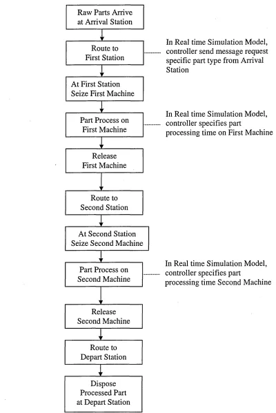
Figure 3.1 Sequences of Events for the 2-Machine Manufacturing System...47
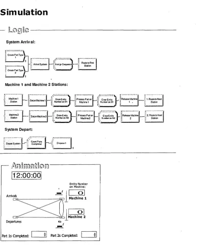
Figure 3.2 Simulation of a 2-Machine Manufacturing System... 48
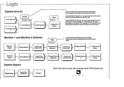
Figure 3.3 Real-Time Simulation of a 2-Machine Manufacturing System... 49
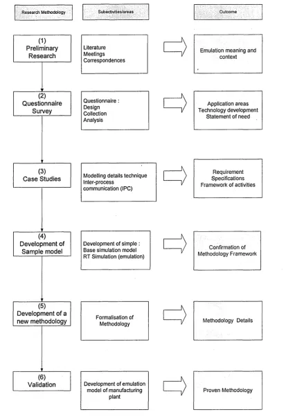
Figure 3.4 Research Methodology Summary... 52
Figure 4.1 The iterative model building process...54
Figure 4.2 Socket Connection... 62
Figure 4.3 OPC Client/Server Relationships... 64
Figure 5.1 Overall Hybrid Simulation-emulation model building flowchart... 78
Figure 5.2 Emulation Model-Controller Integration Flowchart...82
Figure 5.3 Appropriate Level of Detail for Integration...84
Figure 6.1 Arena hierarchical structure... 96
Figure 6.2 A Manufacturing plant layout...97
Figure 6.3 Model Logic for Base Simulation Model... 99
Figure 6.4 Model Logic for Detail Simulation Model...102
Figure 6.5 Animation for Detail Simulation...103
Figure 6.6 Emulation Model Communication Structure... 105
Figure 6.7 Emulation model logic at part arrival station and machining centre 110 Figure 6.8 Message Handling Interface RTCosole... 112
Figure 6.9 Display form for invoking ‘Listen’...113
LIST OF TABLES
Table 2.1 Summary of comparison between simulation and emulation ... 22 Table 3.1 Current and potential areas using of emulation for control system testing. 43 Table 3.2 Present and Future Application Area of Emulation...43 Table 4.1 Comparison of Features for HSEM against Selected Simulation Software.
...71 Table 5.1 Simulation-emulation modelling software features checklist...79 Table 5.2 Summary of Steps of HSEM Modelling... 90 Table 6.1 Simulation-emulation modelling software features checklist for Arena 94
Arena RT... Table 6.3 Panels used in development of HSEM... Table 7.1 Summary of Contributions to Knowledge
115
CHAPTER 1
INTRODUCTION
1.1 Manufacturing System Development
Manufacturing is changing rapidly around the world. The processes, equipment, and systems used to design and produce everything from automobiles to computer chips are undergoing dramatic changes in response to new customer needs, competitive challenges, and emerging technologies. Advances in information systems, business practices, engineering techniques, and manufacturing science now enable companies to produce new and better products more quickly and at a much lower cost than ever before.
As a result, fundamental changes are occurring in the manufacturing environment. This can be seen in the current trend towards highly automated systems that are intended to adapt quickly to change while providing extensibility through a modular, distributed design. It has also placed the whole manufacturing system development process greater importance than ever before.
1.2 Issues on Manufacturing System Development
and Delivery
In order to realise the flexibility and/or productivity that these advanced system promise, system modelling and control are viewed as vital to enable the components of these automated manufacturing systems to work together in an integrated way.
The complexity of such system imposes the need to trace products throughout the system, and include more rules and logic. Thus not only the manufacturing system design has to be efficient, the validation has to be fast and cost effective.
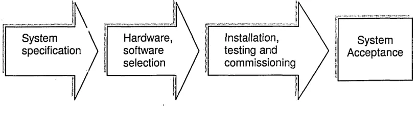
[image:15.615.111.521.203.314.2]To understand the validation process let us look at the manufacturing system development project which generally goes through several key stages as shown in Figure 1.1.
System
specification softwareHardware, selection
Installation, testing and commissioning
System Acceptance
Figure 1.1 Stages for Manufacturing System Delivery
The first stage is definition and analysis, in which simulation has long been used to help determine the system specification. A well-written simulation model can be a valuable tool in the design, analysis, and operation of manufacturing and other complex systems.
The second stage is the selection of hardware and software suppliers, and the construction of the hardware. Key parts of the solution may be tested off-site, in order to verify the technology.
The third stage is on site installation, testing and commissioning. Once testing is finished, the owner takes possession of the installation and the system is ramped up. During this phase, and at any time during the working life of the installation, control system modifications may be necessary as the load on the system changes.
Commissioning covers the period of hardware installation and software testing, as well as acceptance and handoff of the project. In many cases, commissioning disrupts
existing production, and in all cases the sooner the system is successfully commissioned, the sooner the system can be used to generate revenue.
Testing the control system is an important part of the commissioning phase, and yet it is often done under extremely difficult conditions due to the following reasons: • Some of the hardware may already be in use for production.
• Complete testing is impossible before the installation is complete. • “Full system” control tests are often impossible.
• Control tests often conflict with hardware calibration and testing. • Realistic current and future loading levels are unavailable for testing. • Control software may be incomplete.
• Malfunctions may be hard to replicate.
• Modifications may be rushed and not fully tested before implementation.
The commissioning period of a project is often extended, resulting in penalties and the need to bring unbudgeted resources to the site to resolve the situation. This costs both hardware vendors and client's time and money.
Users of industrial simulation products have long requested a way to eliminate the need to reproduce the logic built into the simulation model when the experimentation and analysis phase is complete and the control system has to be developed.
1
.3
Emulation: Simulation Model for Control System
Testing
A growing application of simulation and communication is emulation, where a simulation model is used to replace a real Automated System in order to test and debug an industrial control system. Since an emulation model is designed to provide the same responses as the physical system, it can reliably replace the physical system for many control system tests.
Emulation and control system testing can be carried out as soon as the control system software has been developed, before commissioning. This leaves the critical commissioning window available for unavoidable hardware tests and minimises the set of control system tests that must be done during the final testing stage.
This allows control system designers to test the control logic using the simulation prior to going into the field, which can resuit in considerable savings in terms of time spent on site performing routine logic testing and debugging as illustrated in Figure 1.2.
Typical Project Phases
System Design
Hardware Procurement
On-site Installation
Control Logic Testing and Debugging
Project Phase
System Design
[image:17.616.117.507.234.553.2]3S Using Emulation
| Hardware Procurement
On-site Installation
Control Logic Testing and Debugging
£$£$
A d d itional P rofit
T im e
Figure 1.2 Time and cost benefits of emulation
Emulation provides a reliable and safe way of verifying control code functionality offline, training operators in a safe environment, and of testing modifications to a control system before they get put into effect. Furthermore, the emulation model serves as a test bed for any further control system modifications throughout the life of
the system, so production is not disrupted. Being a software solution, it is easier to implement and modify than hardwired panels. It can also be stored for reuse on a future project and provides the possibility of early testing.
Another advantage of emulation model is that it can be maintained for the lifetime of the automated system it represents. During the productive phase of the system, any proposed changes can be tested on the model before they are implemented on the shop floor, just as the original design was tested. This can save money and provide greater returns from the system, because it can be adapted to keep pace with business changes. The updated model can also be used for training employees about changes to the system, as well.
1
.4
Developing Hybrid Simulation-emulation model
Even though the benefits of using emulation for the analysis of manufacturing control systems are well acknowledged, the speed and cost of the model building remains a concern.
At present, development of an emulation model has to be done independently from simulation model. In other words, a project will require a simulation model for initial analysis and development as well as a separate emulation model for testing a control system. The main reasons for requiring the two-stage development are that an emulation model is often more detailed than a simulation and also emulation model must include communication logic.
Even so, the development of separate software logic for all levels of detail would cause duplication of effort which renders it not cost effective and also creates difficulty in maintaining consistency.
A proposed solution is to develop a methodology to build hybrid simulation- emulation model or composable simulation model, one that is used for both purposes
and should have a facility to switch off/on certain elements from the model as necessary. The present work investigates this possibility and proposes a system approach towards its development.
1
.5
Summary
This chapter has introduced the role of discrete event simulation in manufacturing system development. The importance of efficient validation of manufacturing system design is highlighted. Emulation model, a new form of simulation model developed for early validation of control system is introduced. The chapter ends with underlining the aim of the present research which is to develop a rapid development approach for emulation model building.
The outline for proceeding chapters is as below.
Chapter 2 reviews in more detail the previous works related to emulation and outlays the aims and objectives of the present research.
Chapter 3 describes the justification of the research and the research methodology employed in this research.
Chapter 4 gives the requirement specification for simulation-emulation model building.
Chapter 5 describes the proposed simulation to emulation model conversion methodology.
Chapter 6 describes the validation of the methodology.
Chapter 7 concludes with the findings of the research and propose recommendation for future work.
CHAPTER 2
LITERATURE REVIEW
2.1 Introduction
The previous chapter has introduced the concept of emulation modelling and its benefits. Special emphasis has been drawn towards the need to build the emulation model more cost effective. This chapter presents a background of emulation technology in more detail based on case studies of some emulation-related manufacturing projects.
It begins with defining the scope of investigation for the proposed research. This is followed by a review on the use of simulation in a-variety of applications in manufacturing industry. The next section looks at Discrete Event Simulation (DES), the most widely used type of simulation in manufacturing, particularly in the design and testing of the manufacturing system. The discussion is then directed towards a new form of DES called emulation and its role in control system testing, which become the focus of this thesis. This section is followed by comparative study between simulation and emulation model. It also reports the investigation on the current applications of emulation models in manufacturing industry and the approaches that the models were developed in order to establish the specific requirements for building emulation model from simulation model. The chapter concludes by summarising the findings of the case studies.
2.2 Scope of investigation
Initial literature search has indicated that the term 'emulation' has also been used in a variety of application area and context. For example it is also used in the computer gaming community, software (programming) emulators as well as electronic hardware emulators. However, to avoid ambiguity and to maintain consistency in the context of the proposed research the term 'emulation' was referred to as a new form of discrete event simulation being used to model the plant in manufacturing system design and validation.
From the initial search it was also realised that literature on 'emulation' particularly in regard to its model building was very limited. Consequently, the search was broadened to include the use of the phrases 'simulation for control system testing' 'real time simulation', as well as ' flexibility of adding details' which to some extent considered related to the context of the proposed research.
'Simulation for control system testing' relates to the purpose of emulation in this research context (Habchi and Berchet 2003; Shnits et al. 2004) . 'Real time simulation' provides the understanding of the technology concerning real time communication from emulation(Dougall 1998; Jeong and Kim 1998; Julia and Valette 2000; Stewart et al. 2003). And, ' flexibility of adding details' relates to the multi-resolution modelling as well as usefulness and credibility of the emulation model (Ball 1998; Persson 2002).
2.3 Simulation Technologies in Manufacturing
In general, manufacturing system design involves making long-term decisions such as facility layout and system capacity/configuration. As such, models are typically created and used for a single design exercise, and model run time is not a significant factor during the simulation process.
Manufacturing system operation, on the other hand, involves making decisions on a much shorter time schedule. The activities include operations planning and scheduling, real-time control, operating policies, and performance analysis As such, the model is generally used (and reused) much more frequently, and simulation run time is a more significant factor in the software/package selection and model design process (Smith 2003).
Modelling of such manufacturing systems can be achieved using a number of tools and techniques. While modelling and analysis are important to help ensure good system performance, the integration and complexity of manufacturing systems often makes purely analytic tools difficult to use. Hence, simulation remains one of the most widely used tools to fill this need.
One of the most quoted description of simulation, (Banks 1998) defined simulation as "the imitation of the operation of a real-world process or system over time. Simulation involves the generation of an artificial history of the system, and the observation of that artificial history to draw inferences concerning the operating characteristics of the real system that is represented".
Or put another way, simulation is the technique of a building a model of a real or proposed system so that the behaviour of the system under specific conditions may be studied. One of the key powers of simulation is the ability to model the behaviour of a system as time progresses.
Various simulation technologies and software for manufacturing are available and selection is normally based on the application area and purpose of study apart from the monetary and time constraints.
Within the scope of manufacturing systems the general application areas of simulation include business process modelling, manufacturing process modelling, supply chain modelling, and process and system visualisation
Focusing more specifically on production systems, there are a large number of application areas and simulation technologies. Some simulation technologies are specific to certain application. For example, human tasks simulation is used for ergonomic studies of work areas and manual tasks. Robotic simulation deals with motion and collision control of industrial robots as well as of-line programming of equipment including industrial robots. Assembly simulation is used as an aid for process planning for assembly operation, accessibility and to investigate assembly feasibility (Banks et al. 2000).
A more generic discrete event simulation is widely used in facility design, material handling system design, manufacturing cell design, and flexible manufacturing system (FMS) design. The activities include buffer sizing, lot sizing, material flow including bottleneck detection, plant layout effects, scheduling evaluations, costs and work in process levels (Holst 2001). A more specific form of discrete event simulation called emulation is used to develop and validate control strategies for automated system like AMHS (automated material handling systems) of which AGVS (automated guided vehicle systems) and ASRS (automated storage and retrieval systems) are examples.
2.3 Discrete Event Simulation
Discrete event simulation is one way of building up models to observe the time based (or dynamic) behaviour of a system. A discrete-event simulation is one in which the
state of a model changes at only a discrete, but possibly random, set of simulated time points. During the experimental phase the models are executed (run over time) in order to generate results. The results can then be used to provide insight into a system and a basis to make decisions on. As for emulation, due to the fact that it involves interaction with controller which operates in discrete manner, it is imperative that Discrete Event Simulation is taken as the foundation for its model building. Thus it is essential to understand basic concepts of discrete event simulation.
2.3.1 Key Elements of Discrete-Event Simulation Software
The process of building simulation models will invariably involve some form of software. The software could either be a high level programming language or a data driven software system in which the model is specified using user-defined and default data items. Hence the model is either the software itself or held within a host software system. With the development of more user-friendly simulation systems it is generally the user who will build the model, not an expert.
Inside the software or model will be a number of important concepts, namely entities and logic statements. Entities are the tangible elements found in the real world, e.g. for manufacturing these could be machines or trucks. The entities may be either temporary (e.g. parts that pass through the model) or permanent (e.g. machines that remain in the model). The concepts of temporary and permanent are useful aids to understand the overall objectives of using simulation, usually to observe the behaviour of the temporary entities passing through the permanent ones.
Logical relationships link the different entities together, e.g. that a machine entity will process a part entity. The logical relationships are the key part of the simulation model; they define the overall behaviour of the model. Each logical statement (e.g. "start machine if parts are waiting") is simple but the quantity and variety and the fact that they are widely dispersed throughout the model give rise to the complexity.
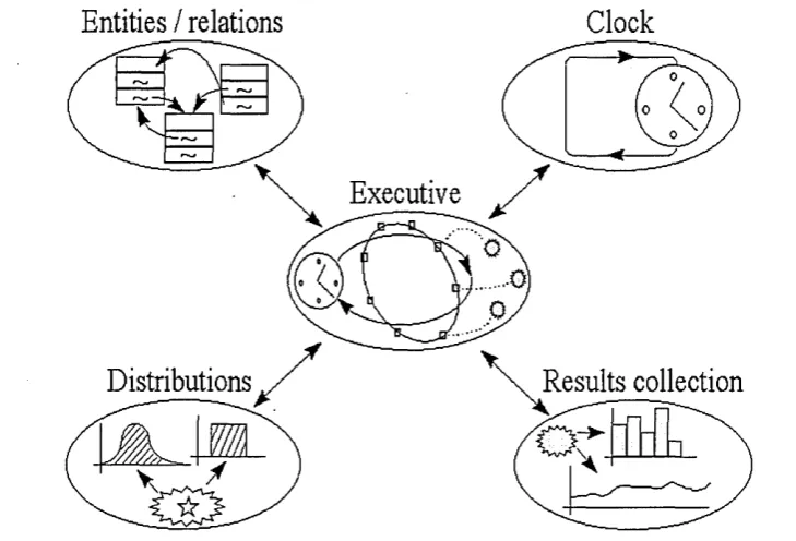
Another key part of any simulation system is the simulation executive. The executive is responsible for controlling the time advance. A central clock is used to keep track of time. The executive will control the logical relationships between the entities and advance the clock to the new time. The process is illustrated in Figure 2.1. The simulation executive is central to providing the dynamic, time based behaviour of the model. Whilst the clock and executive are key parts of a simulation system they are very easy to implement and are extremely simple in behaviour.
Two other elements that are vital to any simulation system are the random number generators and the results collation and analysis. The random number generators are used to provide stochastic behaviour typical of the real world. For example, machine scrap rates will rarely be fixed but will vary between certain ranges hence the scrap rate of a machine should be determined by a random distribution.
The results collation and display provides the user a means of utilising the simulation tool to provide meaningful analysis of the new or proposed system. Simulation tools will typically display tabulated raw results and possess some graphing capabilities.
Entities / relations
Clock
Executive
[image:25.615.120.485.409.657.2]Distributions
Results collection
Figure 2.1 Structure of a simulation system (Ball 1996)
Today, there are hundreds of commercially available DES software packages; some based on the Simulation Programming Languages (SPL) , some on general programming languages, and yet others on proprietary SPLs; some are 2-D, others come in 3-D, and a few offer both; and they range in price from a few hundred pounds to tens of thousands of pounds.
These simulation packages can be further classified into general-purpose simulation packages and application-oriented simulation packages (Law and Mccomas 1999), meaning that they differ in their area of application, from very general (such as Extend and Simul8) to highly specialized packages for various manufacturing applications (such as AutoMod and Quest), or call centres (such as Arena's .Contact Center Edition.), just to mention a few. In fact, the level of specialization in manufacturing goes even further, as evidenced by for example automated storage and retrieval system (AS/RS) modules (such as for Quest).
With regards to emulation modelling in the context of manufacturing, a specific discussion on the software requirement is presented in subchapter 4.4
2.3.2 Discrete-Event Simulation and Control System Testing
As been highlighted in the previous section, control system testing using simulation has received considerable attention among the simulation practitioners (Banks 2000). In line with the scope of the present thesis, the discussion is focused towards manufacturing system development.
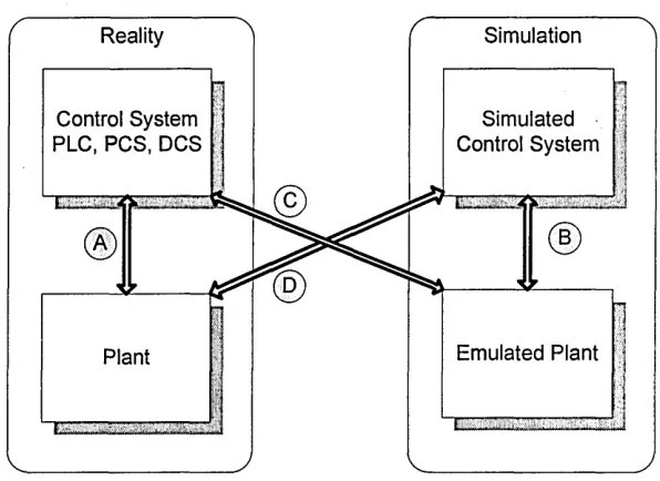
The development of a complex real system which is controlled by a control system may include one or more of the following four design stages or testing types which is illustrated in figure 2.2 (Auinger et al. 1999).
Full prototyping, shown as type A, involves tests with real equipment or system to be controlled and real control systems. This seems the most realistic testing possibility,
although it is quite expensive to build and experiment with the whole prototype system, especially because it involves the risk of failures if the possibilities of its design are not tested thoroughly beforehand.
Full simulation or offline simulation, shown as type B, on the other hand, does not involve so high costs. However, it may disregard some phenomena that are present in the real system or contain additional factors that might influence the outcomes. Among these are the issues arising from the fact that the control architecture is usually distributed across a network of computers and communication requirements among the distributed computing processes are a major concern. It is often difficult to adequately model the communications requirements using software alone. Furthermore, it is often difficult to foresee all potential deadlock situations that can arise and include these within the software simulation of the system.
Simulation Reality
Control System
PLC, PCS, DCS Control SystemSimulated
[image:27.616.149.447.322.539.2]Emulated Plant Plant
Figure 2.2 Possible Combinations between Reality and Simulation for Control System Testing.
(Adapted from (Auinger et al. 1999))
Type C which represents the context of this research emulates the equipment or system to be controlled and uses real control systems. Also called
loop (HIL)-based approach where the inputs and outputs of a controller are connected to a simulation of the part to be controlled (Rabbath et al. 2000). The detailed emulated model is also called emulation (Mueller 2001; Schiess 2001).
Reality in the loop or Real-time control shown as type D uses real equipment and simulates the control systems. This type of testing is also called test bench testing as the equipment to be tested is usually relatively small and easy to set up but the control logic could be complex.
It is important to note that both the development of the real system and the development of the software control system are very expensive. Emulation and real time control have the advantage that they can be carried out in a cheaper way than full prototyping, and stay closer to reality.
Other advantages of emulation as pointed by (Mcgregor 2000) include : (1) Emulation allows earlier, more complete testing.
(2) Emulation allows more time to modify and repair control code. (3) Emulation helps improve client relations.
(4) Emulation facilitates inexpensive, non-disruptive operator training. (5) Emulation provides a safe means of testing system modifications off-line.
However, building an emulation model is still unaffordable for small and medium scale industries, as could be seen from the examples of emulation projects discussed in section 2.5. This is mainly due to its complex nature and as noted in the literature search and also from the discussion with simulation software suppliers and users, that at present an emulation model has to be built independently from simulation model. To find ways of reducing the cost, the characteristics and requirements of emulation model need to be better understood. The next section reviews the similarities and differences between simulation and emulation model.
2.4 Comparisons between Simulation and Emulation
Models
Although a simulation model and an emulation model may look the same, and may be built largely with the same building blocks, there are significant differences in usage as well as their operation. The operational differences include the execution clock, inclusion of hardware, level of detail, system coding, external communication and repeatability.
2.4.1 Different Objectives
Simulation models are used to test and develop different solutions in order to arrive at a better solution, based on an accepted set of pre-defined metrics. It often provides the impartial judge between experience and new ideas, and allows the user to demonstrate functionality and results in a cost-effective and flexible environment. Simulations results help define the physical layout of a system, its operating limits and its control system. Models are used as a basis for extensive experimentation, often using automatic procedures to determine optimal or robust solutions. (Mehrabi et al. 2000)
As the aim of a simulation model is exploratory by nature, the faster it can cover all different possibilities, the better. Simulation modelling software is therefore designed and developed with speed of execution in mind, and the models built with it are also often constructed for fast execution.
(Rohrer and McGregor 2002) argued that emulation models are used in a much more precisely defined way; in order to test the operation of the control system under different system loading conditions, and as a risk-free means of training system operators and maintenance staff. Emulation models are not used for experimentation in the same way that simulation models are; they are unsuited to this function as they often execute only in real time.
The emulation model reflects more precisely the system that will be implemented, and as such, can be used to carry out a constrained series of verification procedures to ensure the performance or reaction of the control system.
2.4.2 Hardware in the loop
A major difference between simulation and emulation is that simulation models are 'stand-alone' done all in software where as emulation models are used in conjunction with hardware, a situation also called hardware in the loop (HIL).
Good system engineering practice would begin with a pure simulation and as components become better defined (with the aid of simulation); they can be fabricated and replaced in the control loop.
For most real systems, there are characteristics that are unknown or too complex to model by pure simulation. Emulation allows hardware to be included in the model and the developers can see the real-time interactions between different hardware and software models. It is also possible to hook up real-world stimulus to peripherals and start debugging system behaviour (Wells et al. 2002).
Industrial communications networks are not deterministic, and control systems need to be designed to run reliably under varying load conditions. It therefore becomes important that emulation models be robust, like the control systems that drive industrial processes and Automated Material Handling Systems (AMHS) (Mcgregor
2002).
2.4.3 Execution clock
(Davis et al. 1996) regarded the primary difference between simulation and emulation arises with the manner in which the model is executed. A simulation model
maintains its own simulation clock. When a decision is taken within the model, the simulation clock does not advance until the necessary calculations have been performed and the decision has been evaluated. This means that simulation time stops • whilst decisions are taken.
As an example consider a box on a diverging conveyor belt. In a simulation model, the box may be sent one way or the other depending on the contents of the box and its final destination. In reality, this decision may be the result of several steps, each of which takes a measurable amount of time. The box may be scanned, and a bar code read. The information may be sent via a network and used to search a database to identify the contents and the destination of the box. Then a control system may verify that a diverter is in the correct position. If it is not, then a pneumatic or electric movement takes place. The initial bar code scan will have taken place before the diverter, at a sufficient distance to ensure that the response can be calculated and the diverter moved to the appropriate position before the box arrives (Mcgregor 2002).
In essence, to be realistic an emulation model must run at exactly the same speed as the control system. Since control systems are designed to operate in real time, and so emulation experiments should be operated in real time.
Thus, the difference between an emulation and simulation in terms of execution clock may simply be summarised by saying that under a simulation, message processing procedures control the advancement of time while under an emulation, the advancement of time is controlled by a real-time clock.
The difference between logical-time simulations and real-time simulations is also apparent in their code. Logical-time simulations have the classical discrete event or continuous simulation data structures and algorithms. Real-time simulations resemble real-time systems - their execution is measured by hertz frequency, and they are typically interrupt driven (Page and Smith 1998).
While real time simulation and emulation has similar characteristics in terms of the execution clock, they are quite different in other aspects of modelling. One of the main differences is with regard to the modelling different levels of detail as explained in the next section.
2.4.4 Level of detail
To use an appropriate level of detail is one of the cornerstones of a valid model. Since the model is, by definition, an abstraction of the actual system under study, not all details are depicted in the model (Ball 1998). Choosing the appropriate level of detail seems to be a balancing act between, minimising the details on the one hand and, adding details to ensure usefulness of the model on the other hand. When reducing the level of detail, the model looses its ability to provide a useful result at some point.
An emulation model is often more detailed than a simulation model. Because the emulation model must provide the same responses to the controllers as real system hardware, the model must be designed to respond to many system events that would otherwise not require custom processing during a simulation.
Therefore the level of abstraction necessary to create the emulation should be as low as possible. For example, an emulation model might be required to send signals to a controller server when a load begins a pop-up transfer, when the transfer has completed lifting, when the load moves to the new section and when the transfer completes lowering (Mcgregor 2002).
To model every component of the system at the low level of abstraction would be inefficient as well as problematic. Models with a high level of detail or resolution describe the real system more accurately, but a simulation in a high resolution requires a long execution time. In large models with high resolution this can lead to an execution which is slower than in real time.
One way to overcome this would be through the use of parallel computing systems. Another alternative which would be much faster is to have the major part of the simulation realised on a rough level and only small parts are simulated in a high resolution hence the use of multi-resolution modelling.
2.4.5 Control system coding
A simulation model may contain control logic developed in the simulation environment that directly controls devices and loads throughout the execution of the model. An emulation model often responds to signals from the external control system, which controls system processes.
(Mcgregor 2002) argued that in order for an emulation model to operate in a way that reflects the reality of an automated system, it must be possible for the modeller to separate the physical parts of the model from the logical or operational parts. Also, in order for the modeller to experiment with the final model it may be necessary to have a part of the model operate under simulation logic, whilst other parts are under the direct control of an external control system.
(LeBaron and K.Thompson 1998) acknowledged that the main benefit of emulation is that it eliminates the need to re-implement code. Code developed and refined in traditional simulation models must be re-implemented into the actual control software if it is to be used. This creates the possibility of communication and re implementation errors. With emulation, the actual control system is used, thus the code is developed and refined as the model is developed thus provides greater confidence in the results.
2.4.6 Inter-process communication (IPC)
Inter-process communication (IPC) is a capability supported by some operating systems that allows one process to communicate with another process. The processes
can be running on the same computer or on different computers connected through a network. IPC enables one application to control another application, and for several applications to share the same data without interfering with one another.
Off-line or full simulation often does not require IPC for the reason that it does not require communication with external application.
Emulation on the other hand must include communication logic to link the model to real time control system which consists of a continuous dialogue between sensors, control systems, and actuators. For example, in an AGV order assignment the location of each AGV is required, the driving distances or times form each location to each location should be available and the actual status of each other handlers should be available. This information is sent from different controllers such as the ASRS manager, the crane manager or the AGV manager to the external algorithm.
As such, development and use of appropriate interface between multiple real controllers and emulation model is crucial in obtaining the correct results.
2.4.7 Repeatable runs
Two or more model runs will always execute in exactly the same way and produce precisely the same results if no parameters are changed between runs. Any impression of randomness in a simulation model is due to the use of pseudorandom numbers to generate certain events such as breakdowns, cycle times and so on. Repeatability is necessary in order to recreate and understand events during the model run, as well as to debug the model as it is built. All events that influence the model execution are contained within the model and are therefore repeatable.
Due to the fact that in most emulation models the control system is separate from the model itself, repeatability is uncertain, as communication events are asynchronous and unpredictable. The model and the control system work with different clocks and
synchronize via a communications layer, itself prone to the decisions of the operating system (Mcgregor 2002).
The comparison between simulation and emulation using the above features is summarised in Table 2.1.
Table 2.1 Summary of comparison between simulation and emulation
Characteristics/features Simulation Emulation
Aim To test and develop
different solutions
To test control system under different conditions
Execution Clock Virtual time Real time
Level of detail Low High
Hardware in the Loop No Yes
Control system coding Control rules hard coded Control rules separated from event code developed and refined as model is developed.
External communication Not always Yes
(interface required)
Repeatable runs Yes
(precisely same result)
No
(communication events asynchronous and unpredictable)
2.5 Applications of Emulation
Over the years emulation modelling has developed steadily from its predecessor (simulation) and has been used in different ways in various environment. While majority of the literature relates the success stories of implementing emulation
[image:35.615.75.536.200.532.2]technology, very few discuss the technical development details of the venture. As such, since emulation is closely related to real time and on-line simulation, some of their applications and development details are also quoted to exemplify the emulation model building.
2.5.1 Automated Material Handling System (AMHS)
Literature search has found that Automated Material Handling System (AMHS) has the most number of applications of emulation. Below are some examples of emulation projects to illustrate the usefulness and benefits of emulation in Automated Material Handling System (AMHS) projects. Included are some technical details on their development and some cautions with regards to emulation model building by the experienced modellers.
Ranistan Conveyor
(LeBaron and K.Thompson 1998) Rapistan Systems, MI, USA and AutoSimulations Inc., UT, U.S.A. used emulation to develop, test, debug, and optimize a complex pick and pack conveyor system for their client. The project integrates a simulation model with the actual control system. The simulation model provides the output for evaluating control logic and algorithms as well as a real time 3-D graphical animation for improved visibility and confidence.
The emulation model they made has a built-in message handler that receives and sends messages through a standard network interface (TCP/IP). The simulation message handler pulls message information from the server at predefined time intervals and acts on these messages. In addition, the simulation model sends messages to the server when certain events have occurred within the simulation model. Emulation has provided them the graphical and statistical output needed to accurately evaluate different algorithms and control logic.
Eskav ASRS
Eskay Corporation (Salt Lake City, UT, USA) an AMHS supplier, developed emulation of a 2-aisle pallet Automated Storage and Retrieval System (AS/RS) Unit Load system to test the order fulfilment control system. The conveyors taking pallets of product to and from the AS/RS were controlled by Think & Do™ industrial control PLC software and the Warehouse Management System (WMS). The simulation model built using Automod was connected to the controller via an OPC server, and to the WMS via sockets.
(Young and Heider 2002) who were involved in the project reported that despite delays created by resource scheduling problems, the emulation was completed months before commissioning was to start. The project manager and software engineers were able to test the full system functionality tested and the checklist over 80% complete before travelling to site
They also attributed that majority of the work for the emulation project involves creating a detailed hardware model and interfacing with the other emulation components. Their work on the interfacing was reduced by using the Automod Model Communication Module (MCM). Nonetheless even though AS/RS, case conveyor, and pallet conveyor are common AutoMod components, for emulation they require significant customization from standard AutoMod operation.
Some important cautions they provided were:
(1) Testing all of the functionality of a MHS would be extremely difficult. It is more important to set limited goals to test and refine basic system functionality.
(2) No amount of software testing can make up for hardware installation difficulties. If the hardware installation is not complete per schedule, the software commissioning will be delayed.
(3) Even if the full system emulation operates correctly, any hardware mistakes will not be revealed until commissioning.
Coca Cola Packer
Coca Cola Enterprise (CCE) Atlanta, GA, USA, needed to accurately model their complex production line and was looking for a method to reduce debugging time on line system start-ups. They developed an emulation model of their Fort Worth Texas production line using Automod software and utilised AutoMod MCM (Model Communication Module) to establish communication between the PLC hardware they use to control their production line and the model (Hodgson and Kartz 2000).
The model was built with a modular structure that supports rapid restructuring to describe different production lines. Photoeye objects, motors, and other resources are modelled in the simulation and the state of these objects are set and read by the PLC connected to the simulation computer using DDE commands provided in the MCM.
By using the model with different speed inputs, different MTTF/MTTR numbers, they made an informed decision that replacing the existing packer with a faster one would not improve the overall line efficiencies after all.
CCE also used emulation to determine the best sequence in which to build a series of ‘layered’ pallets. By using the ‘Dynamic Scheduler’ they were able to show an additional 17% gain in throughput (Cheshire and Hodgson 2001).
General Mlotor Car Assembly
General Motors (GM) used MCM and Automod to do emulation of a GM Holden car assembly plant to validate their After Paint Mix Bank control logic before implementation in the plant. Communication capability was established between AutoMod emulation model and Softlogix 5, an Allen Bradley PLC emulation software using RSlinx, a communication package also from Allen Bradley. The
communication protocol used was Dynamic Data Exchange (DDE) which was provided by AutoSimulations.
In the case where there were more than two models, the Multi Model Synchronization (MMS) Server, an extension of the Model Communications Module was required. The MMS Server automatically opens and manages a connection between each model and the Server and synchronizes all the models that are participating in the simulation.
GM Holden acknowledges that the ability to connect to actual control systems eliminates the need to recreate control logic in simulation models. This not only saves time but also increases model accuracy. GM Holden also realized significant savings using this functionality when their After Paint Mix Bank was fully operational just 3 days after implementation, resulting large financial benefit (Vedapudi 2001)
Schipol Underground Logistic System AGV
(Versteegt and Verbraeck 2002) applied a four-step approach of using simulation in evaluating real-time control systems of Automated Guided Vehicle Systems (AGVS) and Automated Material Handling Systems (AMHS) for the Underground Logistic System (OLS) Schipol in The Netherlands.
The four steps are (1) Testing in a fully simulated environment or offline simulation (Type B in Figure 2.2), (2) Emulation of logistic resources, (3) Combining reality in the loop, emulation and simulation, (4) Implementation of both control and system being controlled in reality.
The strategy in the approach was to solve as many of the technical uncertainties at the first stages and delay the investments in expensive control software and physical logistic resources to later stages. In a fully simulated environment problems can easily and quickly be detected and possible solution can be evaluated for their effectiveness. In later phases the high investments in control software are made, only when the uncertainties and problems are solved. When the uncertainties are solved in
the beginning of the project, the chances of investing in wrong technologies is minimized.
The main idea behind the approach is the development of interchangeable simulated, emulated and prototype components of the control systems and the systems-being controlled. Interchangeable means that components can be changed during experiments without making changes to the control systems.
Some important lessons taken from their work are:
1. The interfaces between the components were defined right at the beginning of the project. Later models and logistic resources had to comply with these interfaces.
2. Use asynchronous messaging to reduce the effect of delays when exchanging information between system components that are coupled in a network.
3. Synchronization between simulation clock and the wall clock is very important aspect in combining simulation, emulation, and prototypes. Except for the software packages that offer standard built-in features for real-time progress in simulation models, separate program has to be made to provide this functionality.
Airport Baggage Handling System
As reported by (Rengelink and Saanen 2002), baggage handling has become one of the major issues in competition between airports. Due to the nature of non-stop operation 24 hours a day, 7 days a week and high security levels, there is a high demand for the quality of the newly implemented systems and its controls at airports. The extensions or changes need to be thoroughly tested in advance without involving the real equipment on site but under conditions comparable to operational conditions.
In view of this, (Rengelink and Saanen 2G02) developed a simulation environment for emulating baggage handling equipment which enabled detailed tests and provided insight into the behaviour of the real PLC for their client.
They used eM-Plant simulation environment due to the following advantages:
1. A large number of basic processes were already depicted within the baggage simulation library.
2. The required details for the emulation were able to be easily implemented because of the Object Oriented structure.
3. This approach saved the manufacturer significant lead time in the project and reduced the required time for testing on-site.
In general, the applications of emulation reported above have indicated that in the long-term, simulation and emulation should be used as an integrated part of the design process, analysis, tests and realization. Optimal use should be made of the activities done during all of the phases and this requires reusability of models, easy adjustability for different lay-outs, and project management based on the developments.
2.5.2 Manufacturing Process Control
queuing network representation of the FMS. Few simulation tools readily permit the modeller to consider the flow of the supporting resources (e.g. tooling, part kits, fixtures, and processing plans).
FMS Emulator
(Davis et al. 1996) argued that the coordination of all entity flows in an FMS is crucial, and it is the interactions among the controllers within the FMS that coordinate these flows. To address these requirements, they introduced the notion of coordinated object, which included an intelligent controller or coordinator to perform integrated on-line planning and control. They developed a coordination architecture called Recursive Object-Oriented Control Hierarchy (ROOCH) for assembling the coordinated objects into a real-time management structure such that planning and control are both distributed and controlled.
To model the performance of the ROOCH, a simulation methodology, the Hierarchical Object-Oriented Programmable Logic Simulator (HOOPLS) was developed. HOOPLS employs an object-oriented architecture, and the C++ programming language was selected for implementing of the simulation model.
To demonstrate the benefits arising from both the ROOCH architecture and the associated HOOPLS modelling paradigm, (Gonzalez and Davis 1997) developed a physical emulator for an FMS in a laboratory environment at University of Illinois at Urban-Champaign, USA. The development of real time control architecture for a physical emulator is described in (Gonzalez and Davis 1998)
TSCS
(Peters et al. 1996) presented a simulation control system developed by the Texas A&M Computer Aided Manufacturing Laboratory (TAMCAM) to explore the advantages and disadvantages of on-line simulation for process control.
The TAMCAM Simulation Control System (TSCS) consists of a simulation-based controller developed in Arena, a message router and client controls developed in Microsoft Visual C++, and an external database system developed in Microsoft Access. The simulation-based controller is built in Arena using the Arena Real-Time template. The Arena model also uses a user-coded dynamic link library (DLL) written in Microsoft Visual C++ to provide the implementation-specific communications functions required by the router. All connections within the real-time system are implemented using the TCP/IP protocols. The connections within the forecast system are implemented with Database Access Objects (DAO).
2.5.3 Other Applications
2.5.3.1 Control Architecture Evaluation
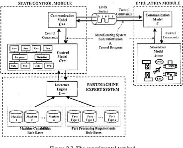
A modular experimental test bed was developed by (Rogers and Brennan 1997; Brennan 2000) to investigate the relative performance of any variety of manufacturing control architectures with any type of manufacturing system. In order to make this analysis possible, the experimental test bed needs to separate the control system from the emulated system allowing each to be developed and tested independently.
Brennan noted that emulated manufacturing system was chosen over a physical system in order to overcome drawbacks of physical systems for this type of experimental work namely difficulty in controlling the test bed and its environment, and difficulty in reproducibility of tests.
The approach to de-couple the manufacturing system and the control system as fully as possible resulted in the basic structure of the modular experimental test bed as shown in Figure 2.3.
STATKi'CONTROI, M ODUI -K EMULATION MODULE
Comm unkat Ion M odel
( >4
-Ccntrol
[image:44.614.116.484.50.347.2]CoTT.tOinJi
| f-ift | P*fi | Pw i | Pi*i |
| ( j r |J t i r r | | |
Control M odel
C+~
UNIX r
S ocket tOHlfOl I ---\C o m n i3 t>J:-i 1o ] i \ ■
ManufattuTijiji System S u te Information
&
Ctinliol Requests;
Inference P A R T /M A C H IN E En-itie | E X P E R T S Y S T E M
C++ M4i3iiiK i MjClitu* I Tjrp*2 Machine Capabilities Rule Bases
Part Processing Requirements R ok Bases
Communication
M uriel
C
Co UK;
C o r.n ia rd i
S im u la tio n
M odel
I ri'tia
&
n
J H
® LJ
Figure 2.3 The experimental test bed (Brennan 2000)
This figure shows the two main modules of the test bed, which can be identified as: (a) an emulation module, which is intended to emulate the behaviour of the manufacturing system being controlled, and
(b) a state/control module, which is used to implement alternative decision-making schemes.
The simulation model was written in Arena simulation package, and can be modelled relatively easily to represent alternative manufacturing system configurations. The Arena simulation model is augmented by a communication model, implemented with additional ANSI C routines, which carries out the low-level communication functions via input/output streams (implemented as UNIX or INET sockets).
The state/control module, which is used to implement the test control architectures, is implemented in the C++ programming language. The structure of this module is similar to the emulation module; it consists of a communication model, used to carry out the low level communication functions, and a control model, used to implement the test control architectures.
A part/machine expert system is included as part of the state/control module to instantiate the control system decision makers. The expert system relies on a set of rule bases that describe the capabilities of the work centres in a given manufacturing system and the detailed processing requirements for the parts that are to be introduced to the system (Brennan and Norrie 2001).
2.5.3.2 Verification of Controller Software
Testing the behaviour of a controller for example a PLC, which, controls a device being part of a more complex system, is usually done by connecting the controller to a ‘stand-alone’ version of the device called ‘mock-up’. This method of verifying and validating the controller’s software is expensive, and test conditions are hard to reproduce. Such tests are incomplete since the interaction of this device with the other parts of the system is simply ignored. Therefore a large part of testing and debugging is still carried out on-site.
To solve such problems (Schludermann et al. 2000) has developed a Soft- Commissioning (SoftCom) , a ‘hardware-in-the-loop’ (HIL)-based system approach that enables interaction between controller such as a PLC and a commercial discrete event simulator, also known as emulator. HIL means that the inputs and outputs of a controller are connected to a simulation (emulation) of the part to be controlled. Hence, the system needs to be modular and scalable.
While most other HIL systems are based on continuous real-time simulation and use fast Digital Signal Processor (DSP), SoftCom was developed to interact with commercial Discrete Event Simulators (DES) and conventional I/O hardware. A
special communication protocol was defined to make flexible SoftCom internal data exchange possible. The two basic modules shown in figure 2.4 are the I/O Devices Driver (IODD), which is used to interface between the I/O hardware and the SoftCom protocol, and the Simulator to real World Interface (SWI) which is used to link the simulator to the SoftCom system.
IODD
PLC
Simulator
SWI
Figure 2.4 The SoftCom System
The IODD internal link to the I/O cards is defined by a library interface, e. g. a Dynamically Linked Library (DLL) in the Windows world. The implementation of this interface depends on the I/O hardware in use. Thus the IODD must support connections to more than one library at the same time to be able to establish links to different I/O cards.
The implementation of the SWI depends on the simulator’s approach of providing access to its variables and objects. (Schludermann et al. 2000) prototype was based on the simulation environment Arena. Arena provides two mechanisms for external programs to interact with the simulation, Visual Basic for Applications (VBA) module and Dynamically Linked Library (DLL) interface. DLL interface was chosen as the link between the SWI and the simulator for the reason for that the DLL can be implement in C++, which provides more flexibility in programming.
The DLL interface defines routines to interact with the simulation: One type gives access to simulator variables and the event calendar. The other type enables the
simulation to execute user cod