ISSN Online: 2331-4249 ISSN Print: 2331-4222
DOI: 10.4236/wjet.2017.54061 Nov. 23, 2017 730 World Journal of Engineering and Technology
Research on Lightweight Design of Automobile
Lower Arm Based on Carbon Fiber Materials
Zengfeng Song, Xiaoyu Zhao
School of Automotive Engineering, Shanghai University of Engineering Science, Shanghai, China
Abstract
Based on the principle of lightweight design, a method of using carbon fiber reinforced composite instead of traditional metal materials to design automo-bile carrier can be proposed. The method uses the equal stiffness design prin-ciple of the composite material parts to lay out the design of the carbon fiber parts, including the application of the laying angle and the thickness of the laying layer in design. Through the analysis of the actual working conditions of the lower arm, the stress and boundary conditions are obtained. After the design of the stiffness, the geometrical topology of the lower arm is further optimized. Finally, the lower arm of the carbon fiber not only met the per-formance requirements, but also to a certain extent, achieved the purpose of lightweight.
Keywords
Carbon Fiber Reinforced Composites, Equal Stiffness Design, Layered Design, Lightweight
1. Introduction
As the energy crisis continues to expand globally, fossil fuels are declining, glob-al temperatures are rising, air quglob-ality is getting worse, so energy saving and emission reduction is the subject of today’s era. Data show that every 10% re-duction in car weight, can reduce fuel consumption by 5%, or even reduce the fuel consumption to 20% [1]. Therefore, the development of lightweight cars has become the mainstream in the car manufacturers: Not only for fuel vehicles, but also for new energy vehicles.
Now the method of vehicle lightweight is mainly from three aspects, one is to optimize the design of the body structure and optimize the size of the various parts of the car to achieve the purpose of lightweight; the second is to use of lightweight materials, such as alloy, plastic, fiber reinforced composite materials,
How to cite this paper: Song, Z.F. and Zhao, X.Y. (2017) Research on Lightweight Design of Automobile Lower Arm Based on Carbon Fiber Materials. World Journal of Engineering and Technology, 5, 730-742.
https://doi.org/10.4236/wjet.2017.54061 Received: August 13, 2017
Accepted: November 20, 2017 Published: November 23, 2017 Copyright © 2017 by authors and Scientific Research Publishing Inc. This work is licensed under the Creative Commons Attribution International License (CC BY 4.0).
DOI: 10.4236/wjet.2017.54061 731 World Journal of Engineering and Technology
etc. [2]. The characteristic of such materials is light and of high strength; starting from material replacement has become the mainstream method of lightweight car; the third method is to optimize the manufacturing process; through the manufacturing process, the purpose of lightweight can be achieved [3]. As the structure has been difficult to further improve the weight of parts and manufac-turing process optimization also requires long-term practice to explore, the lightweight design from the material has become the mainstream direction.
Among the many lightweight materials, carbon fiber reinforced composites (CFRP) [4] have a high specific strength, high specific modulus characteristics. For its excellent design, carbon fiber reinforced composites have been widely used in the field of lightweight. Carbon fiber is also called graphite fiber, the or-ganic precursor fiber made up of carbon fiber; after 2000˚C - 3000˚C graphitiza-tion, the fiber material is obtained. The carbon content is up to 99%, so the elas-tic modulus has been greatly improved [5]. It is not only light and of high strength, but particularly good in rigidity and dimensional stability; it has been widely used in aerospace, such as manufacture satellite antenna, solar cell ma-trix, the aircraft horizontal tail and vertical stability wing box structure [6]. Be-cause of its relatively high price, the application of it is small in the car manu-facturers, but in some auto parts it has also been widely used, such as car wheels, interior parts, roof cover and other components.
As an important part of connecting the wheel and the body, the suspension arm can directly affect the vehicle ride comfort and handling stability [7]. One end of the suspension lower arm is connected to the knuckle; the other end is connected to the frame to transmit the dynamic load of the wheel to the frame and suspension system [8]. Therefore, it is very important to ensure the strength of the part in the lightweight design. The design of the carbon fiber lower arm is not a simple material replacement. Based on the principle of equal stiffness de-sign, the method and process of carbon fiber laying are discussed systematically and arm structure is further optimized.
This article utilizes the principle of equal stiffness design, using composite materials instead of metal materials to achieve the purpose of lightweight, and the model is further optimized. Finally, the carbon fiber swing arm not only meets the strength requirement, but also reduces the weight of 46.8% heavier than the steel swing arm, which is 34.5% lower than that of the aluminum alloy arm. Through replacing the materials of lower arm, the purpose of light weight is achieved.
2. Analysis of Working Condition of Lower Arm
DOI: 10.4236/wjet.2017.54061 732 World Journal of Engineering and Technology
According to the typical working conditions of automobile driving, the force model of automobile suspension system is simplified as brake impact condition, vertical vibration impact condition and turning force condition. On the basis of it, the force analysis of the suspension arm was analyzed, and the force of the lower arm in the three typical ultimate working conditions was obtained when the vertical force is the largest, the lateral force is the largest, and the braking force is the largest. The maximum direction force of the lower arm is taken as the force analysis model.
2.1. Vertical Force Maximum Working Conditions
Because the car in the uneven road driving is conducted, the vertical force of the role of lateral and longitudinal force are relatively small, ignoring its impact, as-suming lateral force Y=0, longitudinal force X =0.
The calculation of the parameters is used in a compact car; the full load is 1425 kg, full load front axle allowable load is 760 kg, full load rear axle allowable load is 665 kg, and the tire type is 205/55 R 16. According to the relationship between the static stiffness and the inflation pressure of the radial tire [10], the static stiffness of the tire is 1.6; considering the relationship between the allowa-ble load and the static stiffness of the wheel, the dynamic load factor of the wheel is 2.5; by the triangular method, the arm of the maximum vertical force can be calculated:
max 1 9375 N
z
F =KG = (2.1)
max 2358 N
gy z
a
F F
c
= × = (2.2)
K—wheel dynamic load factor; G1—front wheel static load; a—wheel and
frame distance (take here 197 mm); c—swing arm from the frame distance
(take here 670 mm).
2.2. Lateral Force Maximum Working Conditions
In this case, because the longitudinal force of the vehicle is small, the influence of the longitudinal force is ignored, so the longitudinal force X =0, the
adhe-sion coefficient of good asphalt or concrete pavement is generally 0.7 - 1.0 [11], where the adhesion coefficient with ϕ=0.8, wheel and frame distance
197 mm
a= , wheel ground distance from the frame b=830 mm, swing arm
from the frame distance c=670 mm, pendulum ball pin fixed point distance
from the wheel vertical line e=20 mm. Because the force of the tire is
trans-mitted through the knuckle to the pendulum ball pin fixed point of the lower arm, the balance of the force and the moment is established by isolating the tire and the knuckle in the calculation. Finally, the direction of the lower arm under the turning condition is obtained:
max 1 7500 N
z
F′ =G′= (2.3)
max max 6000 N
y z
F′ = ×
ϕ
F′ = (2.4)1 5228 N
zy
b e
F G
c
ϕ −
DOI: 10.4236/wjet.2017.54061 733 World Journal of Engineering and Technology
1
G′-Front axle static load.
2.3. Maximum Braking Force Conditions
As the vehicle emergency braking side force is very small, ignoring its lateral force, lateral force is 0. Due to the brake of a great inertia, the center of mass will move at any time, so the calculation of the load transfer coefficient is 1.6 [10] [11], as with case 2, the road surface adhesion coefficient is taken as 0.8. Because most of the cars use wheel brakes, the longitudinal force acting on the knuckle by the suspension causes the total torque of the center of the wheel to be offset against the torque of the center of the wheel by the ground braking force, set the wheel radius as r, determines the distance between the ball hinge and the
ground b and c, the equilibrium equation is established, and finally the force
of the lower arm X is obtained:
max 1 5250 N
z
F′ =mG = (2.6)
max 4200 N
t z
F =ϕ ′F = (2.7)
1 5046 N
zx
b e F mG
c
ϕ −
′ = = (2.8)
3. The Establish of Swing Arm Model
3.1. The Establish of Three-Dimensional Model
The model used in this paper is a typical McPherson suspension arm whose geometry is A-shaped. After measuring the size of the actual swing arm model, the model is simplified and the principle is:
1) Ignoring the impact of non-bearing structure on the model, such as casting lace;
2) Ignoring the arm shape and performance of the structure of little impact, such as only used to reduce the swing arm mass of the hole structure;
3) As only using the swing arm for static analysis, so ignore the swing arm of the process structure, to use of the original swing arm model [12].
After the simplification and processing of the model, the final use of the swing arm CAD analysis model (Figure 1) as shown below:
3.2. Meshing and Boundary Conditions
DOI: 10.4236/wjet.2017.54061 734 World Journal of Engineering and Technology
Figure 1. Three-dimensional model of suspension lower arm.
Figure 2. Swing arm of the grid model.
This paper considers three kinds of extreme motion conditions of the suspen-sion, which is the maximum working condition of the vertical force, the maxi-mum working condition of the lateral force and the maximaxi-mum working condi-tion of the braking force. When the car drives the potholes uneven road, the suspension of the vertical force is huge, swing arm force mainly concentrated in the point C, so that when the vertical force is maximum, the concentration force is applied at the point C, fixed three translational degrees of freedom and two degrees of freedom of rotation of the point A and B, making it can only rotate around the axis of AB, at the same time in order to simulate the shock absorber spring imposed by the constraints, fixed the degree of freedom of the D point in the Z direction. When the braking force is maximum, swing arm along the X
axis are took the maximum force, and the force of the point of action is C, the two points of A, B do not move any, so fixed two points of A, B all degrees of freedom. D point due to the role of the shock absorber, only fixed the degree of freedom of translation along the X axis. When the vehicle turns, swing arm along the Y axis are took the maximum force, fixed two points of A、B all degrees
[image:5.595.267.482.252.424.2]DOI: 10.4236/wjet.2017.54061 735 World Journal of Engineering and Technology
4. Equal Stiffness Design of the Swing Arm
4.1. Extraction of Stiffness Coefficient of Metal Arm
According to the above analysis of the working condition and the treatment of the model, the stiffness coefficient of the arm and the arm of the aluminum alloy is first extracted. The displacement of the swing arm under the working condi-tions is the stiffness coefficient of the swing arm, which is used as the arm of the carbon fiber design basis.
[image:6.595.215.533.288.593.2]Using the above material parameters (Table 1), after the OptiStruct analysis, the displacement of the steel swing arm and the aluminum alloy arm under the three working conditions is obtained. According to the displacement cloud, the maximum displacement of the swing arm under each working condition is ana-lyzed (Figure 3 and Figure 4), which represents the steel and aluminum alloy arm stiffness coefficient. The result of the analysis is in Table 2.
Figure 3. The displacement of the steel arm in the vertical force, lateral force and braking force.
Table 1. Performance parameters of steel and aluminum alloy swing arm.
Material Weight (kg) Density (kg/m3) Modulus Young’s Yield Strength (MPa)
[image:6.595.208.540.656.730.2]DOI: 10.4236/wjet.2017.54061 736 World Journal of Engineering and Technology
[image:7.595.210.540.439.509.2]Figure 4. The displacement of the aluminum alloy arm in the vertical force, lateral force and braking force
Table 2. Stiffness coefficient of metal swing arm.
Types
Conditions force maximum Vertical force maximum Lateral braking force Maximum Steel 0.0072 0.0099 0.019 Aluminum alloy 0.021 0.029 0.056
4.2. Design of Carbon Fiber Swing Arm
4.2.1. Material Parameter Analysis and Model Extraction
Carbon fiber composite material consists of matrix and reinforcement, so that its modulus of elasticity includes the elastic modulus Em of the matrix material
and the elastic modulus Ef of the reinforcement material, the mechanics
pa-rameters of the single-layer plate can be calculated by the composite material mechanics [14].
Longitudinal elastic modulus E1: E1=E vf1 f +Em
(
1−vf)
(4.1)Transverse elastic modulus E2:
(
)
2 2
2 1
f m
m f f f
E E E
E v E v
=
+ − (4.2)
Poisson’s ratio v1, v2: 2
2 1
1
E
v v
E
DOI: 10.4236/wjet.2017.54061 737 World Journal of Engineering and Technology
In-plane shear elastic modulus G12: 12
(
)
1 f m
m f f f
G G G
G v G v
=
+ − (4.4)
The type of reinforcement used in this paper is carbon fiber (T300), The ma-trix is epoxy (5208) [15], their respective volume scores are vf =0.7, vm=0.3.
The mechanical parameters of T300/5208 monolayer are calculated as follows:
1 181 GPa
E = , E2=10.3 GPa, v12=0.28 , G12=7.71 GPa , G13=7.17 GPa ,
23 4.185 GPa
G = .
In order to facilitate the design analysis of the carbon fiber swing arm, the original CAD model is extracted and then meshed, because the carbon fiber swing arm connection point is still connected by metal bolts, so in the connec-tion points are constrained by RBE2 rigid elements.
4.2.2. Swing Pendulum Design
According to the principle of composite design, the main direction of the ma-terial laying must be consistent with the maximum load, so as to maximize the role and performance of the carbon fiber swing arm, the load on the material as shown in Table 3.
This paper intends to use the composite layer of super-layer to lay the way, the super-layer is the meaning of a fixed number of single layer as a layer of consid-eration. From the previous principles of paving, we can see that the same angle of the laying cannot be laid more than four layers, so the two layers of laying an-gle cannot be the same, otherwise the same anan-gle will be more than four layers. And from the table we can see that the 0˚ angle is about 1.5 times by the 45˚ an-gle of the laying, according to the principle of composite paving, 90˚ anan-gle of the laying cannot be less than 10% of the total layer, and in order to change the to-lerance properties of the material, at least set one 45/90/−45 of the layer, so as to to ensure the continuity of the outer layer of the laminate [16].
[image:8.595.209.538.638.725.2]Based on the above analysis, this paper uses the test method for laying design. According to Niu Chunyun (michael C.Y. Niu) [17] datas: The thickness of the unidirectional composite material is between 0.127 mm and 0.191 mm. The thickness of the fabric is between 0.25 and 0.381 mm. This paper intends to use fabric for laying design, selecting the upper limit of the fabric thicknessis 0.381mm that for the single layer of sheet thickness, temporarily a super layer contains 4 single layers, the thickness is 1.524 mm. According to the above con-ditions in the proportion of the load and the principle of laying, the initial test for the layer is [0/45/90/−45/0/45/0/45/0/90/0/−45/90/0], if it meets the stiffness
Table 3. Effect of load on materials.
Conditions The impact on the material
Corresponding to the
laying angle Load size
Size ratio (with a minimum
load of 1) Vertical force effect Pull pressure 0˚ 2358 N 1 The effect of braking force Cut ±45˚ 5046 N 2.2
DOI: 10.4236/wjet.2017.54061 738 World Journal of Engineering and Technology
requirements, it is optimized for its thickness. After analysis, the stiffness coeffi-cient of the test layer (Table 4) is as follows.
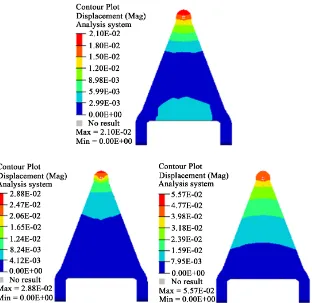
Through the analysis of the stiffness of the swing arm of three different mate-rials, it can be found that the displacement of the carbon fiber swing arm is much larger than that of the steel swing arm and the aluminum alloy arm in the vertical working condition and the braking condition [18]. According to the constant stiffness design principle, the stiffness of carbon fiber swing arm failed to meet the requirements, so it needs carbon fiber swing arm laying optimization design, based on the original laying layer thickness, from the newly defined set of paving angles: [0/45/90/−45/0/45/0/45/0/90/0/−45/90/0]s, the result of the analysis is in (Figure 5).
[image:9.595.209.539.309.616.2]From the results of the optimization, we can see that the carbon fiber swing arm in the vertical force under the maximum working conditions and braking conditions greatly reduced displacement, the stiffness of the arm with the arm of considerable arms, and steel swing arm is also very close, so the optimized car-
Figure 5. The displacement cloud of carbon fiber swing arm, respectively, in the vertical force, lateral force and braking force.
Table 4. Stiffness coefficient of test bench.
DOI: 10.4236/wjet.2017.54061 739 World Journal of Engineering and Technology
bon fiber swing arm stiffness value has been in line with the design require-ments.
5. Strength Analysis and Optimization of Carbon Fiber Arm
5.1. Strength Analysis of Swing Arm
In general, the composites are laminated structures. When the laminates are de-stroyed, the monolayers are usually destroyed one by one. Therefore, it is very important to analyze the stress of the single layer, based on the stiffness of the single plate, strength analysis of tensor (E. M. Wu) theory [19]. Calculate the stiffness of the positive axis using the offset stiffness:
2 2 1 2 2 2 2 2 12 2 2 x y xy
m n mn
n m mn
mn mn m n
σ σ σ σ τ τ = − − − (5.1)
Among them m=cos ,θ n=sinθ, θ is the offset angle of each single layer;
Cai-Wu (E.M. Wu) Tensor theory:
2 2 2
11 1 2 12 1 2 22 2 66 12 1 1 2 2 1
F
σ
+ Fσ σ
+Fσ
+Fτ
+Fσ
+Fσ
< (5.2)Among them: 1 11 2 22 66 2
1 1 1 1 1 1 1
, , , ,
t c t c t c t c
F F F F F
X X X X Y Y Y Y S
= − = = − = =
12
1 1
2 t c t c
F
X X Y Y
= − (5.3)
, , , ,
t c t c
X X Y Y S is the basic strength parameter of the orthotropic monolayer,
and the parameters can be found in the material manual.
After analysis, it can be seen that under the three conditions, the maximum stress layer of the carbon fiber swing arm appears under the maximum working condition of the braking force, and the maximum stress layer appears on the 4th, 12th, 16th and 24th layers respectively (Figure 6), the offset angle of the four layers θ = −45.
Put this four-layer off-axis stress σ =x 74.4 MPa,
σ
y=3.34 MPa, 4.24 MPaxy
τ
= and the strength of the parameters into the formula is:(
2 2)
62 6 3
0.44 34.63 6.72 34.63 43.11 101.6 43.11 10
216.2 35.52 10 20.93 43.11 10 0.81 1,
−
− −
× − × × + × ×
− × × + × × = <
so the strength of the laminate meets the requirements.
5.2. Optimization of Carbon Fiber Swing Arm
5.2.1. Optimization of the Thickness of the Swing Arm
DOI: 10.4236/wjet.2017.54061 740 World Journal of Engineering and Technology
layers, it contains at least one single layer, in the thickness optimization setting, the initial value is 1, the minimum thickness is 0.381 mm, the maximum thick-ness is 1.524 mm, every time it moves a distance to 0.381 mm [10].
From the analysis (Figure 7), in the case of the same conditions, the opti-mized thickness of the value is 38.78 mm, the laying thickness is reduced by 5 mm, it reduced the use of the material.
5.2.2. Geometric Topology Optimization of Swing Arm
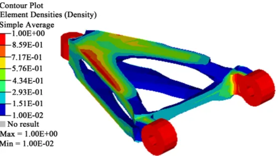
[image:11.595.282.469.338.499.2]Through the analysis of the three working conditions of the carbon fiber swing arm, the stiffness of the carbon fiber swing arm under various working condi-tions can be obtained. Taking the stiffness as the constraint condition and the minimum volume as the optimization target, the mass density as the design va-riable, it optimized the swing arm. The topology optimization is optimized by 18 iterations. By analyzing the density distribution of the iterative step material, the unwanted material is removed and the quality of the components is lighter. Ma-terial density approaching 0 places can be reduced. The maMa-terials with a density of 1 tend to be reinforced, the optimized model is in Figure 8.
Figure 6. Maximum force of single layer plate under braking force.
[image:11.595.280.471.535.707.2]DOI: 10.4236/wjet.2017.54061 741 World Journal of Engineering and Technology
Figure 8. Remove the material model.
6. Conclusion
On the basis of the traditional metal arm, the three-dimensional model of the swing arm is established and the geometric processing is carried out. Based on the principle of equal stiffness design, the pendulum angle and the thickness of the pendulum are designed. On the basis of satisfying the design requirements, the carbon fiber swing arm has further thickness optimization and geometric topology optimization. Finally, the carbon fiber swing arm not only meets the strength requirement, but also reduces the weight of 46.8% than the steel swing arm, which is 34.5% lower than that of the aluminum alloy arm. Through re-placing the materials of lower arm, the purpose of light weight is achieved.
References
[1] Wang, B.L. (2000) Research and Development of Aluminum Body. Research on Automobile Industry, 6, 31-33.
[2] Zhao, M.G. (2010) Wang Chengming. Application and Development Trend of Au-tomobile Lightweight Technology. Henan Electric Engineering Society of the Se-venth Scientific Research Symposium Proceedings.
[3] Wang, H.Y. and Chen, J.Y. (2009) Car Body Lightweight Structure and Light Ma-terial. Peking University Press, Beijing.
[4] Yang, Y.B. (2013) Study on Rigid Strength Design Method of Cylindrical Helical Spring with Carbon Fiber Composites. Tsinghua University, Beijing.
[5] Hu, X.J. (2009) Application of Carbon Fiber in Automobile. City Vehicles, 5, 44-45. [6] Tang, J.M. (2012) High Performance Fibers and Composites. Chemical Industry
Press, Beijing.
[7] Kim, J., Lei, L.P., Hwang, S.M., et al. (2002) Manufacture of an Automobile Lower arm by Hydrofoming. International Journal of Machine Tools and Manufacture, 42, 69-78.https://doi.org/10.1016/S0890-6955(01)00087-6
[8] Ma, M.T. and Yi, H.L. (2009) On Car Lightweight. Chinese Engineering Science, 9, 20-27.
[9] Zhou, C.C. (2011) Design of Ride Comfort and Suspension System. Machinery In-dustry Press, Beijing, 65-72.
Bei-DOI: 10.4236/wjet.2017.54061 742 World Journal of Engineering and Technology jing.
[11] Yu, Z. (2009) Vehicle Theory. Machinery Industry Press.
[12] Zhu, B. (1998) Principle and Application of Finite Element Method. 2nd Edition, China Water Conservancy and Electric Power Press, Beijing.
[13] Wang, Y. (2012) HyperMesh HyperView Application Skills and Advanced Exam-ples. Machinery Industry Press, Beijing.
[14] Riley, W.B. and George, A.R. (2002) Design, Analysis and Testing of a Formula SAE Car Chassis. Motorsports Engineering Conference & Exhibition, 382-399.
[15] Shi, D. (2008) Composites Standard Manual. China Standard Press, Beijing. [16] Yang, N. and Zhang, Y. (2002) Structure Design of Composite Aircraft. Aviation
Industry Press, Beijing, 102-107.
[17] Niu, C. (2010) Composite Airframe Structures. Aviation Industry Press, Beijing, 315-320.
[18] Pan, L. (2006) Design and Development of Typical Body Cover for Carbon Fiber Reinforced Composites. Tongji University, Shanghai.
[19] Chen, L. and Yang, B. (2006) Mechanical Analysis of Composites. China Science and Technology Press, Beijing, 1-2.