On the Comparison of Microstructure Characteristics and
Mechanical Properties of High Chromium White Iron with
the Hadfield Austenitic Manganese Steel
Johnson O. Agunsoye1*, Talabi S. Isaac2, Agbeleye A. Abiona1 1
Department of Metallurgical and Materials Engineering, University of Lagos, Lagos,Nigeria 2
Department of Materials and Metallurgical Engineering, University of Ilorin, Ilorin, Nigeria Email: *jagunsoye@unilag.edu.ng
Received October 7, 2012; revised November 15, 2012; accepted November 27, 2012
ABSTRACT
In this study, high chromium white iron (HC-Wi) alloy and the Hadfield steel were studied. The microstructure of this high-chromium iron was studied using Metallurgical optical microscopy (OM) and compared to the Hadfield steel. The hardness and unnotched charpy impact strength of the HC-Wi alloy and Hadfield steel were examined at ambient tem- perature in the as-cast and heat-treated conditions. A pin-on-disc test at linear speed of 1.18 m/s and a 10 N normal load was employed to evaluate the wear behavior of both steel samples. Microstructural results showed that varying the car-bon level in HC-Wi alloys can affect the chromium carbide morphology and its distribution in the austenite matrix which leads to considerable changes of the mechanical properties. Abrasion test showed that HC-Wi alloys have supe- rior wear resistance, about three times of the Hadfield steel.
Keywords: High Chromium White Iron; Hadfield Steel; Microstructure; Wear
1. Introduction
When there was a challenge to develop steel which pos- sesses two extreme properties at the same time, Sir Ro- bert Hadfield invented Hadfield steel in 1882. The idea was to have steel which is tough and at the same time hard. This type of steel with its austenitic matrix has high toughness, high ductility, and high work-hardability. Majority of the cast Hadfield steel are excellent candi- dates in variety of applications such as: earthmoving, mining, railways, quarrying, dredging and drilling in the oil/gas [1,2].
The global economic recession has continue to place heavy burden on foundries world-wide and Nigeria in particular to look for means of improving their produc- tivity and higher products quality, as well as to strive to achieve the optimum economy in wear industries; in the past decade, the use of carbon steel ball in dry mill grinding has been replaced with in situ ceramic-steel composite synthesis technique to increase the life of the wear parts. In this technique, hard ceramic forming ele- ments are introduced to the molten steel as an alloying element and a more thermodynamically stable reinforc- ing phase will be formed during solidification by the nu- cleation and growth mechanism in the parent matrix [3].
One of the most common ceramic reinforcing materials being used in iron base alloys is carbides and among them chromium carbide due to its high hardness of about 1020 - 1835 Hv [4], have proved to be a unique choice to wear resistance of cast high chromium white iron with martensitic microstructure [5,6]. However, less attention has been paid to the research on Hardfield Austenitic Manganese steel.
In general terms, the high chromium iron suitable for wear resisting applications fall within the compositional limits bounded by the austenitic phase field of the ternary liquidus surface of the iron, chromium, carbon diagram. Solidification takes place by a eutectic process The pro- ducts of the eutectic reaction are austenite and chromium rich carbides of the (FeCr7)C3. For high chromium white
iron with a Cr concentration of some 18 - 20 wt% (hypoeutectic composition), solidification starts with the nucleation of dendritic primary austenite (γ), followed by the formation of γ + M7C3 carbide and its morphology
have been well documented by several researchers [7]. The HC-Wi alloy has an austenitic matrix structure at ambient temperature with chromium carbide dispersed within the matrix. The wear resistance of this material is achieved at the surface when the abrasive particle or im-pact load transforms the unstable Austenite to martensite by strain induced mechanism. This phenomenon of
tenite transformation to martensite causes increased sur-face hardness and less wear rate loss. Carbon content plays a significant role in chromium carbide formation and its morphology as well as hardness, impact tough-ness and wear resistance. In this study, the effect of car-bon content on the microstructure, mechanical proper- ties and wear characteristics of HC-Wi has been studied and compared to the Hadfield steel.
2. Materials
HC-Wi and Hadfield Steel grade of materials were pro- duced in Nigerian Foundries Limited (NFL), Otta, Nige- ria using the charge makeup in Tables 1 and 2 respec- tively. An Electric Induction Furnace of 500 kg neutral lined was used for the melting operation and the sample representative taken from the molten bath at 1550˚C d and poured into a CO2 sand improvised moulds (11 × 11
× 200) mm. The charge makeup used in obtaining the specification is tabulated below.
[image:2.595.58.288.429.569.2]After the first heat from Table 1, a sample representa- tive was taken and casted. For subsequent batches, fine granules of graphite were added in their various compo- sitions of 1.6% C, 2.2% C, 2.7% C and 3.3% C respec- tively to the molten bath and the temperature maintained at 1520˚C - 1543˚C for 10 minutes to enable the graphite granules dissolve adequately. This process was repeated
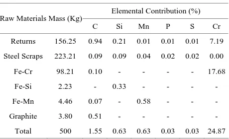
Table 1. Charge makeup for HC-Wi.
Elemental Contribution (%) Raw Materials Mass (Kg)
C Si Mn P S Cr
Returns 156.25 0.94 0.21 0.01 0.01 0.01 7.19
Steel Scraps 223.21 0.09 0.09 0.04 0.02 0.02 0.00
Fe-Cr 98.21 0.10 - - - - 17.68
Fe-Si 2.23 - 0.33 - - - -
Fe-Mn 4.46 0.07 - 0.58 - - -
Graphite 3.80 0.51 - - -
[image:2.595.58.287.597.735.2]Total 500 1.55 0.63 0.63 0.03 0.03 24.87
Table 2. Charge makeup for Hadfield Steel.
Elemental Contribution (%) Charge makeup
for Hadfield SteelRaw Material
Mass
(Kg) C Si Mn P S Cr
Returns 187.83 0.410 0.190 4.760 0.005 - 0.570
Steel Scraps 234.80 0.095 0.120 0.120 - - -
Fe-Cr 7.04 0.001 - - - - 1.280
Fe-Si 2.00 - 0.300 - - - -
Fe-Mn 63.40 0.140 - 9.640 - - -
Graphite 4.93 0.66 - - -
Total 500 1.30 0.610 14.52 0.005 0.000 1.850
for all incremental granules addition. To reduce the ten- dency for oxidation, 1 Kg of Aluminum Briquette was added to the melt. Besides, Hadfield steel melt was pre- pared according to ASTM 128 C standard as presented in
Table 2.
The overall chemical composition obtained for the 2 heats and 5 batches is presented in Table 3.
A calibrated Hilger Analytical Direct Optical Emission Polyvac Spectrometer E980C with 20 analytical channels was used for the analysis of the chemical composition of the HC-Wi and Hadfield steel. Hadfield steel is difficult to machine due to its work-hardening propensity. Hence, a sample representative was taken from the Hadfield steel molten bath and poured into a (10.20 × 10.2 × 200) mm preheated medium carbon steel mould so as to obtain the required (10 × 10 × 50) mm bar for the impact test. This technique was aimed at avoiding the need to ma- chine the samples. To investigate the effect of the heat treatment of Hadfield steel on the properties of HC-Wi, halves of all the specimens with the size (10 × 10 × 50) mm were solution annealed at 1050˚C for 30 minutes and then water quenched.
2.1. Microstructure
For microstructural analysis, all the as-cast and heat-treat- ed samples were cut from the bottom end, ground with tehrapol-31, then polished using a colloidal suspension of 0.04 µm silicon dioxide and then etched in 100 ml alco- hol and 3 ml HNO3 acid after polishing using Allegrol
with diamond suspension at the Metallographic Labora- tory, Department of Mechanical Engineering of the Uni- versity of Ottawa, Canada. A metallurgical optical micro- scopy was used to study the microstructures.
2.2. Mechanical Properties
[image:2.595.310.542.638.739.2]Vickers micro hardness of tested samples was measured using Duramin-1 microhardness tester struers. The re- ported hardness values were the average of five meas- urements. Charpy unnotched impact test was also carried out on (10 × 10 × 50) mm standard Hadfield and HC-Wi specimens at room temperature. In order to compare the wear resistance of the developed HC-Wi alloys with Hadfield steel, abrasive wear tests were conducted on all
Table 3. Chemical composition of the HC-Wi.
Material C Mn Si Cr P S Mo Ni Al Fe
HC-Wi-1 1.55 0.63 0.63 24.87 0.03 0.03 0.02 0.01 0.01 Balance
HC-Wi-2 2.22 0.63 0.62 24.60 0.03 0.03 0.01 0.01 0.01 Balance
HC-Wi-3 2.73 0.59 0.60 24.20 0.03 0.03 0.01 0.015 0.02 Balance
HC-Wi-4 3.26 0.56 0.60 23.60 0.03 0.03 0.01 0.01 0.02 Balance
Hadfield
cast sample in the as-cast and heat-treated conditions us- ing a pin-on-disc wear machine as per ASTM G99-95 Standard. The disc used is En-32 steel hardened to 62 HRC, 200 mm track diameter and 12 mm thick with sur- face roughness of 20 µm Ra. The sample with cross sec- tion 10 mm × 10 mm was taken from the fracture impact test and used for the wear test. Applied normal load on all the samples was 10 N over a sliding distance of 70.8 m on a fresh 120 grit SiC abrasive paper. Before and after each test, the sample was carefully cleaned with acetone and weighed using an analytical balance with an accuracy of 0.001 g. The relative wear resistance was given by the weight loss of HC-Wi alloy samples related to the weight loss of the heat-treated Hadfield steel sam- ple. The reported values are the average of four test runs on each composition material.
3. Results and Discussion
3.1. Microstructural Analysis
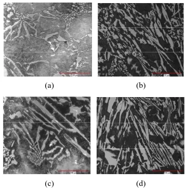
Figures 1(a)-(d) show the effect of carbon content on the morphology and distribution of primary chromium carbides in HC-Wi alloys in the as-cast condition. When the high chromium molten alloy starts to solidify; chro- mium carbide nucleation takes place and grows in the melt and crystallizes as coarse primary chromium carbides between the liquidus and solidus temperatures. It has been observed from the data available from Table 3 and Equation (1),
%Carbide12.33 %C 0.55 %Cr 15.2 (1) [8]
that as the carbon content of the HC-Wi increases, the amount of chromium carbide increases (Table 4) and primary chromium carbides change from the fairly round, strip into spherical shape and they are distributed more uniformly up to carbon content of 2.73 but further in-crease in the carbon content dein-creases the homogeneity of the chromium carbide distribution within the austenitic matrix (Figures 1(b) and 1(c)).
In HC-Wi alloy, due to the presence of >20% Chro- mium in the composition as one of the strongest carbide forming elements in steel compared to iron or manganese (very high affinity of chromium to absorb carbon), chro- mium reacts with the dissolved carbon of the molten steel resulting to the formation of chromium carbide instead of iron manganese carbide.
In as-cast Hadfield steels, austenite grain boundary steel are surrounded by a continuous network of segre- gated and brittle (FeMn)3C shown in Figure 3(a).
Solu-tion annealing between the temperature range of 1000˚C - 1050˚C dissolves these carbides in austenite and subse- quently quenching in water prevents the formation M3C
in grain boundary as shown in Figure3(b) [9].
In high chromium austenite steel, due to the presence
(a) (b)
[image:3.595.332.512.83.266.2](c) (d)
[image:3.595.311.536.329.576.2]Figure 1. Optical micrograph of HC-Wi in the as-cast con- dition. (a) HC-Wi-1 (b) HC-Wi-2 (c) HC-Wi-3 (d) HC-Wi-4.
Table 4. The amount of chromium carbide (Cr3C7, %) in the as-cast conditions.
Sample HC-Wi-1 HC-Wi-2 HC-Wi-3 HC-Wi-4
Volume of Cr7C3 17.59 25.70 31.77 37.98
(a) (b)
[image:3.595.313.534.609.703.2](c) (d)
Figure 2. Optical micrograph of HC-Wi in heat-treated condi-tion. (a) HC-Wi-1 (b) HC-Wi-2 (c) HC-Wi-3 (d) HC-Wi-4.
(a) (b)
of more than 20% chromium, chromium is one of the strongest carbides forming element in steel compared to iron or manganese (chromium has high affinity for car- bon), chromium reacts with the dissolved carbon in the molten steel leading to the formation of a more stable chromium carbides instead of iron manganese carbides. When compared to Figure3, iron manganese carbides in HC-Wi samples virtually non-existence and form a con- tinuous network of brittle phase around the austenite grains.
3.2. Mechanical Properties
Initially measured values of Vickers hardness of all sam- ples in as-cast and heat-treated conditions before the ab-rasion test are presented in Figure 4. It shows that the hardness of HC-Wi alloys is almost 69% higher than Hadfield austenitic manganese steel due to the presence of high percentage of extremely hard chromium carbide Cr3C7 in the microstructure. Solution annealing has less
influence on the hardness changes of HC-Wi alloy com- pared to Hadfield austenitic steel. Hadfield steels contain some segregated hard grain boundary carbide of the form Cr3C7 within the softer austenite matrix. This is clearly
responsible for the increase in overall hardness in the as-cast conditions. Figure4 also showed that austenite matrix in HC-Wi alloys is more than twice the hardness of the Hadfield steel (in both as-cast and heat-treated conditions).
This considerable increase in austenite hardness is re-lated to the solution of carbon and chromium elements in iron lattice coupled with the precipitation of secondary chromium carbide (Figures 1 and 2) in austenite which strengthens the soft matrix.
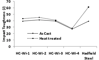
Figure 5 shows Charpy unnotched impact toughness of the materials. The main difference in impact energy values before and after the heat treatment was observed in the Hadfield steel and it is due to the dissolution of the
0 100 200 300 400 500 600
Ha
rd
n
e
ss
(H
v)
As‐cast
Figure 4. Vickers micro-hardness of as-cast and heat-treated materials.
0 10 20 30 40 50 60 70
HC‐Wi‐1 HC‐Wi‐2 HC‐Wi‐3 HC‐Wi‐4 Hadfield
Steel
Im
p
ac
t
To
u
gh
n
e
ss
(J
)
[image:4.595.325.522.86.207.2]As Cast Heat treated
Figure 5. Impact toughness of HC-Wi alloys and Hadfield steel.
brittle carbide, segregated along the austenite grain boundaries in the as-cast condition (Figure3(a)). These brittle phases with lamellar/acicular morphology along the boundaries cause stress to be built-up in the matrix, leading to dislocation pile up, crack initiation, propaga-tion and crack growth and subsequently low impact toughness of the Hadfield steel in as-cast condition. For HC-Wi alloys, chromium carbide morphology and its distribution both influence significantly the impact en- ergy. HC-Wi-1 composition with uniform distribution of chromium carbide has the highest impact toughness, while the HC-Wi-4 has the lowest impact toughness. As the carbon content increases, the morphologies of the chromium carbides in the matrix also change. The dis- tribution of the chromium carbide influences the me- chanical properties of the material.
3.3. Wear Resistance
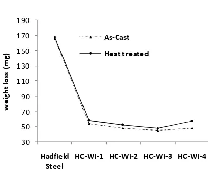
The wear loss of HC-Wi alloys compared to the heat- treated Hadfield steel in the as-cast and heat-treated con- ditions are presented in Figure6. The predominant wear mechanism in the pin-on-disc abrasion test is micro cutt- ing and surface hardness of the materials plays a signifi- cant in determining the wear resistance. Hence, HC-Wi alloys shows remarkable higher wear resistance (3 times) than Hadfield steel due to higher surface hardness caused by the existence of hard carbide phase dispersed within the austenite matrix. Despite the low surface hardness of HC-Wi-3 compared to HC-Wi-4, the wear resistance of HC-Wi-3 is superior and higher than HC-Wi-4 (Figure 6). This is because the carbide distribution in HC-Wi-4 is heterogeneous (Figure 2(d)). Hence, that the distribu-tions of the hard second phase carbide also affect the wear resistance.
4. Conclusions
[image:4.595.92.253.545.709.2]30 50 70 90 110 130 150 170 190
Hadfield
Steel
HC‐Wi‐1 HC‐Wi‐2 HC‐Wi‐3 HC‐Wi‐4
we
ig
h
t
lo
ss
(m
g)
As‐Cast
[image:5.595.69.272.69.238.2]Heat treated
Figure 6. Weight loss of HC-Wi alloys and Hadfield steel.
2) The presence of chromium carbide lowers the im- pact toughness of HC-Wi alloys compared to Hadfield austenitic manganese steel.
3) The mechanical properties of HC-Wi alloys are af- fected by the distribution of the hard second phase parti- cles in the austenite.
4) For practical application where replacements of worn-out mechanical components result to frequent plant shutdown with associated high maintenance cost, the more expensive HC-Wi alloys are recommended over the chea- per Hadfield manganese steel.
REFERENCES
[1] E. Bayraktar, F. A. Khalid and C. Levaillant, “Deforma- tion and Fracture Behaviour of High Manganese Auste- nitic Steel,” Journal of Materials Processing Technology, Vol. 147, No. 2, 2004, pp.145-154.
doi:10.1016/j.jmatprotec.2003.10.007
[2] I. Karaman, H. Sehitoglu, A. J. Beaudoin, Y. Chumlya-kov, H. J. Maier and C. N. Tomé, “Modeling the Defor- mation Behavior of Hadfield Steel Single and Polycrys-
tals Due to Twinning and Slip,” Acta Materialia, Vol. 48, No. 9, 2000, pp. 2031-2047.
doi:10.1016/S1359-6454(00)00051-3
[3] A. K. Srivastava and K. Das, “Microstructural and Me- chanical Characterization of in Situ TiC and (Ti,W)C- Reinforced High Manganese Austenitic Steel Matrix Com- posites,” Materials Science & Engineering: A, Vol. 516, No. 1-2, 2009, pp. 1-6. doi:10.1016/j.msea.2009.04.041 [4] A. Maksim and H. Irina, “Thermophysical Properties and
Thermal Shock Resistance of Chromium Carbide Based Cermets,” Proceedings of the Estonian Academy of Sci-ences, Engineering, Vol. 12, No. 4, 2006, pp. 358-367. [5] W. Shizhong, J. Zhu and L. Xu, “Investigation on Wear
Behaviors of High-Vanadium High-Speed Steel Compar- ed with High-Chromium Cast Iron under Rolling Contact Condition,” Materials Science and Engineering: A, Vol. 434, No. 1-2, 2006, pp. 641-648.
[6] Y. Uematsu, K. Tokaji, K. Nishigaki, D. Okajima and M. Ogasawara, “Effects of HIP and Forging on Fracture Be- haviour in Cast Iron with Spheroidal Vanadium Carbides Dispersed within Martensitic-Matrix Microstructure,” Ma- terials Science and Engineering: A, Vol. 527, No. 10-11, 2010, pp. 2621-2628. doi:10.1016/j.msea.2010.01.067 [7] J. O. Agunsoye, V. S. Aigbodion and O. S. Sanni, “Effect
of Heat Treatment on Microstructure and Mechanical Properties of NF6357A Cast Alloy for Wear Resistance Application,” Journal of Minerals and Materials Characteri- zation and Engineering, Vol. 10, No. 11, 2011, pp. 1077- 1086.
[8] J.-P. Breyer and W. Gisèle, “Metallurgy of High Chro-mium-Molybdenum White Iron and Steel Rolls,” In: R. B. Corbett, Ed., Rolls for the Metalworking Industries, Wa- rendale, Pittsburgh, 2002, pp. 29-40.