344
©IJRASET: All Rights are Reserved
Aircraft Localization Algorithm for Multilateration
System using Hyperbolic Localizations with S & AC
Mode
Miss Shruti Sharma1, Laxmikant Dewangan2
1
M.Tech. Scholar, 2Asst. Prof. ECE Department, Chouksey Engineering College Bilaspur (CG)
Abstract: Multilateration is a shown development that has been being utilized for quite a while. It was delivered for military purposes to decisively discover Aircraft, which is portrayed by TDOA (time qualification of arriving) of a banner gotten by different sensors. Multilateration uses different ground stations, which are placed in crucial regions around an air terminal, its neighborhood terminal locale or a more broad area that covers the greater incorporating airspace. This paper is centered around Aircraft localizataion calculation for multilateration framework utilizing hyperbolic limitations with S and AC mode. We evaluated TOA from mode S and mode A/C flag and changed over them into TDOA. Given limitation calculation tends to exact position of the objective .The scientific conditions of this strategy, is presented. Moreover, the gave hyperbolic restriction technique performs superior to Chan and Taylor arrangement strategy. For this unique circumstance, a few reenactments are performed. Blunder estimations are additionally done where we connected AWGN clamor. In this paper, the hyperbolic localizations performance analysis done by GDOP (Geometric dilution of precision), HDOP (Horizontal dilution of precision) and MSE. These execution examination parameters are computed for every technique .Finally, the outcomes are looked at and affirmed that they gave hyperbolic limitation strategies precision is better.
Keywords: S Mode, AC Mode, Cross Corellation., Multilateration(MLAT), Time of arrival(TOA),Time difference of arrival (TDOA), Localization, Air traffic control(ATC), Geometric dilution of precision(GDOP) ,Horizontal dilution of precision(HDOP).
I. INTRODUCTION
Multilateration (MLAT) is an observation strategy in light of the estimation of the distinction in separation to two stations at known areas by communicate signals at known occasions. Not at all like estimations of outright separation or edge, estimating the distinction in remove between two stations results in a boundless number of areas that fulfill the estimation. At the point when these conceivable areas are plotted, they shape a hyperbolic bend. To find the correct area along that bend, multilateration depends on numerous estimations: a second estimation taken to an alternate combine of stations will deliver a second bend, which converges with the first. At the point when the two bends are thought about, few conceivable areas are uncovered, creating a "fix".
Multilateration is a typical method in radio route frameworks, where it is known as hyperbolic route. These frameworks are generally simple to develop as there is no requirement for a typical clock, and the distinction in the flag timing can be estimated obviously utilizing an oscilloscope. This shaped the premise of various broadly utilized route frameworks beginning in World War II with the British Gee framework and a few comparable frameworks presented throughout the following couple of decades. The presentation of the chip enormously streamlined task, significantly expanding ubiquity amid the 1980s. The most mainstream hyperbolic route framework was LORAN-C, which was utilized far and wide until the point that the framework was closed down in 2010. Different frameworks keep on being utilized, however the far reaching utilization of satellite route frameworks like GPS have made these frameworks to a great extent excess.
are utilized, different hyperbolas are framed, and the crossing point of the arrangement of hyperbolas 1 2 gives the PL gauge of the source. The hyperbolic position area method offers the upsides of not requiring extra equipment or programming inside the versatile unit, capacity to determine ambiguities in the PL assess and limiting the impact of clamor inside the portable radio channel. Numerous associations are creating contending items to conform to the FCC's E-911 order, which requires U.S. cell transporters to give area data of telephone calls, viable October 2001. The exactness required is 100 meters or better. A significant number of these items will execute the previously mentioned time contrast of landing procedure for finding a versatile with fluctuating degrees of precision. Techniques for ascertaining the TDOA and portable position have been explored already [1][2]. A few strategies ascertain the two dimensional position and others the three-dimensional position contingent upon the level of straightforwardness wanted.
II. LITERATUREREVIEW
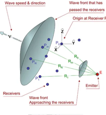
[image:2.612.204.408.249.470.2]Multilateration is generally utilized in common and military applications to precisely find an air ship, vehicle or stationary producer by estimating the "time distinction of entry" (TDOA) of a flag from the producer at least three synchronized beneficiary locales (reconnaissance application) or the signs from at least three synchronized producers at one collector area (route application). [1-4]
Fig. 2.1. TDOA geometry.
Multilateration system, commonly known as hyperbolic positioning system, during World War I the first localization applications based on hyperbolic positioning principle introduced which was called Hyperbolic Audio location System. This was based on the relative time of measurements of sound signals. This kind of system was used for determining the hidden war cannons location in the battlefield.
Fig. 2.2 The first hyperbolic positioning system: “Hyperbolic Audio Location System”.
In figure 1.2, that system, the time of arrivals, of the sounds of explosions, to the receiving stations A, B, C were determined by using a chronograph installed in the computer center. After that, these measurements were used to manually determine how far the canon from the station was B in respect to station A and how far from the station C in respect to station B. Finally, user could draw two hyperbolas ( - and - in figure 2.1), whose intersection was taken as the cannon location.
[image:2.612.179.432.550.642.2]346
©IJRASET: All Rights are Reserved
Amid the main world time frame, the rise of common business flying felt the need of precise position of air ships in regard of takeoff and entry fields. In that period, the improvement of the guides for air navigation.[5-9]
MLAT application gives a wellspring of air terminal reconnaissance data for more secure and more productive ground development administration at airplane terminals. Applicable air terminal ground vehicles should be prepared and shown, together with flying machine, on a circumstance show. MLAT underpins ground struggle identification by giving successive updates of air ship positions. The MLAT framework utilized by various associations as business and general aeronautics, Military Aviation.[10] Multilateration System is turning into an imperative reconnaissance and distinguishing proof framework for substantial air terminals. The benefits of MLAT over regular SSR (Secondary observation radar) is that, it is modest to introduce and keep up. It is more exact than others are and it works better, where other regular radar has issue with its expansive rotatings.[11-12] Multilateration framework is comprises of a number recieving wires and these reception apparatuses getting a flag from an air ship and a focal handling unit ascertains the airplanes position from the time contrast of landing (TDOA) of the flag at the distinctive radio wires. Numerically, TDOA between two radio wires compares, with a hyperboloid in three-dimensional on which the air ship is finding. At the point when four radio wires distinguish the air ships flag, at that point we can assess the flying machines three-dimensional area by the crossing points of coming about hyperbolas. At the point when three reception apparatuses are accessible, a 3D position can't be assessed straightforwardly, however in the event that the objective height is known from other source (like-Mode C) at that point the objective can be found. This is really alluded as a 2D arrangement. With in excess of four recieving wires, at that point additional data can be utilized .Verifying the rightness of alternate estimations or ascertaining a normal position from all estimations, which ought to have a general little error.[13-18]
III.METHODOLOGY
Here we present an comparative study and analysis about chain, taylor and hyperbolic with our proposed approach.
A. Chan method
It is a non-iterative answer for the hyperbolic position estimation issue. This technique is fit for accomplishing ideal execution for discretionary sensor. This strategy is proposed by Chan. This arrangement is shut frame, which is substantial for inaccessible and close sources. This technique performs better when TDOA estimation blunders are little. It gives express arrangement shape. In Taylor arrangement strategy express arrangement shape isn't accessible. It is likewise superior to Taylor arrangement technique. This Chan strategy can exploit excess estimations like the Taylor Series technique.
B. Taylor Series method
The Taylor-arrangement strategy linearizes the conditions by utilizing Taylor-arrangement extension. It utilizes an iterative strategy to explain the arrangement of direct conditions. It begins with an underlying supposition and enhances the gauge at each progression of emphasis by deciding the neighborhood slightest square arrangement. Taylor arrangement can give us precise outcomes. It likewise make utilization of repetitive estimations, which will enhance the position area arrangement. In spite of the fact that, it requires a decent beginning theory which can be computationally serious. Be that as it may, the vast majority of the instances of linearization of the non-straight conditions does not present the undue mistakes in position area estimation.
C. Hyperbolic location estimator with equations
For getting exact position of a source, it requires a proficient hyperbolic area estimation calculation. For that hyperbolic area calculation, TDOA is essential. These TDOA will be in charge of hyperbolic bends and the hyperbolic bends will be in charge of creating an exact and unambiguous answer for position area issue. Our gave calculation depends on TDOA estimation. The position area of an objective is resolved from the convergence of hyperbolic bends, which are created from TDOA estimation. The hyperbolic bends conditions are an arrangement of non-liner condition. It is difficult to unravel non-direct condition.
Fig. 3.1 Cross-correlation based TDOA estimation process
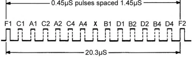
[image:4.612.157.455.258.337.2]2) TDOA Calculation using S Mode: To understand the TOA estimation technique by mode S signal, we need to understand what is mode S and how its wave form generates.
Fig. 3.2 Mode S reply Waveform
The air ship mode S answer comprises of a preface of four heartbeats divided with the goal that they can't be shaped incorrectly from covering mode An or C answers. The rest of the beats contain information, which utilize beat position sufficiency balance. Every one of 1 µs interim is isolated into two sections. On the off chance that 0.5 µs beat possesses the main half and there is no heartbeat in the second half then a twofold 1 is shown. On the off chance that it's contrary way, at that point it speaks to a parallel 0. Truth be told, the information is transmitted twice, the second time is transmitted.[9] This organization is free from blunder because of a confusing answer from another air ship.
The answer of mode S additionally has equality and address in the last is 24 bits.
3) TDOA estimation from mode A/C: Before, write the estimation method of TOA. First, we need to understand the mode A & C waveform and how these are used in aircraft.
Fig. 3.3 Mode A/C reply Wave form
Albeit, 4,096 diverse personality codes are accessible in mode A. Answer may appear to be sufficient, once specific codes have been for crisis cases and the number is fundamentally diminished. In a perfect world, a flying machine keeps a similar code from take off until the point that arrival regardless of whether the air ship cross the global limits, as it is utilized at the airport regulation focus to show the air ships callsign utilizing a procedure, which is known as code/Callsign transformation. In this way, a similar mode A code ought not be given to in excess of one air ship in the meantime as the controller on the ground could be given the wrong callsign with which to speak with the air ship.
[image:4.612.153.461.503.601.2]348
©IJRASET: All Rights are Reserved
ship whether flying machine are moving out of their relegated flight level. A slight difference in a couple of feet could cross the edge and be shown as the coming addition up and 100 feet changes. Littler augmentations were attractive.
So as indicated by our proposed approach here we will figure TDOA utilizing S mode and AC mode and after that we will apply hyperbolic limitation calculation.
D. Comparative Simulation Analysis Process:
Basically, in this method one transmitter and four receiver is used. And at first, the position for receiver and transmitter has been set. Based on that, got one position for transmitter and four receiver. Now, after setting the positions for receivers and transmitter, have to apply following process for calculation of TDOA and TOA.
1) S MODE 2) AC Mode
So as per our proposed approach we will caluclate TAO using S Mode and AC mode and after the calculation of TOA we will calculate TDOA and than we will add AWGN noise with TOA. Additive white Gaussian noise (AWGN) is a basic noise model, which is used in information theory to mimic the effect of many random processes that occur in nature. Additive is because it is added to any noise, which might be intrinsic to the information system. . And after getting noisy TOA, we can easily get the noisy TDOA. Which will get by the difference of TOA2 –TOA1.Like this. We got TOA for transmitter and receiver by using cross correlation approach.
To get an accurate position location estimation of a source requires an efficient hyperbolic position location algorithm. When the TDOA information is obtained, the hyperbolic PL location algorithm will be responsible for producing an accurate and clear solution to the position location problem.
IV.RESULTANDANALYSIS
In this research for performance analysis of the algorithms, we calculate GDOP, HDOP, SNR, MSE. For better understanding, we will describe these parameters first and discuss the calculation method.
A. GDOP
Geometric dilution of precision (GDOP) describes error which is caused by the relative position of the receivers. are spread apart . If the baseline is larger than the distance between target and receiver then the accuracy is higher.
1) GDOP Calculation: According to Hyperbolic Localization Method, we can calculate GDOP from the following equation,
GDOP=
∈ , 4.1
Where, ∈ is the range error variance. ∈ is the TDOA Variance.
B. HDOP
Horizontal dilution of precision (HDOP) is the measurement of the geometric quality of a GPS satellite configuration in the sky. The relative accuracy of a horizontal position of the GPS satellite is determined by HDOP. The smaller the DOP number, the better the geometry.
1) HDOP Calculation: For calculation of HDOP we use this equation.
HDOP= + , 4.2
Where, = = .
C. MSE
1) MSE calculation: For calculating MSE we take the difference of original and estimated location and divide with the total number of size.
For MSE calculation, we use the following equation,
MSE = E[(x−x^) + (y−y^) ] , 4.3
Where (x,y) is the co-ordinate of the source and (x^,y^) is the coordinate if the estimated position of the source.
changes. We know when error less, MSE less and SNR is higher. And higher SNR result means accuracy high. So we can see from the table that in proposed hyperbolic S mode method the SNR value is higher comparing to other four methods. Overall shows that, the position accuracies of two algorithm (Chan and Taylor) are very similar. And, solving hyperbolic non-liner equations is not easy. Taylor LS algorithm is much more inefficient than Chan because it is iterative where Chan algorithm gives close solution is. Nevertheless, Chan algorithm performs well only when the reference base station is at the origin (0, 0), otherwise very large location errors are calculated.
From the accuracy percentage we can say that in hyperbolic S mode accuracy is very high, than AC mode , Cross Correlation, Chan and then Taylor series method. Although, Taylor series method can give an accurate position estimation at reasonable noise levels.
TABLE I
Dilution of Precision Rating table according to its value Dilution of Precision Value Rating Accordingly
<1 Ideal
1-2 Excellent
2-5 Good
5-10 Moderate
10-20 Fair
20> Poor
TABLEII SNRCOMPARATIVE TABLE
Parameters Chan Taylor
SNR VS MSE Chan= Upto 17.1 Snr Taylor= Upto 18.64 Snr Hyper_Cross=Upto 25.4 Snr Proposed_Hyper_A_C_Mode= Upto 24 Snr
Proposed_Hyper_S_Mode= Upto 27.6 Snr
350
©IJRASET: All Rights are Reserved
TABLEIIII
SCIENTIFIC PARAMETERS PERFORMANCE ANALYSIS TABLE
Parameter Chan Taylor series Hyperbolic_Cros
sCorellation
Proposed Hyperbolic_A_C_Mode
Proposed_Hyperbolic_SMode
Error Difference Range -20 to 22 Km 17 to 17.5 Km 8.6 to 9.1 Km -10 to -25 Km 6.6 to 7.2 Km
MSE Measurement Level Very Low Low Medium High Very High
SNR Up to Up to 28.25
dB
Up to 23 dB Up to 24.55 dB Up to 24 dB Up to 27.8 dB
% Accuracy 96 % 92.6% 97.6% 97.4 % 98%
GDOP Accuracy
Level Medium Accuracy Level Low Accuracy Level High
Accuracy Level High Accuracy Level Very High
HDOP Accuracy
Level Medium Accuracy Level Low Accuracy Level High
Accuracy Level High Accuracy Level Very High
V. CONCLUSION
The precise and effective strategy is accommodated confining a source from an arrangement of hyperbolic Curves characterized by TDOA Cross Corellation Hyperbolic method, Chan, and Taylor series, proposed AC mode Hyperbolic methaod & S Mode Hyperbolic methods result simulated. A comparison with proposed and a=other exsistung approach was developed. The comparison was established in basis of HDOP, GDOP, SNR and Error difference in distance. After using these performance analysis parameters, we found proposed S mode hyperbolic method more efficient and result is more accurate than other two method. Here, we discuss about TOA estimation methods. Cross correlation method and how to estimate TOA and how to convert it into TDOA provided in this paper.
REFERENCES
[1] HARRY B. LEE . Accuracy of Range-Range and Range-Sum Multilateration Systems [J].IEEE Transactions on Aerospace and Electronic Systems, 1975, AES-11(6): 1346-1361
[2] P. Mariano, P. De Marco, M. Pici,A. Carrozzo. ADAM: ADvanced Airport Multilateration System [C]. European Radar Conference, 2004, 289-292
[3] HARRY B. LEE. A Novel Procedure for Assessing the Accuracy of Hyperbolic Multilateration Systems [J]. IEEE Transactions on Aerospace and Electronic Systems, 1975, AES-11(1): 2-15
[4] Y. T. Chm, K. C. Ho. A Simple and Efficient Estimator for Hyperbolic Location [J]. IEEE TRANSACTIONS ON SIGNAL PROCESSING, 1994, 42(8): 1905-1915
[5] HARRY B. LEE . Accuracy Limitations of Hyperbolic Multilateration Systems [J].IEEE Transactions on Aerospace and Electronic Systems, 1975, AES-11(1): 16-29
[6] Carl Evers, VA Rick Cassell, VA Derrick Lee. Analysis of ads-b, asde-3 and multilateration surveillance performance -- nasa atlanta demonstration [C]. AIAA 17th Annual Digital Avionics Systems Conference, 1998
[7] PatrickJ. Martone, M A George E. Tucker. Candidate requirements for multilateration and ads-b systems to serve as alternatives to secondary radar [C]. Digital Avionics Systems, 2001.
[8] Michael R. Owen. Correlation of DME Pulse Trains for Use in Multilateration [C]. Integrated Communications, Navigation and Surveillance Conference, 2007. [9] Gaspare Galati, Maurizio Gasbarra, Emilio G. Piracci. Decoding techniques for SSR Mode S signals in high traffic environment [C]. Radar Conference, 2005. [10] SEONG-TAEK PARK, JANG G WLEE. Design of a Practical Tracking Algorithm with Radar Measurements [J]. IEEE TRANSACTIONS ON AEROSPACE
AND ELECTRONIC SYSTEMS, 1998, 34(4): 1337-1344
[11] Pave1Bezousek, Vladimir Schejhal. Radar Technology in the Czech Republic [C]. Microwaves, Radar and Wireless Communications, 2002
[12] A. Smith, R. Cassell, T. Breen, R. Hulstrom, C. Evers. Methods to provide system-wide ads-b back-up, validation and security [C]. 25th Digital Avionics Systems Conference, 2006
[13] Gaspare Galati, Maurizio Gasbarra, Mauro Leonardi. Multilateration Algorithms for Time ofArrival Estimation and Target Location in Airports [C]. European Radar Conference, 2004.
[14] G. Galati, P. Magarò, E.G. Piracci, L. Ciccotti. Multilateration applied to airport vehicles management systems: the Agile Trasponder [C]. Radar Conference, 2006
[15] M . Loren Wood. Multilateration system development history and performance at dallasift. WORTH AIRPORT* [C]. Digital Avionics Systems Conference, 2000 [16] C. Meier Hoyue la, A.J. Terzuo li, Jr, R.P. Wasky. Determining possible receiver locations for passive radar [J]. IEE Proceedings - Radar, Sonar and Navigation,
2005, 152(3): 206-214
[17] Jeffrey T. Beyer. Enhancements in wide area multilateration processing techniques[C].
[18] Alex Smith, Carl Evers, Rick Cassell. Evaluation of Airport Surface Surveillance Technologies [C]. CIE International Conference of Radar, 1996 [19] M.A. Spirito . Further results on GSM mobile station location [J]. ELECTRONICS LETTERS, 1999, 35(11): 867-869