Abstract — The present article deals with the suggestion of a new software application for the small and medium-sized enterprises, which was developed at the Technical University of Kosice, Faculty of Manufacturing Technologies, with the seat in Presov. The software enables to prepare the manufacturing process plans with multivariant approach and to process the information in several versions. It can be used for optimization according to the selected criteria and creation of technological documentation and NC programs on the basis of hybrid approach, too. The internal mathematical structure was generated and a new code system was suggested for manufacturing objects inside a new software application. Production preparation based on these principles allows a greater flexibility of manufacturing units when searching for the means of effective production processes with required economic results.
Index Terms — Computer Aided Process Planning, manufacturing system, coding, mathematical structure, multi-variant information system
I. INTRODUCTION
VERY product unit that wants to be competitive in present day should be characterized by a suitable combination of required productivity, flexibility, and quality. The experience proves that one of the most toilsome and the most time consuming phases of manufacturing process is the Process planning. It contains many partial tasks of routine character and this fact has a great impact on new product rise time and on the cost reduction expressed in the product price. It also influences economic and time aspects of the manufacturing and accuracy and quality of the part. [8] The routine activities can be used for searching, calculation, e.g. calculation of cutting parameters, determination of standardized time consumption, calculation of the costs for the performance of specific operation, information grouping and searching. The information is often redundant and inaccurate. However, by contrast, processing of obtained information has to be
Manuscript received March 20, 2012; revised April 4, 2012.
This article originates with the direct support of Ministry of Education of Slovak republic by grants KEGA 035TUKE-4/2011 and ITMS num. 26220220155.
Peter Monka was with Technical University of Kosice, Slovakia. He is now vice head of Department of Manufacturing Technologies at Faculty of Manufacturing Technology of Technical University of Kosice, 040 01 Slovak republic (phone: 421-903-353783; fax: 421-51-7581491; e-mail: [email protected]).
Katarina Monkova was with Technical University of Kosice, Slovakia. He is now a lecturer at Faculty of Manufacturing Technology of Technical University of Kosice, 040 01 Slovak republic (e-mail: [email protected]).
implemented on the basis of the exact, predetermined rules and regularities achieved by the exact methods and by the multiyear work during the engineering technology development. These know-how data are arranged by a technologist to the process plan to ensure the most profitable production of the part according to the chosen criteria under specific conditions. At the same time the products have to comply with technical requirements from the view of correct part functionality.
One of the important preconditions to become a successful company in the business is the ability to archive the relevant data for the long time under management quality systems in compliance with ISO standard and according to the requirements specified in particular production conditions. [3] For the newly-established production-business entities it is very important to select a suitable system supporting the use and processing of all information obtained during the entire production process.
For already existing plants, it is needful to install a software product, which is compatible with already existing information structure without a need of an expansive interface – for example between CAD/CAM system and CAPP system. Another criteria for the choosing of the suitable CAPP system or another software application is its flexibility and ability to adapt to the user requirements. For small and middle-sized enterprises the acquisition of integrated CAPP system can be expensive and sometimes even unaffordable investment with the long rate of return period. On the other hand, it is also fundamental for these enterprises to have the manufacturing information saved and used in various forms (for example for the generation of technological information or NC programs) with the possibility of successive completing, editing and modificating of necessary data.
The solution of the problems connected with the data storage, processing, and exploitation within CAPP in the small and medium-sized enterprises can be found in creation of the new software applications. One of them was developed at the Faculty of Manufacturing Technologies of Technical University of Kosice with the seat in Presov. This software uses a multi-variant approach to the preparation of the process plan according to the selected criteria. It enables • the creation of technological documentation and NC
programs on the basis of hybrid approach, • compendious storage of production data, • data processing within short time
and it economizes the manufacturing costs, too.
The system is called Individual Application System (IAS) because of a possibility to accommodate it to the individual requirements of the enterprise.
Individual Application System for Computer
Aided Process Planning
Peter Monka, Katarina Monkova, Member, IAENG
The software input menu is displayed in Fig. 1.
Figure 1 The basic application menu
II. THEORY OF MULTI–VARIANT PROCESS PLANNING The theory of multi-variant process planning deals with the production process (during its project phase and also during the production) as a homogenous unit, which includes technological and labour processes organised via various possible parallel phases so that the final product is processed in the optimized way for the set purposes whilst fulfilling all the demands laid by a consumer. [5]
On the basis of this theory it is useful to create a combination of potentialities of various techniques used in individual process plans based on the strategy aimed at achieving the specific goal of the production unit. The main objectives of this theory are: [9], [10]
• the creation of the unified definition environment for all factors, which directly affect the result of production process,
• the flexible interface which enables bidirectional exchange of the required information with all surrounding systems.
A. Mathematical basis
The objects in machine engineering such as the parts, machines, equipments and others are possible to be modeled at the various stages with various goals. These objects can be regarded as various types of models (physical, simulation, computer, mathematical). Each of these objects may be considered a system which consists of some features or, on the other hand, as a feature being the part of some system. [7]
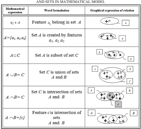
The smallest unit of system model is “feature”, which is in suggested theory indicated by a small cursive letter (with or without index), for example a1, a2, ... aj, ..., an. Features with the same characteristics can be grouped into a set. The set is defined if all of its features have the same specific property. In such case it can be said that the features belong into the set. The sets are indicated by capital letters A1, A2,
..., Ai, ..., An. There are relationships between features and sets, some of them are shown in Table I.
The manufacturing system can be expressed by the relation:
O
S
E
MS
(1) MS - manufacturing systemE - Equipment S - Segment O – Operation.
TABLE I
SOME OF THE RELATIONS BETWEEN FEATURES
AND SETS IN MATHEMATICAL MODEL
Graphical presentation of manufacturing system in set expression is shown in Fig. 2.
Figure 2 Manufacturing system in set expression
On the basis of this structure it is possible to consider the manufacturing system to be a set, which is unification of subsets marked as subsystems.
B. The subsystem “Equipment”
In this theory the term “Equipment” is used for a wide range of various production equipments, such as: premises (the manufacturing halls, workshops, offices, ...), equipments for the energy production and energy distribution, machines, tools, jigs and fixtures, equipments for the manual operations, equipments for assembly, measuring and testing equipments, equipments for storage, other devices (for example computer techniques, ...). The set Equipment can be mathematically expressed as follows:
E = P EP ME MTE TE SE OE (2)
E - Equipment
P - Premises (manufacturing halls, workshops ...)
EP - Equipment for Power production and distribution
ME - Manufacturing Equipment
MTE - Measuring and Testing Equipment
TE - Transport Equipment
SE - Storage Equipment
OE - Other Equipment (e.g. computer techniques ...) All of these sets are the unions of subsets. For example the set ME can be written down as follows:
ME = M
T F AME EMO AE (3)M - Machines
T - Tools
[image:2.595.305.548.71.294.2]AME - Auxiliary Manufacturing Equipment
EMO - Equipments of workshops for Manual Operation
AE - Assembly plants Equipment
In next structuring the subset Machines can be divided according to the technology type as follows:
M = MM CM WM AM MoM (4)
M - set of all Machines in the plant
MM - Machining Machines
CM - Casting Machines
WM - Welding Machines
AM - Assembly Machines
MoM - Moulding Machines
The following features come under the MM subset:
MM = M01 M02 M03 M004 M05 (5)
MM - Machining Machines
MO1 - turning machines
MO2 - milling machines
MO3 - drilling and boring machines
MO4 - machining centre
MO5 - grinding machines
Production plant has a certain number of turning machines, which are the features of the set M01:
MO1 = {m
1, m2, m3, m4, ...} (6) or
n 1 i i 1 Om
M
(7)mi - is i-th machining machine
n - is total number of machining machines in the plant. Individual turning machines are characterized by properties, which define the machine selection for turning of a specific part, for example: the centre lathes are suitable for the machining of too long shafts, for very small parts is necessary to select different, etc. [6] The relationship between turning machines and their properties can be written down by the functional dependency:
MO1 = f (p
1, p2, p3, p4, p5, p6, p7, p8, p9, ...)
MO1 - set of all plant turning machines
pi - i-th property of turning machine
p1 - lathe type
p2 - control system
p3 - tool equipment
p4 - dimensions
p5 - energy and precision
p6 - turret head type
p7 - speeds
p8 - feeds
p9 - postprocessors
If the object examined has more than one substantial property from the view of goal of the task beings solved, then the feature set containing the lathes that are suitable for the turning operation according to selected property can be obtained by partial derivation:
1O1
1 01 M p M (8) concurrently
M
1O1
M
01 , where1 O 1
M - is a set of lathes, which satisfy the request for machine selection according to the specific property.
For example in concrete situation M1O1can be a set of turning machines of the plant, suitable for machining of very
long parts. This set is mathematicized as 1
O 1
M
= {m1, m3, m4, m9, ...}Similarly, other sets MOj1that originate by differentiation of MO1 with respect to j-th property can be obtained
, p M M j 01 1 O j
(9)
simultaneously for every MOj1 holds O1 O1 j M
M .
Each of these subsets MOj1 includes various features mi, consequently individual properties “pj” satisfy on each occasion different turning machines.
Lathes, which meet all the requirements, can be found as intersection of sets
M1O1
M2O1
M3O1
1 O 4
M ... = MoptO1 (10)
1 O opt
M - is a set of turning machines that conform to requests for all selected properties.
Subsequently 3 cases can occur:
1/ MoptO1 is a one-feature set, i.e.: if all conditions are met, it is possible to turn the specific part only on one suitable machine.
2/ Set MoptO1 has several features, i.e. it is necessary to choose another criteria for the selection of machine (for example it is necessary to find out which of the machines is free for the machining in this time).
3/ Set
M
optO1 is empty. In this case it is needed to leave out one of the machine choices according to some properties (nearly always it is the property that influences selection of process at least) or the situation has to be solved differently (e.g. by producing the selected part in alternative plant; by buying a new machine with needed parameters which on the other hand increases the production costs).The principle of this simplified model is applicable not only for lathes or other machines but also for next subsets of Equipment subsystem, and also for subsystems Segment and Operation.
C. The subsystem “Segment”
The basis of subsystem “Segment” is the classification code for the segment description, which represents the start point of the entire system. The suggested coding system keeps the space for creation of process plans not only for cutting technology but also for other technologies. [1]
The codes cover the following characteristics: • geometrical shape,
• class of part,
• manufacturing characteristics, • class of dimensions.
The coding of segment in this software application is based on the assumption that the data registered in this module will be used later at the creation of technological or drawing documentation and the parameters already once defined will be possible to be recorded by another database module.
regard to a large number of parameters variable in consequence of the varied manufacturing process conditions, the most suitable was to use the type of code at which the starting positions are reserved for the characteristic properties of the object. Other positions are attached to the attribute part of code according to the need to define the classification of the object. Definitive version of the generated code with its structure is shown in Fig. 3.
Figure 3 Structure of individual code parts in subsystem Segment
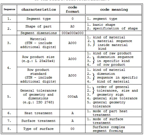
In this code, for example, its 4-th part describes the raw product size. This sequence of code is created by 4 positions. The first position is defined by alphabet letter, which determines the type of raw product (for example the group “A” includes the sheets, steel strips…). The second, third, and fourth position give the standard sequence for specific type of raw product in database module. It is possible for the plant to register up to 1000 standards for one type of raw product. Segment code may appear to be too difficult at the first sight, but its creation is very simple when working with user interface and it is supported by the partially completed databank. A new code is formed by 8 parts. Basic characteristics of all individual parts are shown in Table II.
TABLE II
THE IMPORTANCE OF INDIVIDUAL PARTS
OF THE CODE IN SUBSYSTEM SEGMENT
D. Subsystem “Structure of operation”
The specific machining operation may be specified by means of three stages: [2]
• class of the machining, • type of the machining, • process of the machining.
The example of the Structure of operation coding is shown in Fig. 4, which represents the code meaning. [2]
Figure 4 The example of structure of operation coding
III. DATABASE STRUCTURE DEFINING AND USER INTERFACE SUGGESTION
Computer Aided Process Planning (CAPP) represents the activities leading to preparation of manufacturing documentation and the details of material equipment for the production process. When designing the new product the aim is to secure or increase its technical value not only by systematization of the production process but also by increasing the level of the supporting tools for the rational processing of the manufacturing documentation and data needed for planning. [4]
The database respects a structure of production system, which can be logically divided into the following parts: 1) Product design
a) Design procedures b) Design methods c) Value analysis 2) Manufacturing design
a) Technological structure planning b) Process planning
c) NC programming
3) Studies of labour and production costs a) Work analyses
b) Work measurement c) Wage schemes.
According to the structure given above and according to analysis of requirements of the real (existing) plant involved in the project, the necessary data were arranged by means of “relation database”. The fraction of difficult database tables and their relations used in reality (in the new software application IAS) is shown in Fig. 5.
The following principles were defined step by step inside the database system:
[image:4.595.51.286.469.689.2]Figure 5 Database tables and relations – fraction of the structure used
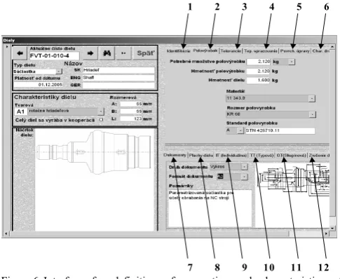
For correct database working it is required to fill in all relevant information to the interface designed for storing properties and characteristics of production segment (see Fig. 6).
1 2 3 4 5 6
[image:5.595.311.537.144.298.2]7 8 9 10 11 12
Figure 6 Interface for definition of properties and characteristics of production segment (part, subassembly … final product)
For the purpose of this information system the term “Segments” indicates also all manufacturing objects such as parts, subassemblies, and assemblies groups to final product. This interface asks for basic information about production segment and further indications: (numbered as per Fig. 6) 1. Identifications of segment by basic information. 2. Raw product identification.
3. Information about prescribed tolerances. 4. Heat treatment information.
5. Surface treatment information. 6. Surface roughness information.
7. Documents (definitions and full electronic form) related to segment of production.
8. Surfaces generating volume of production segment. 9. Indications for individual technology.
10. Indications for technology type. 11. Indications for technology group.
12. Indications for cancellation of production segment. These procedures have to be worked out by operators whose knowledge about advantages and disadvantages of every strategy is used for processing of production segment.
In the framework of this phase it is possible to prepare the classification of this segment for future handling as well as manufacturing conditions.
After entering all relevant information - production segment data and classification – the information system is ready for a definition of manufacturing characteristics as is displayed in the Fig. 7.
1 2 3
4 5 6 7
Figure 7 Interface for definition of manufacturing characteristics
The application interface provides the facility to create several alternatives of process plans (No. 6 in Fig. 7), which are suitable for actual segment production (No.5 in Fig. 7). For example for every hypothetic event that can occur in the future the operator creates a process plan with equivalent strategy, or in case of new unpredictable event the new strategy can be worked out. Basic varieties of prepared process plans can be worked out for the following cases: 1. Maximum efficiency
2. Minimum costs
3. Change of goods flow (in the event of using the full capacity machine tools)
Individual process plans have to be specified and there are more phases defined within each process plan (No.7). Every phase represents a relatively independent line of operations. For example the first phase may be the casting, the second - machining and the last one - surface treatment.
In each work phase the operator may generate individual manufacturing sequences as follows (Fig. 7):
1. manual entry of technological operation cycles (No. 1), 2. as NC program (No.2) – directly entered by the operator
or established for a group of fixtures in the framework of Group Technology or automatically generated within CAD/CAM systems environment
3. in form of the sequence of operation pictograms (No.3) 4. in form of the simulation sequence (video, animation,
sequence of the pictures, …) (No.4)
The really tested Multi-Variant Process Planning system is able to connect wide variety of CAD/CAM systems (models, CL data & NC programs etc.) and various methods of technological approaches for multi-variant process plan design correspondent to requests of the European plants.
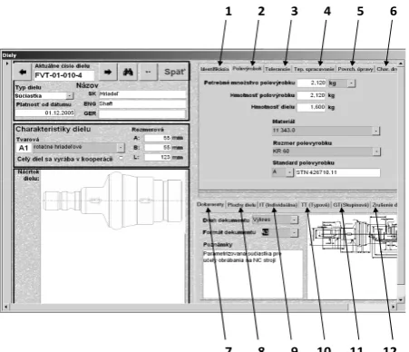
[image:5.595.46.289.285.484.2]1 2 3 4 5 6
[image:6.595.47.273.49.243.2]7 8 9 10 11 12
Figure 8 Interface for definition of properties and characteristics of production segment (part, subassembly … final product) 1- Identifications of segment, 2 - Raw product identification, 3 -Tolerances, 4 - Heat treatment information, 5 - Surface treatment information, 6 - Surface roughness information,7-Document definitions, 8 - Surfaces generating volume of segment, 9 - Individual technology, 10 - Type technology, 11 - Group technology, 12 - Cancelling of production segment
CONCLUSION
From the very beginning of the project activities, prepared IAS served for a suitable analyzing of individual real database objects (components, substructures, structures, finished product), i.e. the new analytical tools were created as required. On the basis of the aforementioned multi-variant theory characteristics a new software application was created and established into the real production conditions, where the computer aided process planning consisted of approximately 6000 components. The manufactured product, in this case, was a result of cooperation between the German company providing investments and additional activities and the Slovak companies providing the technical process planning and the production of a final complex product. This project was very successful and the Slovak companies use the software up today.
The main benefits of the above mentioned software application, elaborated on the basis of the multi-variable process planning in the real manufacturing conditions, can be summarized as follows:
• reduction of the warehouse stock variabilit (at the first application by nearly 30 per cent)
• immediate information about the product elaboration • fast acquisition of the details via interfaces for the wage
records and accounting
• analytical tools enabling the adoption of better decisions • acquisition of the statistical values of parameters
applicable to plan production in the future.
The system tool was created in the way to be easily implemented to already existing information company structure via flexibly adjustable interfaces. It is also user-friendly, developed with the characteristics of GUI, typical for OS MS Windows, so that the basic grasp of its functions does not require expensive trainings. Of course, to make maintenance of this system productive, it has to be familiarized with the given philosophy and possibilities of tactic and strategy planning, through which the production can be optimized.
Presented manufacturing information system is a unique one in cooperation with CAD/CAM systems (practically with every known) and its connectivity to other systems (accounting, stock, wages, etc.). This concept brings following advantages, mainly for micro companies:
• Modular conception.
• Flexible interconnections to partners. • Convenient price level.
The established solution serves the purpose of easier and faster assigning of the process parameters, shortening of the computer aided process planning documentation time in real production conditions, and it also supports the effective utilization of the production plant based on the mathematical model of object variation.
Output system data can be used for processing of the details for the warehouse, economic and wage records as for their control and optimization.
All know-how used in described system shows the new tasks for future research within this scope:
• Investigation of a system for comparing of 3D data for finding of objects similarity.
• Study of graphical features used for process planning • Finding better interfaces for CL data creation, NC
program sharing, alerts about 3D model changing etc. • Seeking certain data formats for communications
between cooperating plants.
• Research for general format of process plan data.
• Investigation of production environs in other European countries.
REFERENCES
[1] Ackerman, J.: Presentation of contribution Integrative Planning of Logistics Structures and Production Plants in Competence Cell-Based Networks, conference Advances in Production Engineering, Warsaw, 2007-06-14
[2] Arn, E.A.: Group technology, Springer Verlag, Berlin, ISBN 3-540-07505-4
[3] Belan, M., Tarasovicova, A.: The utilization procedural gaseous medium in machining of steel 1.4301 by tools from HSS, In: Proceedings of the 22nd International DAAAM Symposium on "Intelligent Manufacturing & Automation: Power of Knowledge and Creativity", 2011, Vienna, Austria
[4] Hloch S. et al.: Using waterjet in reverse logistic operations in discarded munitions processing, In: Technical Gazette. Vol. 18, no. 2, 2011, p. 267-271, ISSN 1330-3651
[5] Sharma V. et al: Multi response optimization of process parameters based on Taguchi—Fuzzy model for coal cutting by water jet technology, In: The International Journal of Advanced Manufacturing Technology. Vol. 56, no. 9-12, 2011, p. 1019-1025, ISSN 0268-3768
[6] Somsakova Z. et al.: Machining of Wood Plastic Composite (Pilot Experiment), Materiale Plastice, Vol. 49, No. 12012
[7] Krehel R., Dobransky J., Krenicky T.: Mathematical model of technological processes with prediction of operating determining value In: Acta Technica Corviniensis : Bulletin of Engineering, Vol. 2, no. 4, 2009, p. 39-42, ISSN 1584-2673
[8] Senderska K., Mares A.: Concept of DFA Product Analysis and Evaluation In: Facta Universitatis: Series Mechanical Engineering. Vol. 9, no. 1, 2011, p. 101-106, ISSN 0354–2025
[9] Halevi, G.: Relational CAPP (Computer Aided Process Planning) System, In: Journal for Manufacturing Science and Production, Volume 2, Issue 4, Pages 171–188, ISSN (Online) 2191-0375, ISSN (Print) 0793-6648