Abstract— Wind tunnel is a facility used to investigate the aerodynamic properties of objects by passing a stream of velocity-controlled air over them. Hypersonic wind tunnels operate at hypersonic speeds ie, with a mach number greater than 6. For doing experiments, it is necessary to maintain a constant pressure in the settling chamber of the tunnel so that we get the desired mach number and mass flow rate through the nozzle. The Back stepping control is a systematic and recursive design methodology for nonlinear feedback control. Here, a back stepping controller is designed using the stabilizing and tracking design approach and the mass flow rate of hypersonic intermittent blow down type wind tunnel is controlled. The servo and regulator operations of the system are studied and it is found that the tracking design is good for the servo operation and the stabilizing design for regulator operation.
Index Terms— Hypersonic wind tunnel, back stepping controller, tracking design, stabilizing design, Lyapunov function.
I. INTRODUCTION
IND tunnels are being used to study the aerodynamic properties of space crafts, fighter planes etc. Although the form of a wind tunnel can vary, all wind tunnels have a drive system and a test section where a model that is supported in airstream whose characteristics are measured by test instrumentation. Wind tunnels are an excellent example of a technological innovation that supports aircraft design. According to Speed of operation they can be classified into: Subsonic (Low Speed)Mach No: range: 0.5m/s – 55m/s, Supersonic (High Speed) Mach No: range: 1.5 – 4 and Hypersonic (High Speed)Mach No: range: 6 – 12.
Hypersonic intermittent blow down-type wind tunnel is a ground based facility to simulate flight conditions of space vehicles in hypersonic flow regime [7].
The common control method for today’s industries is based on a classical linear system design approach using PI controllers. However, when the system parameter changes
Manuscript received November 3, 2011; revised January 7, 2012. Rini Jones S.B. is with the Lourdes Matah College of Science and Technology, Trivandrum, Kerala, India ( e-mail: rinijones@ rediffmail.com).
Dr.P.Poongodi was with Karunya University, Coimbatore, Tamilnadu, India. She is now with the Department of Electronics & Communication Engg., PPG Institute of Engg. & Technology, Coimbatore, Tamilnadu, India (e-mail: [email protected]).
Binu L.S. is with the Electronics & Communication Engineering Department, College of Engineering Trivandrum, Kerala, India. (e-mail: [email protected]).
become significant, it is difficult to achieve optimum response. Also, the cross-interaction between the subsystems could not be conveniently incorporated by the traditional PI-control loop approach, thus limiting the performance of the system.
In recent years, significant efforts of developing nonlinear control approaches have been made for industrial applications. In this paper, a back stepping controller using Lyapunov function is derived after formulating the control problem. The objectives are to improve the system’s settling time against the set point variations and achieve stabilization for the disturbances. The paper is organized as follows. Section 2 states the model of the hypersonic wind tunnel. Section 3 details the stabilizing and tracking designs of back stepping controller. The main results are stated in section 4 whilst concluding remarks are contained in section 5.
II. WIND TUNNEL MODEL
Obtaining the mathematical models of the wind tunnel process is very complicated since they involve viscous effects and distributed characteristics. Models of different components are developed to obtain the process model of the wind tunnel system for designing a controller considering the total system as three pressure vessels. The continuity equations [6] of the pressure vessels are used to develop the non linear model considering the effects of temperature.
Flow rate of compressible fluid F1 is given by
Z T XM Y P F N mC
F v p
1 1 8 1
Where, ‘m’ is the position of the valve, Cv is the valve coefficient,
N8 is the constant for engineering units,
Fp is the constant for pipeline geometry, M is molecular weight of air,
Z is the compressibility factor, Expansion factor
t kX F
X Y
3 1
Where, Xt is critical pressure drop ratio factor
Fk is the ratio of specific heats factor and
1 2 1
P P P
X ,
Where, P2 is the downstream pressure of PRV.
The outflow from heater F2 is given by
Z T XM Y P F N C
F v p
2 2 8 2
Where, the Expansion factor
t kX
F X Y
3 1
Comparison of Stabilizing and Tracking
Designs of Back-stepping Controller for Wind
Tunnel Application
Rini Jones S.B.,P.Poongodi, and Binu L.S.
and 2 3 2 P P P
X .
Where, P3 is the settling chamber pressure.
The mass flow rate through nozzle, F3 is given by
3 3 3 T P K F n
Where, kn is the nozzle constant and P3 is the settling
chamber pressure and T3 is the settling chamber
temperature.
The continuity equations for three pressure vessels may be written as, 1 1 1 F dt dP
C ; 2 1 2
2 F F
dt dP
C ; 3 3 F2 F3
dt dP
C
Where, 1 1 1 nRT V
C ;
2 2 2
nRT
V
C
;3 3 3 nRT V C
III. BACK STEPPING CONTROLLER
Back stepping is a nonlinear control design technique, developed by V. Kokotovic and others in 1990’s. They are built from subsystems that radiate out from irreducible subsystem, which can be stabilized using Lyapunov synthesis. Furthermore, back stepping can accommodate large nonlinearities and uncertainties in the system’s model. Here the complex non linear system is broken down into smaller subsystems and we apply Lyapunov function for each. In this paper, implementation of the back stepping controller using the tracking technique [11-13] and stabilizing technique [1-4] for a hypersonic wind tunnel is discussed, so that the mass flow rate is controlled.
A. Controller Design
From the modeling equations, the state equations of the system can be written as follows
2 3 1 3 F F x C
; 1 2
2 2 F F x C
; 1
3 1 F x C
Then, the three flow equations as below
5 2
1 2.39*10 1 1 2
F m P P P
5 2
2 1.57 *10 2 2 3
F P P P
4
3 2.24 *10 3
F P
1 3
;
2 2;
3 1x
P x
P x
P
Now using binomial expansion, the state equations can be approximated as
x1 1.557x2 22.97x1
x2 m(0.455x3 0.227x2) 0.029x2 0.014x1
1. Stabilizing Design
Control Lyapunov function is selected as
2
1 1
1
( ) .
2
V x
x
Derivative of V1(x) becomes,
V x1( ) x x1 1
V x1( ) x1(1.557x2 22.97 )x1
Now the desired value of x2 to make V x1( )
negative definite is given by,
2( ) 1 1
x des C x ,
Where, C1 is a positive constant.
Let, Z x2x des2( )x2C x1 1. Now, x1 1.557z 1.557C x1 1 22.97x1
3 2 2 1
1 1 1 1
(0.455 0.227 ) 0.029 0.014
(1.557 1.557 22.97 )
z m x x x x
C z C x x
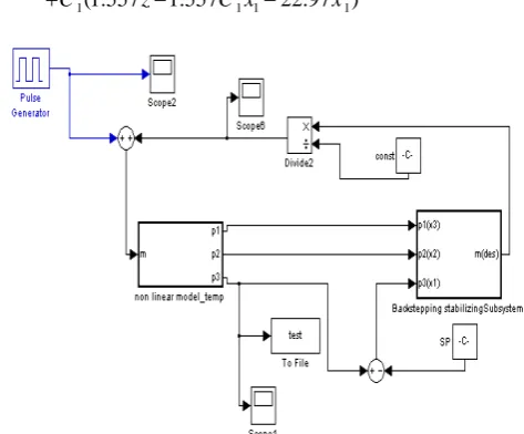
[image:2.595.308.545.206.402.2]
Figure 1. The system with back stepping controller using stabilizing design.
The second Lyapunov function is selected as
2 2
2 1
1 1
( ) . .
2 2
V x
x
z
V x2( ) x x1 1 z z1 1
2 1 1 1 1
3 2 2 1
1 1 1 1
( ) (1.557 1.557 22.97 )
[ (0.455 0.227 ) 0.029 0.014
(1.557 1.557 22.97 )]
V x x z C x x
z m x x x x
C z C x x
Now the desired value of m, m(des) to make V x2( )
negative definite is given by
1 1 2 3 2 1.557 1.557 ( ) ( ) 0.455 0.227
x C z
m des C z
x x
2. Tracking Design 1
2 1
1.557 22.97
ref ref
z x x
z x x x
Control Lyapunov function is selected as
2
1 1
( ) .
2
V z
z
Derivative of V1(x) becomes,
V z1( ) z z
V x1( ) z xref 1.557zx2 22.97zx1
Now the desired value of x2 to make V z1( )
negative definite is given by,
2 1 1 1
22.97 ( )
1.557 1.557 ref
x
x des C x x
,
Where, C1 is a positive constant.
2 2des y x x
Let,
2 1 1
22.97
1.557 1.557
ref x
x y C z x
.
Now, z 1.557y 1.557C z1
2
1
2 1.557 1 1.557
y x C y C z
The second Lyapunov function is selected as 2
2 2
1 1
( ) . .
2 2
V z
z
y
V z2( ) z z y y
2 1 2 3 2
2 2
1
2 1 1
( ) 1.557 1.557 (0.455 0.227 )
0.029 0.014 1.557 1.557
V x zy C z my x x
yx yx C y C yz
[image:3.595.211.523.47.644.2]
Figure 2. The system with back stepping controller using tracking design.
Now the desired value of m, m(des) to make V z2( )
negative definite is given by
IV.
2
2 1 1 1
2
3 2
0.029 0.014 1.557 1.557
( ) ( )
0.455 0.227
x x C y C z
m des C y
x x
IV.SIMULATION AND RESULTS
Extensive simulations have been performed using Matlab- Simulink Software to examine stabilizing and tracking control action of the nonlinear back stepping controller applied for Hypersonic wind tunnel
.
A. Servo operation
In servo operation, the ability of a controller to track changes in set point (requirement) is evaluated. Simulations were done at the two set points of 70 bar and 100 bar, with the values of the positive constants, C1 and C2 of the backstepping controller as 750, 1000, 1500, 2000 and 3000.
1. Controller using Stabilizing design
Figure 3 to figure 6 show the servo operation of the backstepping controller using stabilizing design and the performance comparison results are tabulated in table1.
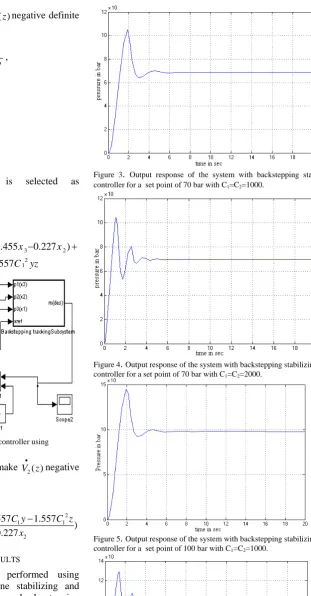
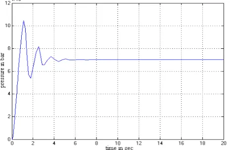
Figure 3. Output response of the system with backstepping stabilizing controller for a set point of 70 bar with C1=C2=1000.
[image:3.595.308.528.54.211.2]Figure 4. Output response of the system with backstepping stabilizing controller for a set point of 70 bar with C1=C2=2000.
Figure 5. Output response of the system with backstepping stabilizing controller for a set point of 100 bar with C1=C2=1000.
[image:3.595.49.309.67.500.2] [image:3.595.305.524.606.760.2]Table 1: Performance comparison of servo operation- Stabilizing design
2. Controller using Tracking design
Figure 7 to figure 10 show the servo operation of the backstepping controller using tracking design and the performance comparison results are tabulated in table2.
Figure 7. Output response of the system with backstepping tracking controller for a set point of 70 bar with C1=C2=1000.
Figure 8. Output response of the system with backstepping tracking controller for a set point of 70 bar with C1=C2=2000
[image:4.595.306.539.241.395.2]Figure 9. Output response of the system with backstepping tracking controller for a set point of 100 bar with C1=C2=1000
Figure 10. Output response of the system with backstepping tracking controller for a set point of 100 bar with C1=C2=2000
Table 2: Performance comparison of servo operation- Tracking design
In the servo operation, comparing to the results obtained in table 1 and table 2, the performance of the controller using tracking design has less offset compared to the controller with stabilizing design. The settling time is also less for the tracking design controller. So we can infer that, when a sudden change in set point is made to the system (servo operation), the tracking design of controller has better performance than the stabilizing design of the controller.
B. Regulator Operation
In regulator operation, the ability of a controller to resist the disturbances affecting the system (load changes) is evaluated.
Set Point
C1,C2 Settling
time in sec
Offset (bars)
%Over shoot
IAE *108
ISE *1014 70
bar
1000 4 1.5 50 1.11 6.7 1500 4.4 0.7 57 1.17 7.03 2000 3.3 0.5 50 1.5 8.41 100
bar
1000 4.2 2 45 1.63 14 1500 4.6 1 36 2.19 17.6 2000 3.5 0.9 29 3.57 26.8
Set Point
C1,C2 Settling
time in sec (2% tolerance)
Offset (bars)
% Over shoot
IAE X108
ISE X1014 70
bar
1000 3.8 0.5 51 1.08 6.72 1500 4.3 003 57 1.13 7.03 2000 3.9 0.01 50 1.47 8.35 100
bar
[image:4.595.47.278.321.473.2] [image:4.595.47.281.511.663.2]An external disturbance in valve position in the form of an impulse with amplitude, period and pulse width of 10, is given to the system at 10 sec, when the system is in the set point. Results are obtained by giving this disturbance when the system is at the set points of 70 bar and 100 bar, and with different values of the positive constant C1 and C2.
1. Controller using Stabilizing design
Figure 11 to figure 14 show the regulator operation of the backstepping controller using stabilizing design and the performance comparison results are tabulated in table3.
Figure11. Regulator response of the system with backstepping controller when a disturbance is applied, at the set point is 70 bar withC1=C2=1000.
Figure12. Regulator response of the system with backstepping controller when a disturbance is applied, at the set point is 70 bar with
C1=C2=2000.
Figure13. Regulator response of the system with backstepping controller when a disturbance is applied, at the set point is 100 bar with C1=C2=1000.
[image:5.595.317.556.246.416.2]Figure14. Regulator response of the system with backstepping controller when a disturbance is applied, at the set point is 100 bar with C1=C2=2000.
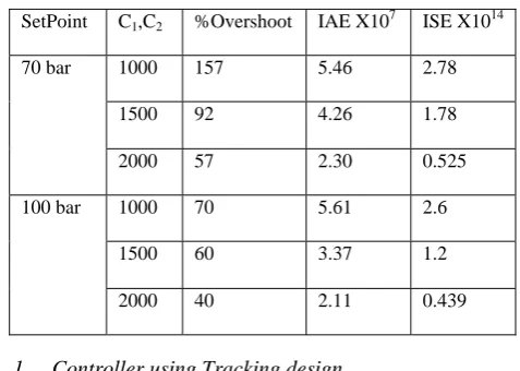
Table 3: Performance comparison of regulator operation- Stabilizing
1. Controller using Tracking design
Figure 15 to figure 18 show the regulator operation of the backstepping controller using tracking design and the performance comparison results are tabulated in table4.
Figure15. Regulator response of the system with backstepping controller when a disturbance is applied, at the set point is 70 bar with C1=C2=1000.
In the regulator operation, comparing to the results obtained in table 3 and table 4, the performance of the controller using tracking design and stabilizing design are almost same. Even then, we can say that for a disturbance given, when the system is at the set point (regulator operation), there is a slight improvement in performance for the stabilizing design in terms of IAE and ISE.
SetPoint C1,C2 %Overshoot IAE X107 ISE X1014
70 bar 1000 157 5.46 2.78 1500 92 4.26 1.78 2000 57 2.30 0.525 100 bar 1000 70 5.61 2.6
Figure16. Regulator response of the system with backstepping controller when a disturbance is applied, at the set point is 70 bar with C1=C2=2000.
Figure17. Regulator response of the system with backstepping controller when a disturbance is applied, at the set point is 100 bar with C1=C2=1000.
[image:6.595.47.273.55.201.2]Figure18. Regulator response of the system with backstepping controller when a disturbance is applied, at the set point is 100 bar with C1=C2=2000.
Table 4: Performance comparison of regulator operation- Tracking
V. CONCLUSION
A stabilizing and tracking design controller using the back stepping technique is designed and implemented for a hypersonic wind tunnel. Compared with the PI and the fuzzy assisted PI controller [7,8], the back stepping controller has improved settling time at different set points and also, when a disturbance is given, the controller takes corrective action to stabilize the system at the desired set point. The back stepping controller utilizes feedback of internal states so that the controller is more predictive and feed forward in nature. This may be the reason for fast settling and better disturbance rejection.
From the studies made by the servo and regulator operation in the tracking and stabilizing design, we can infer that the tracking design is best for the servo operation and the stabilizing design has better performance in the regulator operation. The results show slight offset, which is inherent with a back stepping controller [10]. It can be eliminated by incorporating an integrator in the controller.
REFERENCES
[1] Jie Chang, and Yaolong Tan, “Synthesis and experimental implementation of DSP based Backstepping control of positioning systems”,Journal of Power Electronics, Vol. 7, No. 1, January 2007. [2] Paw Yew Chai,” Attitude control of Mini-UAV using backstepping
Control”thesis submitted, October 4, 2007.
[3] Sang-Seung Lee, Shan-Ying Li, “Nonlinear adaptive back-stepping controller design for power system stabilizer in multi-machine power systems”, 2008 American Control Conference Westin Seattle Hotel, Seattle, Washington, USA, June 11-13, 2008.
[4] M.S. Merzoug , H. Benalla,” Nonlinear Backstepping Control of Permanent Magnet Synchronous Motor (PMSM)” International Journal of Systems Control (Vol.1-2010/Iss.1)pp. 30-34
[5] Eric M. Braun, Frank K. Lu, Philip K. Panicker, Richard R. Mitchell and Donald R, Supersonic Blowdown Wind Tunnel Control Using LabVIEW,46th AIAA Aerospace Sciences Meeting and Exhibit, Reno,
Nevada, January 2008
[6] Varghese Jacob, Binu L.S., Adaptive Fuzzy PI controller for Hypersonic Wind Tunnel Pressure Regulation; National Conference on Technological Trends, Nov 2009.
[7] Rini Jones S.B, P.Poongodi, Binu L.S, ‘Fuzzy assisted PI controller for pressure regulation in a Hypersonic Wind Tunnel', International journal for Hybrid Information Technology ,Vol.4 No.1,January 2011, pp 13-24.
[8] Rini Jones S.B, P.Poongodi, Binu L.S, ‘Design of PI controller with Anti- reset wind up for a Wind Tunnel', International Conference on VLSI, Communication & Instrumentation (ICVCI) 2011, proceedings published by International Journal of Computer Applications® (IJCA).
[9] Rajani S.H, Binu L.S, ‘Backstepping control for regulating pressure inside a hypersonic wind tunnel’ International conference on technological trends, Nov 2010.
[10] Robert Mahony, Tarek Hamel,’ Image based visual servo control of aerial robotic systems using linear image features’,IEEE transactions on robotics, Vol. 21, No. 2, April 2005.
[11] Ola Ha¨rkeg_ard ‘Flight Control Design Using Backstepping’ Department of Electrical Engineering, Link¨opings university, Sweden. ISBN 91-7219-995-4, ISSN 0280-7971.
[12] Noor Asyikin, Azdiana binti, Sharatul Izah ‘ Solving Tracking problem of a non holonomic wheel mobile robot using backstepping technique´Journal of mechanical Engineering and Technology, Vol2, No.1 Jan-June 2010, pp85-92.
[13] David Maurice Cooper ‘ Non linear tracking by trajectory regulation control using backstepping method’, Thesis submitted, June 2005, Ohio university.
Set Point C1,C2 % Overshoot IAE X 10 7
ISE X1014 70 bar 1000 128 4.87 2.64
1500 94 4.46 1.98 2000 57 1.91 0.421 100 bar 1000 75 4.94 2.4