355
METHODS OF MEASURING THE EVAPORATION
OF WATER FROM ANIMALS
BY J. A. RAMSAY.
(From the Zoological Laboratory, Cambridge, and from the Freshwater Laboratory, Wray Castle.)
(Received zoth May, 1935.)
(With Five Text-figures.)
INTRODUCTION.
DURING the past five years this problem of the evaporation of water from animals has attracted considerable attention, particularly from entomologists. Considerable advances have been made, but when the technique of various workers is examined from a physical standpoint it is difficult to see how far laboratory results can be applied to ecological problems in the field. During the last two years this aspect of the subject has been considered, and it is the purpose of this paper to draw attention to the purely physical problems which lie at the base of any attempt to establish a relation between the loss of water from an animal and the evaporating power of the air. No attempt is made to give a comprehensive survey or criticism of the methods of other workers: the examples quoted have been chosen merely to illustrate the argument.
GENERAL PHYSICAL CONSIDERATIONS.
356 J. A. RAMSAY
Under ordinary circumstances, therefore, evaporation is practically a process of gaseous diffusion and may be treated under two heads, evaporation in still air and in moving air.
(1) Evaporation in still air.
Let us consider a vertical tube of uniform bore having a layer of water at the bottom. The theory of diffusion is based on the assumption that the rate of diffusion at any point is proportional to the concentration gradient at that point, and mathe-matical argument leads to the conclusion that if the tube be of infinite length and if the air in it be, initially, unsaturated, then evaporation will take place at a rate which falls off exponentially with time, eventually becoming zero after infinite time when all the air in the tube is saturated. No steady state is ever attained.
Now suppose that at a finite distance above the water surface the tube is closed with a surface capable of maintaining a constant vapour pressure of water, pd, in
contact with it. Let p0 be the vapour pressure of water in the layer of air
imme-diately in contact with the water surface (it is generally assumed that this layer of air is saturated with water vapour at the temperature of the surface). Then if
p0 >pd evaporation will take place and the rate of evaporation will approach
ex-ponentially towards a steady state. This steady state is reached theoretically only after infinite time, but a state which is for practical purposes steady will be reached in a time which depends on the size of the system. When this steady state is reached, the concentration gradient must be uniform throughout the system and the partial pressure of water vapour in the air must decrease linearly from p0 at the water
surface to pd at the drying surface. Thus the concentration gradient, which is
pro-portional to the partial pressure gradient, is n , where D is the distance between
the two surfaces.
Then E KAPo~jf\ (1)
where E= mass of water evaporated in unit time.
A = the cross-sectional area of the tube.
p0 = the partial pressure of water vapour in air saturated at the temperature
of the surface of water.
pd = the partial pressure of water vapour in air in equilibrium with the drying
agent surface.
D = the distance between the surface of water and the drying surface. K is a constant which depends on the temperature and total pressure of the
system. Actually KozTrjP, where T= absolute temperature, P= total
pressure, and r is a constant whose value is approximately 2.
Jeffreys (1918) has considered a special case and has shown that if a wet surface of dimensions 1 cm. square or smaller be placed in an infinitely large atmosphere which is unsaturated with water vapour, a steady state will be reached and the rate of evaporation will be given by an equation of the type
where E, p0 and pd have the same significance as in equation (1).
Coc linear dimensions of the wet surface.
K' is a constant proportional to J^/P, just as the constant K in equation (1).
This equation implies that when the steady state is reached the concentration gradient is not uniform, but rapidly decreases as one passes away from the evapo-rating body so that at a finite distance from it the concentration gradient virtually ceases to exist. Attention is also drawn to the fact that equation (1) contains two constants, A and D, which are functions of the particular form of apparatus used: equation (2) contains no such constants. The conditions of equation (1) are that the concentration gradient extends throughout the whole system: on the other hand, equation (2) will apply if the conditions are such that the concentration gradient does not reach to the boundaries of the system.
(2) Evaporation in moving air.
The effect of a constant current of air is virtually to maintain a surface of constant concentration of water vapour at a constant distance from the evaporating surface. If the wind velocity is about 2 metres/sec. (5 m.p.h.) and the surface is 10 cm. long measured in the direction of the wind, then the concentration of water vapour in the air about 1 mm. above the surface will be the same as that of the oncoming air before it reaches the surface at all. This means that the gradient is very steep, that evaporation is correspondingly more rapid, and that the time taken for the steady state to be reached is correspondingly shorter.
Jeffreys and later Walter (1926) from theoretical considerations arrived at the equation
E^zpVoj^.xiy, (3)
where is = mass of water evaporated in unit time.
p = density of air.
Va = concentration of water vapour in air saturated at the temperature of the
surface. If the oncoming air is not dry but has a concentration of water vapour, Vd, then Vo— Vd is substituted for Vo.
k = effective coefficient of diffusion.
v = wind velocity at a great distance from the surface. x = length of surface measured in the direction of the wind. y = breadth of surface.
358 J. A. RAMSAY
Among other things equation (3) shows that for surfaces of the same shape and the same orientation towards the wind, the rate of evaporation
(1) is zero when the wind velocity is zero, i.e. no steady state is attained, (2) is proportional to the 1-5 power of the linear dimensions of the evaporating surface,
(3) is proportional to the square root of the wind velocity when this is low, and is directly proportional to the wind velocity when this exceeds a certain value. The second point has been verified by Walter and by Thomas and Ferguson (1917). Banerji and Wadia (1932) have shown that, in their experiments on
evapo-c . r , . rate of evaporation . . . .
ration from a tank of water, the ratio , is constant to within V wind velocity
20 per cent.
Jeffreys further considers the rate of evaporation from a hollow cylinder, wet at the bottom and open at the top, and the effect thereon of a wind blowing over the top. He finds the following relation:
E - pV° (A)
where / is the length of the cylinder,
a is the radius of the cylinder,
and the other symbols have the same meaning as in equation (3).
As / decreases, the effect of v on E increases, and when / = o, E = 3-95/3 Fo
i.e. the system is simply a flat surface of water. On the other hand as / increases
the effect of v becomes less.
Equation (3) does not indicate the effect of temperature upon the rate of evapo-ration, and is not, with certainty, applicable to systems other than a flat surface of water. With a view to putting these problems to experimental test it was decided to investigate the rate of evaporation from a simple physical system. For this purpose a free surface of water has certain disadvantages: it is subject to ripples in a strong wind, and the rim of the container introduces a serious disturbance of the air current. Accordingly a porous pot, 7 cm. long and 1 cm. in diameter, was chosen as the experimental object. A wooden cone was fixed to one end in order to make it "stream-lined".
Apparatus.
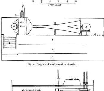
The apparatus consisted of a totally enclosed, return flow wind tunnel, the air current being controlled in temperature, humidity and velocity. Most of the apparatus was built of deal, but the tapering parts of the tunnel proper were of sheet iron and the junction between the entrance to this and the wood was of sheet rubber. Dimensions are shown in Fig. 1, and I wish to express my thanks to Prof. G. I. Taylor and Mr W. S. Farren for their advice on these matters. The air was drawn through the tunnel by fan A driven by a I h.p. motor, and returned through the flues F ^ in the lower half of the apparatus. The experiments were carried out in the narrow experimental section of the tunnel, C.
each side a glass window 6 x 1 in. The front part was roofed and floored with \ in. three-ply wood, the back part was floored with a single piece of J in. ebonite and roofed with three transverse strips of \ in. ebonite. These were each 10 in. long (that is in the direction transverse to the tunnel): the middle strip was fixed in position and the other two were free to slide across. Any instrument mounted on such a strip could be made to traverse the whole breadth of the tunnel.
[image:5.451.79.366.387.508.2]Fig. 1. Diagram of wind tunnel in elevation.
Fig. 2. Diagram of the experimental section, C, of the wind tunnel in elevation.
Wind velocity.
The wind velocity in the experimental section, C, was measured by means of a pitot-and-static tube mounted on one of the ebonite slides. The tube was capable of vertical movement and this, combined with the transverse movement of the slide, enabled every part of the cross-section of C to be explored with the instrument. The velocity distribution was found to be uniform over most of the cross-section, though of course gradients existed in the proximity of the walls or of any object mounted in the tunnel.
360 J. A. RAMSAY
error of ±0-25 metre/sec, at a velocity of 5 metres/sec, and +(vo5 metre/sec, at 20 metres/sec. Owing to the greater error at low velocities experiments were seldom done at velocities less than 4 metres/sec.
Velocities up to 25 metres/sec, (approx. 55 m.p.h.) were obtainable and were con-trolled by resistances in the motor circuit. Variations in the D.C. mains necessitated constant attention to this factor: it would undoubtedly have been possible to arrange an automatic control, but the time required to construct such an apparatus, which must certainly have been elaborate, argued in favour of the more tedious method of direct control by the experimenter.
Humidity.
The middle flue, F2, was fitted at either end with shutters which could be opened and closed from outside. It was originally proposed to control the humidity of the air current by placing trays of CaClj in this flue and regulating the amount of air passing over them. But the wood of which the apparatus was built constituted such a relatively enormous reservoir of water that large quantities of CaCl, deliquesced without producing serious changes in the humidity of the air. This might have been overcome by waxing the inside of the wood, but it seemed more profitable to make use of this hygroscopic quality: for it was clear that the wood could be treated as an equilibrating surface which was quite sufficient to buffer any changes in the humidity of the air current which evapo-ration from the experimental object might tend to produce. But in order to decrease the relative humidity of the air by 10 per cent., it would be necessary to abstract a considerable quantity of water from the wood, and this would involve the use of larger quantities of CaClj than had originally been contemplated.
The method finally adopted was to place six trays of perforated zinc carrying CaCl2
across the returning air at E (Fig. 1) with a zinc trough underneath to collect the saturated CaCL, solution as it dripped off. In this way relative humidities as low as 20-30 per cent., depending on the temperature, were obtainable, and provided the temperature was con-stant, the relative humidity was constant to within 2 per cent, over several days, and was not affected by changes of wind velocity. Higher humidities were obtained by removing the CaCl2, by replacing it with wet cotton-wool and by injecting steam. It was thus
possible to obtain a range of humidity from 20-100 per cent, and to maintain the humidity constant. It would have been a matter of some difficulty to have obtained any particular relative humidity, but fortunately the necessity of doing so did not arise: it was sufficient to obtain constant relative humidity at roughly 10 per cent, intervals.
The humidity was measured by the wet- and dry-bulb thermometers which could be mounted on either of the moving slides. Attempts to arrange a continuous supply of water to the wet bulb gave unreliable results, and the practice finally adopted was to insert the wet bulb through a hole in the fixed roof plate and take the reading when its temperature reached a constant value.
Temperature.
at any one spot. It thus became necessary to introduce fan B solely for the purpose of mixing the air before it entered C. Then it was found that the rotary movement imparted to the air interfered with the uniform velocity distribution in C and necessitated the placing of six stationary blades (not shown in Fig. 1) beyond fan B. The irregularities were further smoothed by the perforated zinc screen G. This arrangement was satis-factory in that the temperature and velocity were uniform over almost the whole cross-section of C.
The first thermostatic system tried was that supplied by Messrs Baily, Grundy and Barrett, consisting of a thermionic relay and a mercury thermometer which, on being heated, closed the circuit operating the relay and switched off the heating current. The volume of mercury was about 3 c.c, and so great was the lag of the instrument that the temperature fluctuations of the air current were of the order of 30 C. An accuracy of ±o-O5°C. was desired, and it was clear that some instrument of low heat capacity and large surface must be used. A light bimetallic spring was ruled out owing to the vibration of the motors: similarly a hot-wire system would have suffered interference from variations in wind velocity. There still remained the thermocouple which had none of these disadvantages.
Short of having an extremely large number of thermocouples it is necessary to amplify the current to make it work a relay, and in this respect thermocouples have a disadvantage in that their low E.M.F. renders valve amplification unsuitable. Amplification was still possible, however, using a mirror galvanometer and allowing the light reflected from it to fall on a photo-electric cell, the current from this latter operating the relay.
A Weston photo-electric cell was used, and the relay which it operated was constructed at the Zoological Laboratory. It consisted of a bifilar suspension galvanometer bearing a platinum wire on the coil former at right angles to the suspension. As the coil swung round the platinum wire made contact with a mercury bead. Sticking of the contact was prevented by subjecting the whole instrument to a slight vibration by bubbling com-pressed air through a tube of mercury attached to the base. Careful adjustment of the compressed air flow and of the mercury bead made it possible to obtain satisfactory contact when the photo-electric cell was fully illuminated, and opening of the circuit when half the light was cut off. The closure of the circuit operated a Baily, Grundy and Barrett thermionic relay, and this in turn switched on or off the heating current in D. It would, of course, have been possible to obtain a single relay for this purpose, but the arrangement used saved expense.
Using a Pointolite lamp and a concentrating lens it was found that the maximum distance from the galvanometer at which the photo-electric cell was sufficiently illuminated to work the relay was about 70 cm. The diameter of the cell was 4 cm. Thus a deflection of 4 cm. at 70 cm. distance must be made equivalent to about o-i° C. It was clear that if one set of thermo-junctions was immersed in ice and the others kept at 15-300 C. the number of thermo -junctions necessary to give this sensitivity would at the same time produce a current too large to be measured by the galvanometer. This difficulty was overcome by balancing the current from the thermopile with an accumulator and potentio-meter, using the galvanometer as null-point instrument. This system had the further advantage that practically no current passed through the thermopile, and in this way the tendency of the hot junctions, being in air, to cool below the air temperature and thus to be affected by wind velocity, was practically eliminated.
Ten constantan-copper thermocouples were connected in series, the hot junctions being stretched across the entrance to C at H in Fig. 1, and the cold junctions being kept in ice in the thermos flask /.
When the air current had reached the desired temperature, the system was arranged so that the beam of light covered one-half of the photo-electric cell. Any increase in temperature caused further illumination of the photo-electric cell, set the relays working and cut off the heating current to D.
362 J. A. R A M S A Y
When properly adjusted this system worked satisfactorily and control accurate to ± 0-025° C- was obtainable with a little care. It was essential, particularly when the wind velocity was low, that the rate of heating should be low: otherwise the hot air came round in a sudden wave, the beam of light was swung past the photo-electric cell suddenly, and the heating circuit, after a brief opening, was closed again. The apparatus worked best at about 3-100 C. above room temperature: if the difference was greater, the rate of cooling was too fast and the temperature fluctuations were larger.
Turbulence.
The air passing through C was in turbulent motion: a smoke trail introduced just beyond G was rapidly dissipated. Relatively stream-line movement could be obtained by removing fan B and inserting a "honey comb" of 1 in. squares 8 in. deep. A smoke trail now remained discrete, and its lateral excursions were of the order of \ in. Un-fortunately this arrangement interfered with the control of temperature, and if gradients in C were to be avoided it could only be used when the apparatus ran at room temperature. While perfectly stream-line air movement is a theoretical possibility it is not a practical one, and while turbulence may be mathematically definable in the equations of motion it cannot readily be measured. It must be clearly understood that the terms "stream-line " and "turbulent" are used in a purely relative sense in connection with this apparatus.
In order that the turbulence should be of the same order whatever the wind velocity, the motors of the two fans, A and B, were connected in parallel and controlled together by the same series of resistances, so that the ratio of their velocities should be roughly constant.
Exploration with the pitot-and-static tube showed that the porous pot was surrounded by a relatively wide space over which the velocity was uniform. This means that the conditions in the neighbourhood of the porous pot were not affected by the walls of the tunnel. In other words, for practical purposes the porous pot was in a limitless atmo-sphere which moved past it with uniform velocity, and so the values obtained for wind velocity in these experiments have a perfectly general significance, and do not need to be qualified by reference to this particular apparatus.
It will be remembered that Vo and fa have been defined as the concentration and the
partial pressure (the one being proportional to the other) of water vapour in equilibrium with the evaporating surface at the temperature of the surface. It is well known that the temperature of an evaporating body falls below that of the surrounding air. The tem-perature of a surface is difficult to measure without introducing disturbing effects, but fortunately in this problem it is not necessary to make the attempt. The temperature depression of a ventilated wet-bulb thermometer depends only on the temperature and humidity of the oncoming air and is independent of the size and shape of the wet bulb, provided that the wind velocity is 5 m.p.h. or over. Thus if such wind velocities are used the temperature of the surface of the porous pot may be assumed to be the same as that of the wet-bulb thermometer.
The amount of water evaporated from the porous pot was measured directly by the usual potometer method of observing the movement of a water meniscus along a capillary tube.
Effect of wind velocity.
the lines pass to the origin in some such way as indicated by the dotted lines in Fig. 3. It was not possible to investigate these lower ranges of wind velocity with this apparatus owing to the greater error of the pitot-and-static tube at low velocities.
Results of a similar nature were obtained by Scott (1932) for a free surface of water in a wind tunnel.
Table I.
u = wind velocity in metres/scc. i?=rate of evaporation in cu.mm./min.
3o"C. V 4 6-9 1 0 15 2 0 2O°C. V 4 6-9 1 0 IS 2 0
28-5 "n R.H.
E
2 9 0 38-25 48-0
6 2 0
77-0
44'5 "0 R.H. E
1625
—
2775 3 6 5 46-0 3o°C. V 4 6-9 1 0 15 2 0 I5°C. V
V "
6 91 0
15
2 0
45-25 % R.H.
E
2 1 5
2925 36-25 47-S 58-5
45-5 °o R.H.
E I4-S 19-25 24-0 3i-5 39-0 25°C. V 4 6 9 1 0 IS 2 0 i5°C V 4 6-9 1 0 IS 2 0
45-75 % R.H.
E 18-5 25-0 32-0 42-25 52-0
82-5 % R-H.
E °-45 o-6o o-75 1 0 1 25 o
XTt. 28-5. R II
11 5 10 15 20
Wind velocity in metres/sec.
Fig. 3. Effect of wind velocity upon the rate of evaporation from the porous pot.
Effect of humidity.
The relation between rate of evaporation, E, and p0 -pd under various conditions
was examined and the results are given in Table II. It is clear that the relation is practically linear, Ej(po-p,i) being very nearly constant. Table II also gives the
364 J. A. RAMSAY
air,p,— pd, and this again is practically linear. The exact theoretical relation between po—pa and ps—pd is of course very complex: it so happens that it is practically
linear when the temperature is constant.
Table II.
Tn = temperature of dry bulb thermometer.
TH = temperature of wet bulb thermometer.
pv = vapour pressure of water in air saturated at T,, . p, = vapour pressure of water in air saturated at T,,. pi = vapour pressure of water in oncoming air.
£ = r a t e of evaporation in cu.mm./min. D = wind velocity =15 metres/sec.
i5°C. 20" C. 25°C. 3O°C. Tn 8-i 8-65 " ' 4 5
16-2 i4-8
I3-45
n - 7
14-6 14-9 1 6 2 16-5 17-0 i9'35 20-55 17-85 179 19-3 2 4 9
Po
8-i
8-4 10-15
138
1 2 7
n - 6 10-3
12-5 12-7 1 3 8 14-0 14-5 16-85 1 8 1 5
1 5 3 15-4 1 6 8 2 3 6
Pd
4-6
5'2
8-3
1 1 9
100 8-25 6 1 7-3 7-65 9-35 9-8 10-5 1405
1 5 9
9-35 9-4 " • 4 5 21-05 Po-Pd 3'5 3 2 1-85 1-9 2-7 3-35 4 2 5-2 5-05 4-45
4 - 2 4 - 0 2 - 8 2 2 5
5 95 6 0 5'35 2-55 p, 17-5 23-75 31-85 P,-Pd 8-2 7-6 4-5 5-6 7'5
9 2 5
11-4 16-45 16-1 14-4 I3-95 13-25 9 7 0
7-8S
2 2 5
22-45 20-4
io-8
E
3i-5 2 9 3 16-73
Mean
1 8 9
25-0
31 5
38-95 Mean
5O-4 4 9 3 43-4
4 2 2
39-2
2 7 9
22-35 Mean 57-9 58-2 52'3 25-7 Mean E Po-Pd 9 0 9-i5 9-Q5 9-O7
9 9 5 9-25 9-40 9-25 9 4 6
9-7 9-8 9-75
io-o 9-8
1 0 0
9 9 5 9 8 6
9'75
9-7O
9 8 0
1 0 0
9-86 E P.-Pd 3-84 3-86 3-72 3-83 3-38 3'34 3-40 3 4 2
3-385
3 0 6 3 0 6 3-oi 3 0 1 2 9 6 2-88 2-84 2-97 2-57 2-59 2-56 2-38 2-525
Effect of temperature.
When we come to consider the effect of variation of temperature upon the system, the fundamental difference between po—pd and the saturation deficiency
of the oncoming air becomes apparent. From Table II the temperature effect can be calculated. Taking po—pd = 3, the rate of evaporation is 27-2 cu.mm./min. at
150 C. and 29-6 cu.mm./min. at 300 C , this represents an increase of 8-85 per cent. Assuming that the rate of diffusion of water vapour through air is proportional to the square of the absolute temperature (it is probably proportional to a slightly lower power), the calculated increase in rate of evaporation at 300 C. as against 150 C. is 11 per cent. Now taking p,—pd = 8-o we find that the rate of evaporation
These experiments show that, within the limits studied, the effects of the three factors, temperature, humidity and wind velocity, upon the evaporation of water from the porous pot are the same as their theoretical effects upon the evaporation from a free surface of water.
Evaporation from a hollow cylinder.
In reaching equation (4) Jeffreys assumes that the air inside the cylinder is at rest. It seems likely, however, that eddies will be set up at the mouth of the cylinder and may extend their influence some distance down it. Since this system is very roughly comparable to the tracheal system of an insect it was decided to put Jeffreys' conclusion to experimental test.
A brass tube of internal diameter o-8 cm. was mounted vertically so as to open in the middle of a small aerofoil which was set in the wind tunnel (see Fig. 4).
[image:11.451.125.333.252.421.2]V/////Z7
Fig. 4. Diagram of tube and aerofoil mounted in wind tunnel.
About 1 c.c. of ether was placed at the bottom of the tube, ether being preferred to water on account of its more rapid rate of evaporation. Two such tubes were made: the distance from the surface of the ether to the mouth of the tube was 15 cm. in one case and 4 cm. in the other. The rate of evaporation from the longer tube was only slightly affected by wind velocity, but the effect of this factor was very pronounced in the case of the shorter tube: a small plug of cotton-wool in the mouth of the smaller tube abolished this pronounced effect. These results are shown in Table III, and graphically in Fig. 5, and it is concluded that the greater effect of wind velocity in the case of the shorter tube is due to the fact that a circulation is set up in the air just inside the mouth of the tube and that this circulation extends its influence down the tube for a distance of at least 4 cm. It is worth noting that as the wind velocity is increased the rate of evaporation from the short tube increases more rapidly than the rate of evaporation from a free surface of water.
366 J. A. RAMSAY
[image:12.451.65.387.168.490.2]of wind velocity on the rate of evaporation from the thoracic spiracles of the cock-roach (Ramsay, 1935). The results obtained from the cockcock-roach are plotted on Fig. 5 for comparison. But while the effect of wind velocity upon the rate of evaporation from the brass tube is probably the result of a circulation of air set up in the tube by the air stream outside it, this explanation can only with hesitation be extended to tubes of smaller dimensions such as the tracheae of an insect.
Table III.
v = wind velocity in metres; sec. is = rate of evaporation in gm./hour.
Length of tube 1 s cm. Temp. i7-o°C.
Length of tube 4 cm.
Without cotton-wool. Temp. i7-o°C.
0 1 2 0 1 4 0 1 6
4
10 20
o-68 3-84 7-92
4 cm.
With cotton-wool. Temp
V
4
1 0 2O
i6-6°C.
E
0 2 0 3 2 0 2 6
o
J:
I
.3I
e
o a
g © /
/k
/k
X
i
.3
I
2
o a
Wind velocity in metres/sec.
Fig. 5. Effect of wind velocity upon ® evaporation of water from tracheal system of cockroach; A evaporation of ether from tube.
BIOPHYSICAL CONSIDERATIONS.
The simplest method and the one which has been most widely used, e.g. Buxton (1930), Mellanby (1932), consists in placing the animal in an ordinary desiccator over solutions of H2SO4 or KOH of such concentrations as are in equilibrium with
known relative humidities. The animal is weighed at intervals and weight loss is shown to be a measure of water loss.
It is assumed that the animal is in an atmosphere whose humidity is entirely determined by the equilibrating solution, and that evaporation proceeds at a steady rate. Before this steady rate is reached, however, a concentration gradient must be established at least in the immediate neighbourhood of the animal. If the desiccator is large and if the animal is small or if water evaporates from it only very slowly, as in the case of the mealworm, conditions may be such as to make equation (2) applicable. This would certainly not be true in the case of an animal like a newt, which is relatively large and loses water rapidly; under such conditions a concentration gradient will be established throughout the system, and it would be necessary to apply equation (1). The application of this equation must be difficult, since the form of the concentration gradient will certainly not be uniform as demanded by the equation. No doubt the rate of evaporation will be propor-tional to p0 —pi, but it will be practically impossible to find values for A and D.
A modification of this method was used by Gunn (1933). He placed a cock-roach in a 200 c.c. honey jar in which he suspended a small tube containing sulphuric acid of known concentration to control the humidity. Now water is lost fairly readily from the cockroach, and since the surface of acid exposed was small, it is more than probable that the concentration gradient extended to the surface of the acid. Under these conditions equation (2) would not be applicable and equation (1) would be at least as difficult to use as in the previous case considered. The simple and ingenious method described by Mellanby (1934) is also open to criticism. The animal is enclosed in a 100 c.c. bottle containing a small paper hygrometer which can be weighed without removing the stopper from the bottle. If the air in the bottle is still and if evaporation proceeds, there must be an unde-termined concentration gradient in the neighbourhood of the animal. The use to which Mellanby put this apparatus, however, was such that an exact physical interpretation of the results was not required.
In all the methods so far outlined the assumption is made that the air is still: but when a live animal moving actively and respiring is enclosed in a small jar there is every reason to believe that such is not the case. Even when the animal is motionless the possibility of air movements is not excluded. In the first place the fact that water vapour is lighter than air will tend to produce a current of moist air passing upwards from the evaporating body: in the second place the fact that the evaporating body is cooler than the surrounding atmosphere will tend to produce a current of cold moist air passing downwards. It is difficult to speculate on the ultimate effect of these two opposing forces.
368 J. A. RAMSAY
long and i cm. in diameter, was mounted in the axis of the tube, and at the other end was fixed a perforated zinc cage containing anhydrous CaCl2. The tube was
placed vertically in a thermostatically controlled water-bath, and the evaporation from the porous pot was measured by the usual method of observing the travelling of a meniscus in a capillary tube. Readings were taken with the pot at the bottom and with the pot at the top, the tube being inverted: then the tube was packed with glass-wool and the readings were repeated. The results are given in Table IV.
Table IV. Evaporation from porous pot in vertical glass tube.
Date
8. vii. 34
g. vii. 34
io. vii. 34
I I . vii. 34
I I . vn. 34 12. vii. 34
Time
11.30 a.m. 2.15 p.m. 5.30 p.m. 10.00 a.m. 1.30 p.m. 5.15 p.m.
10.30 a.m. 2.30 p.m. 4.30 p.m. 11.00 a.m. 1.40 p.m.
5.30 p.m. 10.00 a.m.
Position of porous pot
Without glass-wool At bottom
At top At bottom
,,
With glass-wool At bottom
At top
„
At bottom Without glass-wool
At bottom
»»
Rate of evaporation cu.mm./min.
i-4
1-41 i-36
O-2O
i-5« i-55
0-55
0-5
0-30 0-336 0-363
1-70
1 59
It appears that evaporation is four to five times more rapid when the pot is at the bottom than when it is at the top, and that the presence of glass-wool largely abolishes the difference in rate in the two positions. It is natural to conclude that when the pot is at the bottom and the tube is not occluded with glass-wool, there is an upward current of moist air which sets up a circulation in the system.
It is clear both from equation (3) and from Fig. 3 that the rate of evaporation is considerably affected by wind velocity and that a given increment in velocity produces a much greater effect when the initial velocity is very small than when it has a larger value. Thus on the whole greater errors are introduced if slight currents arise in air assumed to be still than if the velocity fluctuates in air known to be in motion.
tube and covered the open end with muslin: the tube was then placed in the current of air. They found that the duration of life was inversely proportional to the satura-tion deficiency of the air. It seems probable, however, that what they controlled was the rate at which water diffused from the tube, not the rate at which water diffused from a flea. For this reason it is difficult to accept the conclusion which Bacot and Martin have reached. Leeson (1932) repeated this work using unfed fleas each kept in a separate tube in still air, and found that the duration of life was almost entirely dependent on the temperature: only at lower temperatures was it found that the fleas lived longer in moist air.
THE LAW OF SATURATION DEFICIENCY.
In equations (1) and (2), po—pa expresses the difference between the partial
pressure of water vapour in air saturated at the temperature of the surface, />„, and the partial pressure of water vapour in the air at a distance from the surface, pd.
If the wet surface is at the same temperature as the air, po—pi is the saturation
deficiency of the air, and the rate of evaporation will be proportional to this value. But evaporation involves absorption of heat and consequent cooling of the evapo-rating body. In so far, therefore, as the body is cooler than the air, the expression
Po-pa, to which the rate of evaporation is proportional, is not the same thing as
the saturation deficiency of the air.
According to Mellanby (1932) "under otherwise identical conditions, at all temperatures, loss by evaporation is directly proportional to saturation deficiency". This implies that the effect of temperature on the rate of diffusion is negligible. But we have seen that the rate of diffusion is approximately proportional to the square of the absolute temperature and, if we calculate the rate of diffusion at o° C. and at 300 C , we find that its value is over 25 per cent, greater at the higher tem-perature. This effect obviously cannot be neglected even in the roughest experi-ments.
It seems, then, that at least four objections may be raised against experiments carried out in still air and interpreted on the basis of the law of saturation deficiency: (1) The concentration gradient may extend throughout the system and may be difficult to define.
(2) The effect of temperature on the rate of diffusion cannot be ignored. (3) The temperature of the evaporating surface may be different from that of the air.
(4) Air currents may be set up by movements of the animal or by differences in density.
37° J- A. RAMSAY
it must now be recognised that while true under certain conditions it is really an incomplete statement of the facts, and in the form in which it has been applied is even grossly misleading, since it suggests that the effect of temperature upon gaseous diffusion is negligible.
Equation (2) contains no factor which is concerned with the form of apparatus used. If we can show that our experimental conditions are such that this equation can be applied, then we can make an exact physical interpretation of our results. But, if not, then it must be realised that these results have reference to the par-ticular technique employed, and have not necessarily any general significance.
CONCLUSIONS.
So far we have considered evaporation from what is ultimately a free surface of water. Have we any reason to believe that the equations we have mentioned can be applied to the surfaces of animals ? We know that the body fluids of animals are not pure water, but contain salts which means that the vapour pressure in equilibrium with the body fluids must therefore be less than that in equilibrium with water. The lowering of vapour pressure due to this cause, however, is of a very low order. The vapour pressure of frog's blood at about 200 C. is only about 0-075 m m- Hg less than that of pure water. The saturation deficiencies of the atmospheres with which the skin is in contact may be of the order of 15-20 mm. Hg, so that even when half the water content of the animal has been removed the effect of salts in the body fluid may still justifiably be neglected. Adolf (1932) endeavoured to find an atmosphere which was in equilibrium with a living frog. In this he failed: water evaporated from the frog into an atmosphere already saturated. This was due presumably to the fact that the frog's metabolism maintained its body tem-perature above that of the air, so that a small saturation deficiency always existed. The surface of an insect is usually more or less dry: that is to say, water passes through the integument only slowly, and the vapour pressure subtended at the surface depends to some extent on the rapidity with which the water is evaporated as it reaches the surface. Such a system is beyond the scope of the theoretical considerations of the foregoing section, and no information, either theoretical or practical, appears to exist.
We have seen that the forces involved in evaporation are of a much higher order than those involved in the osmotic processes so far investigated in animals. It seems therefore unlikely that the animal can effectively combat these forces by doing work. Yet there is clear evidence of hygroscopic insects, e.g. the mealworm, in which this property was first discovered by Buxton (1930) and later confirmed by Mellanby (1932). The latter found that mealworms came into equilibrium with an atmosphere of 88 per cent, relative humidity.
As far as insects are concerned the problem is beset by still further compli-cations :
com-ponents, evaporation from the surface and evaporation from the tracheal system, may be differently affected by temperature and wind velocity (see Ramsay, 1935)-(2) The more impermeable the cuticle, the more is the total rate of evaporation likely to be influenced by tracheal ventilation and hence by the activity of the animal.
(3) Owing to the general low level of the rate of evaporation, the water pro-duced by metabolism is significant in comparison with the water lost by evapora-tion: hence, if weight loss is to be used as a measure of water loss, it becomes essential to make a preliminary study of the insect's metabolism. Furthermore, the dry weight/wet weight ratio of certain insects appears to be regulated by the production of metabolic water in the exact amount which compensates for the water lost by evaporation (see Buxton, 1932).
In view of these facts it would indeed be surprising and gratifying to find that the rate of evaporation from an insect could be related to some simple expression such as the equations already quoted. Yet Buxton (1932) claims that "it appears that we have arrived at the physical law which governs the loss of water from an insect". The law referred to is the law of saturation deficiency. Certainly the conception of saturation deficiency rather than relative humidity as the controlling factor is an important advance, but it cannot be said that a complete and satis-factory solution has been reached.
SUMMARY.
1. The physical theory of evaporation in still air and in moving air is outlined. 2. An apparatus is described in which controlled conditions of temperature, humidity and wind velocity are obtained.
3. The effects of these three factors upon the rate of evaporation from simple physical systems have been investigated.
4. Sources of error attaching to experiments carried out in still air are enume-rated.
5. The law of saturation deficiency is shown to be theoretically untrue.
372 J. A. RAMSAY
REFERENCES.
ADOLF, E. F. (1932). Biol. Bull. Woods Hole, 62, 112.
BACOT, A. W. and MARTIN, C. J. (1924). J. Hyg., Camb., 23, 98.
BANERJI, S. K. and WADIA, H. M. (1932). Mem. Indian met. Dep. 25, part 9. BUXTON, P. A. (1930). Proc. roy. Soc. B, 106, 560.
(1932). Biol. Rev. 7, 275.
GUNN, D. L. (1933). J. exp. Biol. 10, 274.
HALL, F. G. (1922). Biol. Bull. Woods Hole, 42, 31.
HALL, F. G. and ROOT, R. W. (1930). Biol. Bid!. Woods Hole, 58, 52. JEFFREYS, H. (1918). Phil. Mag. 35, 273.
LANGMUIR, I. and D. B. (1927). J. phys. Chem. 31, 1719. LEESON, H. S. (1932). Parasitology, 24, 196.
MELLANBY, K. (1932). Proc. roy. Soc. B, 111, 376. (1934)- Proc. roy. Soc. B, 116, 139. RAMSAY, J. A. (1935). J. exp. Biol. 12, 373. RIDEAL, E. K. (1925). J. pltys. Chem. 29, 1585. SCOTT, A. W. (1932). J. R. tech. Coll. Glasg. 2, 620.