Abstract— This paper describes specification and execution of behavioral concepts for Open Distributed Processing (ODP) Computational Language. Open Distributed Processing - ODP is introduced as a general framework upon which open distributed system can be modeled through the viewpoint concept and the use of an object oriented language (Unified Modeling Language UML). The behavior of an ODP system is determined by collecting all possible actions in which the system (acting as an object), or any of its constituent objects, might take part, together with a set of constraints on when these actions can occur. In order to specify the executable behavior of a system and to make the processes of the Computational executable and controllable, the Reference Model for ODP RM-ODP can be used as a meta-model for behavioral specifications. In the Computational language, the behavior is a collection of actions with a set of constraints on when they may occur. Firstly, we give the description and specification of the behavior by the activity diagrams. Secondly, we define the mapping from the concepts of behavior Computational language to BPEL concepts and we present the syntax and the structure of a BPEL Behavior process. Then we generate the corresponding BPEL and computational files to implement the specified process.
Keywords:
RM-ODP, Computational Language, Behavior Business Process Model, BPEL
I. INTRODUCTION
The rapid growth of distributed processing has led to a need for coordinating framework for the standardization of Open Distributed Processing (ODP). The Reference Model for Open Distributed Processing (RM-ODP) [1]-[4] provides a framework within which support of distribution, networking and portability can be integrated. The foundations part [2] contains the definition of the concepts and analytical framework for normalized description of (arbitrary) distributed processing systems. These concepts are grouped in several categories. The architecture part [3] contains the specifications of the required characteristics that qualify distributed processing to be open. It defines a framework comprising five viewpoints, viewpoint language, ODP functions and ODP transparencies. The five viewpoints, called enterprise, information, computational, engineering and technology provide a basis for the specification of ODP systems.
Each viewpoint language defines concepts and rules for specifying ODP systems from the corresponding viewpoint.
The ODP functions are required to support ODP systems. The transparency prescriptions show how to use the ODP functions to achieve distribution transparency. The first three viewpoints do not take into account the distribution and heterogeneity inherent problems. This corresponds closely to the concepts of PIM (Platform Independent Model) and PSM (Platform Specific Model) models in the OMG MDA architecture. However, RM-ODP can not be directly applicable [5]. In fact, RM-ODP only provides a framework for the definition of new ODP standards. Which include standards for ODP functions [6-7]; standards for modeling and specifying ODP systems; standards for programming, implementing, and testing ODP systems.
We treated the need of formal notation for behavioral concepts in the Computational language [8]. Indeed, the viewpoint languages are abstract in the sense that they define what concepts should be supported, not how these concepts should be represented. It is important to note that, RM-ODP uses the term language in its broadest sense: “a set of terms and rules for the construction of statements from the terms”. It does not propose any notation to support the viewpoint languages. Using the Unified Modeling Language (UML)/OCL (Object Constraints Language) [9, 10] we defined a formal semantic for a fragment of ODP behavior concepts defined in the RM-ODP foundations part and in the enterprise language [11]. These concepts (time, action, behavior constraints and policies) are suitable for describing and constraining the behavior of ODP enterprise viewpoint specifications.
A part of UML meta-model itself has a precise semantic [12], [13] defined using denotational meta-modeling approach. A denotational approach [14] is realized by a definition of the form of an instance of every language element and a set of rules which determine which instances are denoted or not by a particular language element. For testing ODP systems [2], [3], the current testing techniques [15], [16] are not widely accepted. A new approach for testing, named agile programming [17] or test first approach [19], is being increasingly adopted. The principle is the integration of the system model and the testing model using UML meta-modeling approach [20], [21]. This approach is based on the executable UML [22]. Executable UML is a major innovation in the field of software development. Use it to produce a comprehensive and understandable model of a solution independent of the organization of the software implementation. It is a highly abstract thinking tool that aids in the formalization of knowledge, and is also a way of describing the concepts that make up abstract solutions to software development problems.
Using BPEL for Behavioral Concepts in ODP
Computational Language
In this context, OCL is used to specify the properties to be tested. The UML meta-models provide a precise core of any ODP tester. We use in this paper the BPEL (Business Process Execution Language for Web Services) (BPEL4WS or BPEL for short) to specify process behavior based on interaction and the binding object in the ODP systems. The BPEL is an XML-based standard for defining how you can combine Web services to implement business processes. It builds upon the Web Services Definition Language (WSDL) and XML Schema Definition (XSD). This article specifies the behavior processes by the activity diagrams, and generates the corresponding BPEL and computational files to implement that process. This capability is used to highlight some benefits of the Object Management Groups (OMG) Model Driven Architecture (MDA) initiative: raising the level of abstraction at which development occurs; which, in turn, will deliver greater productivity, better quality, and insulation from underlying changes in technology.
The paper is organized as follows. Section 2 introduces, both BPEL and the core behavior concepts (time, action, state, behavior, interaction and the binding object). Section 3 describes and specifies the behavior by the activity diagrams. In Section 4, we define the mapping from the concepts of behavior computational language to BPEL concepts and we present the syntax and the structure of a BPEL Behavior process. We focus on behavioral interaction. A conclusion ends the paper.
II. PRELIMINARIES
A. According to Wikipedia “Enterprise Architecture is the practice of applying a comprehensive and rigorous method for describing a current and/or future structure and behavior for an organization's processes, information systems, personnel and organizational sub-units, so that they align with the organization's core goals and strategic direction. Although often associated strictly with
information technology, it relates more broadly to the practice of business optimization in that it addresses business architecture, performance management,
organizational structure and process architecture as well.” A widely known example of Enterprise Architecture (EA) is Federal Enterprise Architecture (FEA) [3], which is the US Government’s EA initiative to improve its business operations with a set of its EA Reference Models. Those Reference Models include Performance Reference Model, Business Reference Model, Service Component Reference Model, Data Reference Model, and Technical Reference Model. Each Reference Model provides architecture of the government’s IT systems from the perspective it focuses on. Those FEA reference models provide general structure and fairly detailed categories or ontology of government’s businesses. A number of nations have been working to take advantage of EA, and one example is an EA initiative by Japanese government (JEA for short). JEA can be considered as customized subset of FEA with extensions. Although FEA does not provide guideline for defining FEA models, it provides suggested notations for defining models.
Business Process Execution Language (BPEL) is a XML-based language used to define enterprise business
processes within Web services. Every company has its unique way of defining its business process flow. The key objective of BPEL is to standardize the format of business process flow definition so companies can work together seamlessly using Web services. BPEL extends the Web services interaction model and enables it to support business transactions. BPEL is based on Web services in the sense that each of the business process involved is assumed to be implemented as a Web service. Processes written in BPEL can orchestrate interactions between Web services using XML documents in a standardized manner. These processes can be executed on any platform or product that complies with the BPEL specification.
RM-ODP and EA are different architectures covering similar problem domain. There is an issue of interoperability or reuse of models/specifications between the two. For instance, a Business Reference Model based business models will not be easily incorporated into ODP enterprise specifications, since their concerns and concepts are similar but not exactly the same.
2.1 BPEL
B. BPEL, also known as BPEL4WS, build on IBM's WSFL (Web Services Flow Language) and Microsoft's XLANG (Web Services for Business Process Design). It combines the features of a block structured process language (XLANG) with those of a graph-based process language (WSFL). BPEL is intended to describe a business process in two different ways: executable and abstract processes. An abstract process is a business protocol specifying the message exchange behavior between different parties without revealing the internal behavior of any of them. An executable process specifies the execution order between a number of constituent activities, the partners involved, the message exchanged between these partners and the fault and exception handling mechanisms.
A composite service in BPEL is described in terms of a process. Each element in the process is called an activity. BPEL provides two kinds of activities: primitive activities and structured activities. Primitive activities perform simple operations such as receive (waiting for a message from an external partner), reply (reply a message to a partner), invoke (invoke a partner), assign (copying a value from one place to another), throw (generating a fault), terminate (stopping the entire process instance), wait (wait for a certain time) and empty (do nothing).
(inverse some effects which happened during the execution of activities), and the primary activity of the scope which defines its behavior.
The sequence, flow, switch, pick and whi1e constructs provide a means of expressing structured flow dependencies. In addition to these constructs, BPEL provides another construct known as control links which, together with the associated notions of join condition and transition condition, support the definition of precedence, synchronization and conditional dependencies on top of those captured by the structured activity constructs. A control link between activities A and B indicates that B cannot start before A has either completed or has been skipped. Moreover, B can only be executed if its associated join condition evaluates to true, otherwise B is skipped. An activity X propagates a positive value along an outgoing link L if and only if X was executed (as opposed to being skipped) and the transition condition associated to L evaluates to true. Transition conditions are Boolean expressions over the process variables. The process by which positive and negative values are propagated along control links, causing activities to be executed or skipped, is called dead path elimination [23]. Figure 1 defines the BPEL core concepts [24]
2.2 The Core behavioral Concepts in RM-ODP Foundations Part
We consider the minimum set of modeling concepts necessary for behavior specification. There are a number of approaches to specify the behavior of distributed systems proposed by searchers with different background and
considering different aspects of behavior. We use the formalism of the RM-ODP model, written in UML/OCL, and mainly the concepts taken from the clause [Part 2 – 8.6] of the RM-ODP:
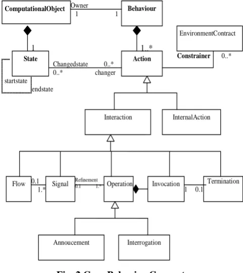
Behavior of an object. Behavior is a collection of actions that the object may take part in, together with the set of constraints on when those actions can occur. The object model does not constrain the form or nature of object behavior. The actions can be interactions of the object with its environment or internal actions of the object.
State. State and behavior are interrelated concepts. The state of an object is the condition of the object at a given instant that determines the potential future sequences of actions that object may be involved in. At the same time, actions bring about state changes and, hence, the current state of an object is partly determined by its past behavior.
Interactions. RM-ODP prescribes three particular types of interactions: signals, operations, and flows. A signal may be regarded as a single, atomic action between computational objects. Signals constitute the most basic unit of interaction in the computational viewpoint. Operations are used to model object interactions as represented by most message passing object models, and come in two flavors: interrogations and announcements. An interrogation is a two-way interaction between two objects: the client object invokes the operation (invocation) on one of the server object interfaces; after processing the request, the server object returns some result to the client object, in the form of a termination. An announcement is a one-way interaction between a client object and a server object. In contrast to an interrogation, after invocation of an announcement operation on one of its interfaces, the server object does not return a termination. Terminations model every possible outcome of an operation. Flows model streams of information, i.e., a flow represents an abstraction of a sequence of interactions from a producer to a consumer, whose exact semantics depends on the specific application domain. In the ODP computational viewpoint, operations and flows can be expressed in terms of signals [1]-[4].
There are many specification styles for expressing when actions may occur (e.g. sequencing, pre-conditions, partial ordering, etc.). The actions and their ordering can be defined in terms of processes. A process identifies an abstraction of the object behavior that includes only those actions that are related to achieving some particular role. Each abstraction is labeled with a process name. The emphasis is on what the behavior achieves. Processes decompose the behavior of the object into steps. Its specification shall include specification of how it is initiated and how it terminates.
We represent a concurrent system as a triple consisting of a set of behavior, a set of process and a set of action. Each behavior is modeled as a finite or infinite sequence of interchangeable behavior and actions. To describe this sequence, there are mainly two approaches [25].
1. “Modeling systems by describing their set of actions and their behaviors”.
2. “Modeling systems by describing their action spaces and their possible sequences of action changes”.
action sequences can be understood as abstract representations of process. We consider both of these approaches as abstraction of the most general approach based on RM-ODP. We provide the formal definition of this approach that expresses the business process models.
ComputationalObject Behaviour
Action State
Interaction InternalAction
Flow Signal Operation Invocation Termination
Annoucement Interrogation Owner
1 1
1..*
1
Changedstate 0..* 0..* changer startstate
endstate
1 0.1
Refinement 0.1 1.*
0.1 1.*
EnvironmentContract
[image:4.595.311.556.67.247.2]Constrainer 0..*
Fig. 2 Core Behavior Concepts
III. 3. UML PROFILE FOR AUTOMATED BEHAVIOR PROCESSES
The ability to extend or customize UML is essential to MDA; UML can be customized to support the modeling of systems behavior. The scope of this article is mainly centered on stereotypes. Stereotypes are a way of categorizing elements of a model. We can combine a set of these stereotypes in a Profile. A UML Profile is used to define a specific set of extensions to the base UML in order to represent a particular domain of interest. For instance there are Profiles defined for CORBA and Data Modeling. A profile defines what elements of UML are to be used, how they may be extended, and any well-formedness rules to constrain the assembly of the elements.
[image:4.595.52.293.131.401.2]This section introduces a UML Profile which supports modeling with a set of semantic constructs that correspond to those in the Business Process Execution Language for behavior in enterprise language (see table 1).
Table 1 – Sample table
We represent a subset of the UML profile through ODP Trader from the Computational Viewpoint [7] that defines a simple behavior process. It may be summarized as follows:
"ODP aims to provide distribution-transparent utilisation of services over heterogeneous environments. In order to use services, users need to be aware of potential service providers and to be capable of accessing them. Since sites and applications in distributed systems are likely to change frequently, it is advantageous to allow late binding between service users and providers. If this is to be supported, a component must be able to find appropriate service providers dynamically. The ODP trading function provides this dynamic selection of service providers at run time."
BPEL processes are stateful and have instances, so in BPEL this scenario is implemented as a behavior process which would have an instance for each actual behavior application being processed. Each instance has its own state which is captured in BPEL variables. In the UML profile, a process is represented as a class with the stereotype <<Process>>. The attributes of the class correspond to the state of the process (variables in BPEL 1.1). The UML class representing the behavioral process is shown in Figure 3.
<<Process>>
BehaviorProcess :: Behavior
+ request : ActionInformation
+rolesinfo :BehavioRrole
+constraint :RulesBehavior
+error :RequestError
Fig. 3 A UML class used to model a Behavior BPEL Process
Behavior Concepts Profile Construct Process_CV << process>> class
Action Activity graph on a
<<process>> class ObjectRole <<partner>> class
Constraint <<process>> class
attributes
Message Hierarchical structure and control
flow <<receive>>,
<<invocation>>, <<termination>>,
<<announcement>> actions
<<receive>>, <<reply>>,
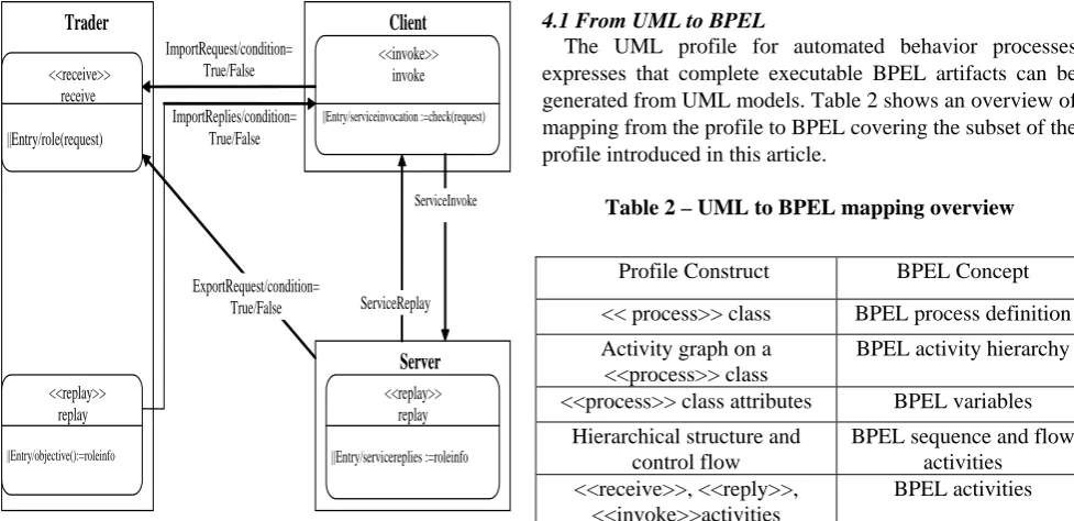
[image:4.595.327.553.576.739.2]The behavior of the class is described using an activity graph. The activity graph for the behavior process is shown in figure 4. The activities, such as invoke, are shown as the rectangles with rounded corners. The actions to be performed are shown as Entry conditions to the activity. For example, action constraint (a variable) is set to the result of the check service. The partners with which the process communicates are represented by the UML partitions (also known as swimlanes): Trader, Client and Server. The activities that involve a message send or receive operation to an partner appear in the corresponding partition. The arrows indicate the order in which the process performs the activities. Note that the assignment activity is not in a swimlane; it depicts an action that takes place within the process itself.
<<receive>> receive
||Entry/role(request)
<<invoke>> invoke
||Entry/serviceinvocation :=check(request)
<<replay>> replay
||Entry/servicereplies :=roleinfo
Trader
<<replay>> replay
||Entry/objective():=roleinfo
Client
Server
ImportRequest/condition= True/False
ImportReplies/condition= True/False
ExportRequest/condition= True/False
ServiceInvoke
ServiceReplay
Fig. 4 – An Activity Diagram for the Behavior Process
The reply activity returns a response back to the client, completing the execution of the process. Each activity has a descriptive name and an entry action detailing the work performed by the activity.
IV. MAPPING TO BPEL
As service-oriented technology gains in popularity, it will be increasingly necessary to be able to design large-scale solutions that incorporate web services. The Unified Modeling Language. (UML.) is widely used in the development of object-oriented software and has also been used, with customizations, for component-based software, business process modeling and systems design. UML provides a visual modeling notation which is valuable for solution design and comprehension. UML can be customized to support the modeling of systems that will be completely or partially deployed to a web services infrastructure. This enables the considerable body of UML experience to be applied to the maturing web services technologies. This paper introduces a UML profile (a
customization of UML) which supports modeling with a set of semantic constructs that correspond to those in the Business Process Execution Language for Web Services1 (BPEL4WS).
Using UML primarily as a documentation tool has a real but limited benefit, and it is recognized that UML models developed for this purpose may not be maintained when a project is under severe time pressure. The value of UML modeling of systems has the potential to increase significantly through the emergence of initiatives such as model-driven development and architected RAD [3] which enable executable systems to be generated automatically from detailed models. This approach is employed here to provide a mapping from models conforming to the UML profile for automated business processes to executable BPEL processes.
4.1 From UML to BPEL
[image:5.595.58.547.254.491.2]The UML profile for automated behavior processes expresses that complete executable BPEL artifacts can be generated from UML models. Table 2 shows an overview of mapping from the profile to BPEL covering the subset of the profile introduced in this article.
Table 2 – UML to BPEL mapping overview
4.2 Execution of the Behavior processes
BPEL is an XML representation of an executable process which can be deployed on any process motor. The atomic element of a process BPEL is an “activity”, which can be the send of a message, the reception of a message, the call of an operation (sending of a message, makes an attempt of an answer), or a transformation of data.
Profile Construct BPEL Concept << process>> class BPEL process definition Activity graph on a
<<process>> class
BPEL activity hierarchy <<process>> class attributes BPEL variables
Hierarchical structure and control flow
BPEL sequence and flow activities <<receive>>, <<reply>>,
<<invoke>>activities
< cv_behavior >
< ObjectRole /> Æ definition of the object role <containers/> Æ definition of the containers of the
data
<transitioncondition>
<constraints /> Æ A set of rules related to a behaviour. </transitioncondition>
<sequence/>
<receive /> Æ reception of a request of process <assign /> Æ transformation of the data
<invocation /> Æ call of an process <termination /> Æ termination of process <announcement /> Æ interaction initiated by a client
object
<reply /> Æ sending of an answer to the process </sequence>
</cv_behavior > <process >
< roles /> Æ definition of the roles <containers/> Æ definition of the containers of the
data <sequence />
<receive /> Æ reception of a request <assign /> Æ transformation of the data
<invoke /> Æ call of an action <reply /> Æ sending of an answer
</sequence> </process>
<messages> name = "namemessage" <process name ="process"/> < causality name = "causality"/>
<choice >
<message type ="invocations"/> < message type ="terminations"/> < message type ="annoucements"/>
< message type ="signal"/> </choice > </messages>
A cut down version of the BPEL document that would be generated from the behavior process example is shown in Listing 1 (much of the detail is omitted here due to space constraints).
Listing 1 Excerpt of the BPEL listing
<process name="behaviorProcess" ...> <variables>
<variable name="request"
messageType="roledef:actionInformationMessage"/> <variable name="action_constraint" messageType="asns: action_constraintMessage"/>
... </variables>
... <flow>
<receive name="receive" partner="trader" portType="apns:behaviorprocessPT"
operation="role" variable="request" createInstance="yes"> <source linkName="receive-to-client"
transitionCondition=
"bpws:getVariableData('request', 'condition') = true"/> <source linkName="receive-to-server"
transitionCondition=
"bpws:getVariableData('request', 'condition)=false"/> </receive>
<invoke name="invokeservice" partner="client" portType="asns:actionconstraint"
operation="check" inputVariable="request" outputVariable="action_constraint"> <target linkName="receive-to-server"/> <source linkName="server-to-setMessage"
transitionCondition=
"bpws:getVariableData('action_constraint ', 'check')='true'"/>
<source linkName="reply-to-invoke" transitionCondition=
"bpws:getVariableData('action_constraint ', 'check')!='true'"/>
</invoke> <assign name="assign">
<target linkName="invoke-to-setMessage"/> <source linkName="setMessage-to-reply"/>
<copy>
<from expression="'yes'"/> <to variable="roleInfo" part="accept"/>
</copy> </assign>
...
<reply name="reply" partner="actor1" portType="apns:behaviorprocessPT" operation="approve" variable="roleInfo"> <target linkName="setMessage-to-reply"/>
<target linkName="role-to-reply"/> </reply>
4.2 The UML to BPEL Mapping Transformation The approach comes with a set of sample files for different scenarios [26]. The sample files are of two main types: UML model files which can be opened and modified with tools, and XML files containing the XMI version of the UML models and which are exported by theme. In figure 5, we can see that this corresponds to the UML models, or the XMI output of these tools. Figure 5 uses a UML Activity Diagram to show the overall process of transforming the files; isn't UML useful? The boxes represent artifacts (usually files) while the ellipses represent an action or activity. The main stages are:
• Building and exporting the UML model to XMI (tools) • Generating the BPEL, Actions, and behavior files • Deploying these on the BPEL motor.
UML model
Requirements Analysis
Functional specification
Design
Implementation XML files
Containing the XMI version of the UML models
Constraints
XSD Schema Interface Definition BPEL Process
BPEL runtime Application Developer
Fig. 5 a process of Developing
V. CONCLUSION AND FUTURE WORKS This article has introduced a UML profile for automated behavior processes with a UML to BPEL translator. The profile allows developers to use normal UML skills and tools to develop behavior processes using BPEL. This approach enables service-oriented BPEL components to be incorporated into an overall system design utilizing existing software engineering practices. Additionally, the mapping from UML to BPEL a model-driven development approach in which BPEL executable processes can be automatically generated from UML models. Although we have only shown our method for the Trader behavior from the Enterprise Viewpoint, the method is generic enough to be applied in other viewpoints, such as trader from the Information Viewpoint. Future work includes the implementation of a reverse mapping to support the import of existing BPEL4WS artifacts and the synchronization of UML models and BPEL4WS artifacts with changes in either being reflected in the other.
REFERENCES
[1] ISO/IEC, ‘’Basic RM-ODP-Part1: Overview and Guide to Use, ‘’ISO/IEC CD 10746-1, 1994
[2] ISO/IEC, ‘’RM-ODP-Part2: Descriptive Model, ‘’ ISO/IEC DIS 10746-2, 1994.
[3] ISO/IEC, ‘’RM-ODP-Part3: Prescriptive Model, ‘’ ISO/IEC DIS 10746-3, 1994.
[4] ISO/IEC, ‘’RM-ODP-Part4: Architectural Semantics, ‘’ ISO/IEC DIS 10746-4, July 1994.
[5] M. Bouhdadi, et al. ‘’ An UML-based Meta-language for the QoS-aware Enterprise Specification of Open Distributed Systems, ‘’ Collaborative Business Ecosystems & Virtual Enterprises, IFIP Series, Vol. 85, Springer Boston, pp.255-264, 2002.
[6] ISO/IEC, ‘’ODP Type Repository Function, ‘’ ISO/IEC JTC1/SC7 N2057, 1999.
[7] ISO/IEC, The ODP Trading Function, ISO/IEC JTC1/SC21 1995. [8] ISO/IEC, ‘’ Use of UML for ODP system specifications’’ ISO/IEC
19793, May 2006.
[9] J. Rumbaugh, G. Booch, J. E. Jacobson, the Unified Modeling Language, Addison Wesley, 1999.
[10] J. Warner and A. Kleppe, The Object Constraint Language: Precise Modeling with UML, Addison Wesley, 1998.
[11] M. Bouhdadi, Y. Balouki, ‘’Meta-modelling Semantics of Behavioral Concepts for Open Virtual Enterprises,’’ ECC 2007, Athens 25-27 Sep, Springer Verlag (to appear)
[12] S. Kent, S. Gaito, N. Ross, ‘’A meta-model semantics for structural constraints in UML, ‘, In H. Kilov, B. Rumpe, and I. Simmonds, editors, Behavioral specifications for businesses and systems, Kluwer Academic Publishers, Norwell, MA, September 1999. Chapter 9. [13] E. Evans, R. France, K. lano, B. Rumpe, ‘’Meta-Modeling Semantics
of UML, ‘’ In H. Kilov, B. Rumpe, and I. Simmonds, editors, Behavioral specifications for businesses and systems, Kluwer Academic Publishers, Norwell, MA, September 1999. chapter 4 [14] D.A. Schmidt, ‘’Denotational semantics: A Methodology for
Language Development, ‘’ Allyn and Bacon, Massachusetts, 1986. [15] G. Myers, ‘’The art of Software Testing, ‘’, John Wiley &Sons, 1979 [16] R. Binder, ‘’ Testing Object Oriented Systems. Models. Patterns, and
Tools, ‘’ Addison-Wesley, 1999
[17] A. Cockburn, ‘’Agile Software Development. ‘’Addison-Wesley, 2002.
[18] B. Rumpe, ‘’ Agile Modeling with UML, ‘’ LNCS vol. 2941, Springer, 2004, pp. 297-309.
[19] K. Beck. Column on Test-First Approach. IEEE Software, vol. 18, no. 5, pp.87-89, 2001
[20] L. Briand , ‘’A UML-based Approach to System testing, ‘’ LNCS vol. 2185. Springer, 2001, pp. 194-208,
[21] B. Rumpe, ‘’ Model-Based Testing of Object-Oriented Systems; ‘’ LNCS vol.. 2852, Springer; 2003; pp. 380-402.
[22] B. Rumpe, Executable Modeling UML. A Vision or a Nightmare?, In: Issues and Trends of Information technology management in Contemporary Associations, Seattle, Idea Group, London, pp. 697-701.
[23] .Duhang Zhong et al.”Reliability Prediction for BPEL-Based Composite Web Service” ,Proceedings of the first international conference On Research challenges in Information science, pages 265,270. Ouarzazate,Morocco,2007
[24] . Dimitris Karagiannis et al. Business-oriented IT management developing e-business applications with E-BPMS,’’ ICEC 2007, 97-100
[25] . M. Broy, ‘’Formal treatment of concurrency and time,’’ Software Engineers’s Reference Book, Oxford Butterworth-Henenmann (1991). [26] . keith Mantell,” From UML to BPEL Model Driven Architecture in a