Abstract— Usage of 3D images for face recognition has become more popular in the past few years since they are not affected by pose changes. Hence, there exists a need to store or transmit 3D images efficiently. This is important when increasing amount of 3D images is needed to be stored in a limited space or sent over a fixed bandwidth channel. A possible solution is to compress the 3D image. Unfortunately, this may cause the recognition rate to drop. In this paper, a 3D face range recognition system with compression is proposed and the effect of using compressed 3D range images on the recognition rate is investigated. The Set Partitioning in Hierarchical Trees (SPIHT) coding technique is proposed to be used for the compression. This technique is an improvement of the Embedded Zerotree Wavelet (EZW) coding technique. From the simulation results, when comparing uncompressed probe images and probe images compressed using SPIHT coding, the compressed image recognition rate ranges from being lower to being slightly higher than uncompressed probe image recognition rate, depending on bit rate. This proves that a 3D face range recognition system using compressed images is a feasible alternative to a system without using compressed images and should be investigated since the benefits like smaller file storage size, faster image transmission time and better recognition rates are important.
Index Terms—3D face recognition, 3D range image compression, SPIHT.
I. INTRODUCTION
Researchers have been trying to automate face recognition for a long time. With accurate face recognition systems, industries like the security sector will benefit from them [1]. From locating dangerous people to verifying the identity of a person going in and out of a building, a face recognition system can be a powerful tool. However, this does not mean face recognition is only to look for criminals. Face recognition can also be used for entertainment, like producing more innovative games as well as help long lost families reunite by helping them search through a database of millions of faces.
Face recognition using two dimensional (2D) images has been thoroughly explored over the years. However, they still suffer from pose changes problem [2]. Therefore, three dimensional (3D) images started to be explored for usage in face recognition. This is because 3D face recognition uses the face surface structure and shape, and can be rotated in any
Manuscript received October 23, 2008.
The authors are with The University of Nottingham, Malaysia Campus, Jalan Broga, 43500 Semenyih, Selangor Darul Ehsan, Malaysia (phone: +603-8924 8358; fax: +603-8924 8017; e-mail: [email protected], [email protected], [email protected], [email protected], [email protected]).
direction to match a face in the database, therefore eliminating the pose changes problem.
An example of a type of 3D image is the range image. This type of image contains the x, y and z coordinate of each face pixel as well as the flag value. Typically, the z-coordinate value is the range value, which is the distance of the face from the camera while the x and y coordinate values are the pixel coordinates. Therefore, when the z-coordinate values are arranged properly in a matrix, then the x and y coordinate values can be ignored. The flag values show whether the pixel has a valid range value or not. However, 3D range images can be large in file size and therefore can pose storage and transmission problems when there is limited space or bandwidth. For example, a 640x480 range image is about 13 Mb in size.
A solution to reduce a large image file size is compression. The main purpose of image compression is to reduce the size of the file while ensuring that the quality of the image do not degrade too much. A compression system typically consists of 3 components, which are source encoder, quantizer and entropy encoder [3]. The source encoder transform the image into coefficients, the quantizer reduces the number of bits of the coefficients and the entropy encoder compresses the quantized coefficients further for better compression [3].
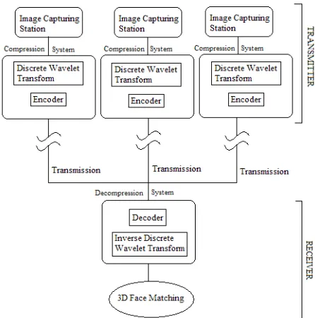
In this paper, a 3D face recognition system with compression is proposed. This system uses 3D face range images and consists of 2 parts, which are transmitters and a receiver. A transmitter consists of an image capturing station and at each station, the 3D range images are compressed before being transmitted. The receiver consists of a decompression system and a 3D face matching system. The proposed system consists of several transmitters and 1 receiver, as shown in Fig 1. The reason is to have several small units of 3D camera that captures 3D range images of unknown people around a building and these images are then sent to the receiver section to perform face recognition to identify the unknown person. The advantage of the proposed setup is to enable the system to have many different locations to capture images without the need to setup a face recognition system at each location. Instead, all the information just needs to be sent to 1 central system to perform the face recognition. Hence, compression is a crucial step to reduce transmission time and save bandwidth.
Section II discusses about the face recognition method used while Section III discusses about the 3D face range image compression. The simulation and results are presented in Section IV and finally the conclusion is in Section V.
II. 3DFACE RECOGNITION
A 3D face recognition method was proposed in [4]. This method comprises of 3 parts, which are face feature detection, face alignment and face matching which consist of surface matching, principal component analysis (PCA) [5] and linear
3D Face Recognition System with Compression
discriminant analysis (LDA) [6]. Fig 2 shows the layout of the 3D face recognition method.
Fig 1: 3D Face Recognition System with Compression In the recognition method proposed in [4], the first step is to locate the face feature points. These feature points were automatically located. The faces are then rotated and translated using those feature points so that the unknown probe faces and those in the database are frontal facing. Each probe and database face was aligned to a fixed position so that they can be matched to each other more efficiently.
Next, the surface matching method is used. The face row with the nose tip is located and then the horizontal face slice is segmented out slice by slice between the nose row and 100 rows above it. This should be the area between the forehead and nose which is less susceptible to facial expression. The distance between the database candidates and unknown probe slice is calculated by the vertical distance. Since each contour slice does not have a line equation, a replacement is to connect each neighbouring point with a straight line. Therefore, the vertical distance line will intersect with two lines from the database and unknown slice and the distance between the two intersection points will be the distance wanted.
Since the faces are not aligned using Iterative Closest Point (ICP) [7], only surface matching will not provide an accurate face recognition result. Therefore, Principal Component Analysis (PCA) [5] followed by Linear Discriminant Analysis (LDA) [6] is further performed on the 20 closest matches from the surface matching result. For the PCA followed by LDA method, instead of using 2D gray images, the proposed method uses 3D range information instead to create the LDA eigenspace. For each face in the database, each horizontal face slice between the nose and forehead is taken and the range value for a fixed interval from the left to right is recorded. All of these values are then systematically aligned into one column per face of a matrix. Therefore, if the database has 100 faces, then the matrix will have 100 columns. Only slices between the nose and forehead is used to avoid the
[image:2.612.330.523.110.390.2]and then LDA [6] are performed to obtain the LDA eigenspace. After that, each unknown probe face will be projected on the LDA eigenspace and the nearest faces will be considered the most likely candidate for the probe.
Fig 2: 3D face recognition method
This 3D face recognition method is performed on both compressed and uncompressed 3D range images to determine how much degradation the recognition rate will have due to using compressed images.
III. 3DRANGE IMAGE COMPRESSION
From Section II, it is observed that 3D range face images were successfully used in a 3D face recognition system. However, a drawback of 3D range images is their file size. At about 13 Mb for a single 640x480 image, storing and sending the image becomes a problem when there is limited space or bandwidth. Therefore, it is proposed that the image be compressed.
In the past, most encoders are Discrete Cosine Transform (DCT) [3] based. First, an image is divided into 8 pixels by 8 pixels blocks of image samples. Then, the 8x8 blocks are each converted into a frequency domain from spatial domain using DCT. This produces 64 DCT coefficients which are uniformly quantized using a 64-element Quantization Table (QT). After that, the quantized coefficients are ordered into a zig-zag sequence, which helps in the entropy encoding since low-frequency non-zero coefficients are placed before high-frequency coefficients [3]. Finally, entropy coding is used to produce additional compression losslessly.
transformation is that it decomposes a signal into various subbands, therefore eliminating the need to block the input image [3]. This ensures that the blocking artifacts problem does not occur at low bit rates. A popular discrete wavelet based image coding technique is Set Partitioning in Hierarchical Trees (SPIHT) and it is briefly discussed below.
A. Set Partitioning in Hierarchical Trees (SPIHT) The SPIHT algorithm was proposed by Said and Pearlman in 1996 [8]. This algorithm is an extension of the Embedded Zerotree Wavelet (EZW) coding algorithm. In the past, it has been assumed that the more efficient a compression code, the complexity will be higher. However, the EZW algorithm managed to perform efficiently but with low complexity. This is due to the embedded bit stream created [8]. Using this bit stream, the reception of code bits can be stopped at any point in time and the image can still be reconstructed. Said and Pearlman extended on the work done by modifying the EZW and adding set partitioning in hierarchical trees. The SPIHT algorithm transmits the larger coefficients first, starting with the most significant bits [8]. Said and Pearlman claims that their SPIHT algorithm surpass the results obtained using EZW [8].
IV. SIMULATION AND RESULTS
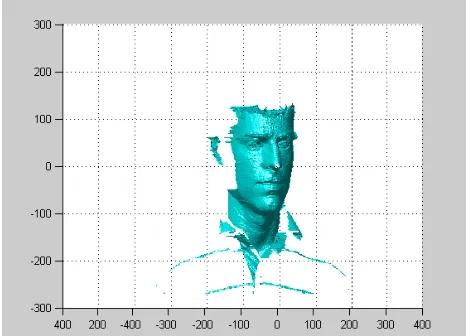
[image:3.612.69.302.427.595.2]The range images are compressed using SPIHT [8] coding and recognition is performed using the method proposed in [4]. The compression is performed from 0.05 bits per pixel (bpp) to 0.50 bpp, at 0.05 bpp interval. Fig 3 shows the original image while Fig 4 shows the decompressed images of the original image at different bit rates using SPIHT coding.
Fig 3: Original Image
0.05 bpp 0.10 bpp
0.15 bpp 0.20 bpp
0.25 bpp 0.30 bpp
0.45 bpp 0.50 bpp
Fig 4: 3D face range image compression at various bit rates The images in Fig 4 are the images obtained after decompression that are used for recognition. However, before the images in Figure 4 can be obtained, another vital step needs to be performed. This is because right after decompression, an outline boundary can be observed surrounding the image. Therefore, this outline needs to be removed before the next stage of face recognition can be performed.
To remove the unwanted boundary, the first step is to binarize the reconstructed range image. Then, the image is eroded a few times to obtain a face mask that is slightly smaller that the original face. Finally, the reconstructed range image is compared with the eroded binarized image and only range pixels within the binarized image are retained. Therefore, the unwanted boundary outline was successfully removed. The shrinking of the binarized image to obtain the face range image should not affect the recognition process since most of the information used for recognition is at the middle of the face. Fig 5 shows a face range image before and after removal of the boundary outline.
Once the boundary outline has been removed, the 3D face range image is matched with a 3D face range database using the method discussed in Section II to determine the identity of the face. The 3D face recognition method consists of performing surface matching followed by PCA and LDA.
Fig 5: Face range image before and after boundary outline removal.
For this simulation, the UND database [9]-[10] was used. Since training for PCA [5] and LDA [6] requires multiple images per subject, a subset of this database was used. It was decided that the training database consist of 3 images per subject. This means subjects with at least 3 images can be selected for training and subjects with at least 4 images can be selected as the unknown probe image. For this paper, 80 subjects were chosen for training while 61 subjects were chosen as the unknown probe. This means there is a total of 240 training images. All of them were rotated to the front with their nose at position (0,0,0). This is to make it easier for the probe face to align itself to the faces in the database.
Each of the unknown probe faces were compressed and then decompressed before performing face recognition using the method of surface matching followed by PCA and LDA. Fig 6 shows the PSNR obtained for several images compressed with SPIHT coding, Table 1 shows the recognition rate obtained for different bit rates after compression using SPIHT coding while Table 2 shows the recognition rate obtained if the images have not been compressed before.
PSNR Vs. Bit Rates
10 15 20 25 30 35 40
0 0.1 0.2 0.3 0.4 0.5 0.6
Bits Per Pixel (bpp)
P
S
N
R
(
d
B
) Image 1
Image 2
Image 3
Image 4
[image:4.612.91.279.47.205.2]Image 5
Fig 6: Graph of PSNR versus Bit rates Table 1: Recognition rates for compressed images for
different bit rates. Recognition Rates (%)
Rank 0.05 bpp 0.10 bpp 0.15 bpp 0.20 bpp 0.25 bpp 1 59.02 65.57 68.85 70.49 72.13
2 65.57 77.05 73.77 73.77 77.05
3 73.77 80.33 75.41 75.41 78.69 4 75.41 80.33 80.33 75.41 80.33
5 77.05 81.97 81.97 81.97 85.25
Recognition Rates (%)
Rank 0.30 bpp 0.35 bpp 0.40 bpp 0.45 bpp 0.50 bpp
1 75.41 77.05 77.05 75.41 73.77
2 78.69 78.69 78.69 78.69 77.05 3 81.97 81.97 81.97 83.61 81.97
[image:4.612.314.541.293.424.2]4 83.61 81.97 83.61 83.61 83.61 5 86.89 85.25 86.89 86.89 86.89
Table 2: Recognition rates for uncompressed images. Rank Recognition Rates (%)
1 68.85
2 73.77
[image:4.612.70.296.526.686.2]In Fig 6, it is observed that the PSNR increases as the bit rate increases. This means that the quality of the reconstructed image is better with higher bit rate. The 3D range images used have PSNR values of between 10 dB to 50 dB.
By comparing Table 1 and Table 2, it can be observed that the recognition rates for the compressed images increases with higher bit rates till 0.40 bpp before dropping a little. From 0.20 bpp onwards, compressed images have 3 to 5 more Rank 1 images compared to uncompressed images, hence a higher recognition rate. A possible reason is a feature of the probe image that causes it to be an unsuitable match to the correct person in the database became less prominent due to the compression. Therefore, with fewer differences, a better match was achieved. The results show that it is possible to compress the 3D face range image and still be able to use it to perform 3D face recognition. Therefore, it proves that the proposed 3D face recognition system with compression is a feasible system.
V. CONCLUSION
In this paper, a 3D face recognition system with compression is proposed. This system consists of a transmitter side which contains image capturing and compression systems, and a receiver side which contains a decompression system and a 3D face matching system. First, the captured unknown probe image is compressed and then uncompressed at a determined bit rate using the SPIHT coder. Then, the uncompressed image is processed to remove the boundary outline that formed after compression. Finally, face recognition is performed using the proposed method of surface matching followed by PCA and LDA. From the results obtained, the recognition rate of the proposed 3D face recognition system with compression varies, from lower to higher than a normal 3D face recognition system without
compression, depending on bit rate. Therefore, this shows that adding compression to a 3D face recognition system is a feasible step and warrants further research since recognition rates obtained were good and the benefits obtained from using compressed images, like reduced storage space and faster transmission time, are important when there is limited storage space or bandwidth
REFERENCES
[1] Identix. FaceIT surveillance SDK http://www.identix.com/, 2005. [2] W. Zhao, R. Chellappa, A. Rosenfeld, and P. J. Phillips, “Face
Recognition: A Literature Survey,” UMD CfAR Technical Report CAR-TR-948, 2000.
[3] Subhasis Saha, Image Compression - from DCT to Wavelets : A Review,2000,
http://www.acm.org/crossroads/xrds6-3/sahaimgcoding.html [4] Wei Jen Chew, Kah Phooi Seng, Heng Fui Liau and Li-Minn Ang, "
New 3D Face Matching Technique for 3D Model Based Face Recognition", accepted by International Symposium on Intelligent Signal Processing and Communication Systems (ISPACS), 2008. [5] M. Turk and A. Pentland. Eigenfaces for recognition. Journal of
Cognitive Neuroscience, 3(1):71-86, Mar. 1991.
[6] P. N. Belhumeur, J. P. Hespanha, and D. J. Kriegman. Eigenfaces vs. Fisherfaces: Recognition using class specific linear projection. IEEE Trans. Pattern Analysis and Machine Intelligence, 19(7):711-729, Jul. 1997.
[7] P. Besl and N. McKay. A method for registration of 3-D shapes. IEEE Trans. Pattern Analysis and Machine Intelligence, 14(2):239-256, 1992.
[8] A. Said and W. A. Pearlman, “A new, fast, and efficient image codec based on set partitioning in hierarchical trees,” IEEE Transactions on Circuits and Systems for Video Technology, vol. 6, no. 3, pp. 243–250, 1996.
[9] P. J. Flynn, K. W. Bowyer, and P. J. Phillips, “Assessment of time dependency in face recognition: An initial study,” Audio and
Video-Based Biometric Person Authentication, pp.44-51, 2003.
[10] K. Chang, K. W. Bowyer, and P. J. Flynn, “Face recognition using 2D and 3D facial data,” ACM Workshop on MultimodalUser