Abstract— Hard turning is characterized by development of high temperatures at the cutting zone, which impairs the surface quality of the final product. Thus, an effective control of heat generated at the cutting zone is essential to ensure workpiece surface quality. Cutting fluids are generally used to avoid this. However, cutting fluids are being restricted due to their direct influence to human health and environment. New alternative approaches are in process to alleviate the problems associated with dry and wet hard turning. This study deals with an investigation of molybdenum disulphide as a solid lubricant as an alternative to the cutting fluids to reduce friction and thereby improve the surface finish of bearing steels. Experiments have been conducted using central composite rotatable design, to study the effect of molybdenum disulphide lubricant on surface roughness while hard turning bearing steel. Results indicate that there is a considerable improvement in the performance of hard turning of bearing steels using molybdenum disulphide as a solid lubricant when compared with dry hard turning in terms of surface roughness
Index Terms- Hard turning, surface roughness, solid lubricant, tool geometry,
I. INTRODUCTION
Hard turning process can be defined as turning hardened materials into finished components. The greatest advantage of using finish hard turning is the reduced machining time and complexity required to manufacture metal parts. In hard turning, surface quality is one of the most important performance measures. Surface roughness is mainly a result of process parameters such as tool geometry and cutting conditions. In any metal cutting operation, lot of heat is generated due to plastic deformation of the work material, friction at the tool-chip interface and friction between tool and the workpiece. The heat produced in hard turning adversely affects the quality of the products produced. Thus, the effective control of heat generated at the cutting zone is essential to ensure good workpiece surface quality in machining [1, 2].
Cutting fluids have been the conventional choice to deal with this problem. Cutting fluids are introduced onto the machining zone to improve the tribological characteristics of the machining processes and also to dissipate the heat generated.
Manuscript received February 13, 2008.
Dilbag Singh is with the Mechanical Engineering Department, Beant College of Engineering & Technology, Gurdaspur-143521, Punjab, India (phone: +91-1874-221463; fax: +91-1874-221463; e-mail: [email protected] ).
P. Venkateswara Rao is with the Mechanical Engineering Department, Indian Institute of Technology Delhi, New Delhi, India (e-mail: [email protected] ).
But, the application of conventional cutting fluids creates some techno-environmental problems like environmental pollution, biological problems to operators, water pollution, etc [3]. Further, the cutting fluids also incur a major portion of the total manufacturing cost [4]. All these factors prompt investigations on the use of biodegradable cutting fluids or the elimination of the use of cutting fluids. But any attempt to minimize or to avoid the coolant can be dealt with only by the substitution of the functions normally met by the coolants with some other means. Machining with solid lubricants [5, 6, 7, 8] and cryogenic cooling by liquid nitrogen [9, 10] and minimum quantity lubrication [11, 12] are some of the alternative approaches in this direction.
Application of solid lubricant in machining has proved to be feasible alternative to cutting fluids, if it can be applied properly. If the friction at the tool and workpiece interaction can be minimized by providing effective lubrication, the heat generated can be reduced to some extent. Advancement in modern tribology has identified many solid lubricants, which can sustain and provide lubricity over a wide range of temperatures [13, 14]. If a suitable lubricant can be successfully applied in the machining zone, it leads to process improvement. The feasibility of application of graphite as a solid lubricant in surface grinding was investigated by applying it in a suitable paste form to the working surface of the wheel, with a special attachment [5]. The effective role of graphite as solid lubricant was evident from the process results related to frictional factors. If the lubricant can be applied in a more refined and defined way, just sufficient for effective lubrication, improved process results may be expected.
The present study focuses on the application of molybdenum disulphide (MoS2) solid lubricant, which is a
high temperature lubricant, as a means to reduce the heat generated at the cutting zone and to study the process performance in hard turning. An experimental set-up was developed for supplying solid lubricant powder during hard turning. Comparative performance analyses of solid lubricant assisted hard turning with dry hard turning were made.
II. EXPERIMENTAL SET-UP
The experimental study was conducted using a NH-22 HMT lathe machine. A new experimental set-up was designed and developed for the supply of fine graphite at the desired flow rate as shown in Fig.1.
The solid lubricant powder apparatus was attached to the tool post. The fine solid lubricant powder of 2 µm average particle size was placed in the container. On the top of the container, a DC motor having variable speed was attached for the rotation of the rotary feeder. A spiral shaft was attached to the motor shaft. A desired quantity of the solid lubricant can be supplied onto the cutting zone with the rotation of the
Improvement in Surface Quality with Solid
Lubrication in Hard Turning
motor shaft. The apparatus was so designed that it could supply the solid lubricant at the required rate from 0.5 gm/min to 15 gm/min just by changing the RPM of the DC motor. After ensuring the adaptability of the set-up for proper lubrication, the experiments were conducted to evaluate the performance of this procedure.
Fig. 1Photograph of experimental setup
Flow rate at 100 m/min
50 55 60 65 70 75
0 2 4 6 8 10 12
Lubricant flow rate (gm/min)
C
u
tt
ing f
o
rc
e (
N
[image:2.612.331.528.55.477.2])
[image:2.612.70.301.141.288.2]Fig. 2 Variation of cutting force with lubricant flow rate
Table I Process parameters and their levels Value of variables at five levels Parameter
-2 -1 0 +1 +2 Cutting
speed (v), m/min
50 75 100 125 150
Feed (f), mm/rev
0.04 0.08 0.12 0.16 0.20
Effective rake angle (α)
16° 21° 26° 31° 36°
Nose radius
(r) mm 0.4 0.8 1.2 1.6 2.0
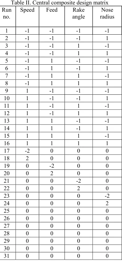
Table II. Central composite design matrix Run
no.
Speed Feed Rake
angle
Nose radius
1 -1 -1 -1 -1
2 -1 -1 -1 1
3 -1 -1 1 -1
4 -1 -1 1 1
5 -1 1 -1 -1
6 -1 1 -1 1
7 -1 1 1 -1
8 -1 1 1 1
9 1 -1 -1 -1
10 1 -1 -1 1
11 1 -1 1 -1
12 1 -1 1 1
13 1 1 -1 -1
14 1 1 -1 1
15 1 1 1 -1
16 1 1 1 1
17 -2 0 0 0
18 2 0 0 0
19 0 -2 0 0
20 0 2 0 0
21 0 0 -2 0
22 0 0 2 0
23 0 0 0 -2
24 0 0 0 2
25 0 0 0 0
26 0 0 0 0
27 0 0 0 0
28 0 0 0 0
29 0 0 0 0
30 0 0 0 0
31 0 0 0 0
While conducting experimentation with molybdenum disulphide assisted hard turning, the amount of molybdenum disulphide powder supplied per unit time to the machining zone is important because an accurate determination of flow rate helps to achieve the desired machining performance. In order to arrive at an optimum flow rate, experiments were conducted to observe the effect of increasing flow rate on the cutting force. Fig. 2 shows the variation of cutting force with flow rate at a cutting speed of 100 min/min, feed of 0.12 mm/rev, 26° effective rake angle and 1.2 mm nose radius in molybdenum disulphide assisted machining. It has been observed from molybdenum disulphide assisted hard turning that the cutting force decreases as the flow rate increases from 1 gm/min to 2 gm/min. After that there is no substantial reduction of the cutting force even if the flow rate has been increased from 2 gm/min to 10 gm/min. The similar trend has been observed for the other cutting conditions. It can be concluded that flow rate of 2 gm/min is sufficient to provide the required lubrication. Hence, in the present investigation, flow rate of molybdenum disulphide powder has been kept at 2 gm/min during the machining of hardened bearing steel.
For the performance study, the experiments were designed using design of experimentation. The design of Adjustable stand
Solid lubricant powder apparatus
[image:2.612.75.262.310.493.2] [image:2.612.65.301.531.692.2]experimentation has a major effect on the number of experiments needed. The most important factors considered for the experimentation and analysis were cutting speed, feed, effective rake angle and nose radius. In order to compare the performance of molybdenum disulphide assisted machining with that of dry hard turning, experiments were conducted considering five levels for each factor as shown in Table I. Central composite rotatable design was employed to reduce the number of experiments to 31 instead of 625 (as per full factorial design). Based on this, 31 experiments were carried out each for dry and molybdenum disulphide assisted hard turning as shown in the design matrix Table II.
The experimental results were used to develop the surface roughness models by Response Surface Methodology (RSM). Response Surface Methodology is a collection of mathematical and statistical techniques that are useful for the modeling and analysis of problems in which response of interest is influenced by several variables and the objective is to optimize the response. The mathematical models commonly used are represented by:
Y = Φ (v, f, α, r) + ε (1) Where Y is the hard turning response, Φ is the response function, and v, f, α, r are the cutting speed, feed, effective rake angle and the nose radius and ‘ ε’ is the error which is normally distributed with zero mean according to observed response. In most of the RSM problems, the form of relationship between the response and the independent variables is not known. Thus, the first step in RSM is to find a suitable approximation for the true functional relationship between the response and the set of independent variables. Usually, a low order polynomial in some region of independent variables is employed. Hence, the first -order linear model between response and other independent variables is modeled as follows:
First order model can be written as:
x
Y
i k i i∑
= + = 1 01
β
β
(2)Where
x
1,x
2 , …x
k are the input variables which influence the responseY
1 . The set of regressioncoefficients
β
’s are unknown parameters and estimated by least squares, and ε is a random error which is normally distributed with zero mean according to observed response. The first-order model is to be appropriate in approximating the true response surface over a relatively small region of the independent variable space in a location where there is a little curvature. Often the curvature in the true response surface is strong enough that the first order model (even with the interaction terms included) is inadequate. The second order model is widely used in response surface methodology for several reasons because (a) the second order is very flexible. It can take on a wide variety of functional forms, so it will work well as an approximation to the true response surface, (b) it is easy to estimate the parameters in the second order model. The method of least squares is used for this purpose and (c) There is considerable practical experience indicating that second-order models work well in solving real response surface problems [15, 16].Second order-model can be written as:
ε
β
β
β
β
+ + + +=
∑
∑
∑ ∑
−= = =
=
x
x
X
X
Y
j k i k j i ij i k i ii i k i i 1 1 2 2 1 1 02
(3) Wherex
1,x
2 , …x
k are the input variables which influence the responseY
2. The set of regression coefficientsβ
’s areunknown parameters and estimated by least squares, and ε is a random error which is normally distributed with zero mean according to observed response.
A computer program was developed in the MATLAB environment, to calculate the value of these coefficients for different responses. The adequacy of the models was tested using the analysis-of-variance technique (ANOVA) [15, 16].
III. RESULTS AND DISCUSSION
During hard turning, lot of heat is generated at the primary deformation zone, secondary deformation zone and maximum temperature is developed at the tool/chip interface which may result in the early cutting tool failure leading to poor quality of the surface produced. Hard turning, employing molybdenum disulphide as a solid lubricant, is a possible environmental friendly alternative for effective control of cutting zone temperature. Hence, in the present work, molybdenum disulphide has been used as solid lubricant to provide the proper lubrication and reduce the friction between the tool and workpiece and thereby reducing heat generation at the tool and workpiece interface.
It has been found in this study that first order models of surface roughness were not adequate. Hence the second order models were developed from the experimental results. The second order surface roughness models developed using response surface methodology for the dry hard turning and molybdenum disulphide assisted hard turning are as follows.
4 3 4 2 3 2 4 1 3 1 2 1 2 4 2 3 2 2 2 1 4 3 2 1 , 2 0713 . 0 1025 . 0 0675 . 0 0075 . 0 0725 . 0 0413 . 0 0540 . 0 0565 . 0 0440 . 0 0515 . 0 1375 . 0 0075 . 0 1117 . 0 1017 . 0 65 . 0 x x x x x x x x x x x x x x x x x x x x Y Dry + − − − − + + + + + − − + − = (4) 4 3 4 2 3 2 4 1 3 1 2 1 2 4 2 3 2 2 2 1 4 3 2 1 , 2 0625 . 0 0938 . 0 06 . 0 0088 . 0 065 . 0 0338 . 0 0486 . 0 0486 . 0 0423 . 0 0511 . 0 12 . 0 0058 . 0 0975 . 0 09 . 0 5557 . 0 2 x x x x x x x x x x x x x x x x x x x x Y MoS + − − − − + + + + + − − + − = (5) Where ‘
Y
2’ is the estimated response of second ordersurface roughness and
x
1,x
2,x
3,x
4 are the coded variablescalculated lack of fits for the second order surface roughness models are less than the tabulated value for the lack of fit at 99% confidence level, which implies that the quadratic models are adequate.
Table III ANOVA for the second order roughness model (dry machining)
Source Sum of squares
d.o.f Mean squares
Fcal F0.01
Model 1.6692 14 0.1192 13.4 3
3.503 Residua
l error 0.1421 16 0.0088 - -
Lack of fit
0.1305 10 0.0130 6.75 7.87 Pure
error
0.0116 6 0.0019
Total 1.8113 30
Table IV ANOVA for the second order surface roughness model (molybdenum disulphide assisted machining) Source Sum of
squares
d.o.f Mean squares
Fcal F0.01
Model 1.3148 14 0.0939 14.20 3.503 Residua
l error 0.1058 16 0.0066 - -
Lack of fit
0.0964 10 0.0096 6.18 7.87 Pure
error
0.0093 6 0.0015 Total 1.4206 30
50
100
150
10 20 30 40
0 0.5 1 1.5 2
Speed (m/min) Feed = 0.12 mm/rev, nose radius = 1.2 mm
Effective rake angle (deg) Su
rf a c e r o u g h n e s s(
μ
m )
0.6 0.7 0.8 0.9 1 1.1 1.2 1.3 1.4 1.5
Fig. 2(a)
50
100
150
10 20 30 40 0.5 1 1.5
Speed (m/min) Feed = 0.12 mm/rev, nose radius = 1.2 mm
Effective rake angle (deg) S
urf a c e r o u g h n e s s(
μ
m )
0.6 0.7 0.8 0.9 1 1.1 1.2 1.3 1.4
Fig. 2(b)
Fig. 2 Interaction effect of cutting speed and effective rake angle on surface roughness in (a) dry hard turning (b) molybdenum disulphide assisted hard turning
15 20
25 30 35
40
0 0.5 1 1.5 2 0.5 1 1.5 2
Effective rake angle (deg) Speed = 100 m/min, feed = 0.12 mm/rev
Nose radius (mm) S
urf ac e r o u g h n es s (
μ
m )
0.6 0.7 0.8 0.9 1 1.1 1.2 1.3 1.4 1.5 1.6
Fig. 3(a)
15 20
25 30
35 40
0 0.5 1 1.5 2 0 0.5 1 1.5 2
Effective rake angle (deg) Speed = 100 m/min, feed = 0.12 mm/rev
Nose radius (mm) S
urf a c e r o u g h n e s s(
μ
m )
0.5 0.6 0.7 0.8 0.9 1 1.1 1.2 1.3 1.4 1.5
[image:4.612.315.541.55.234.2]Fig. 3(b)
[image:4.612.121.530.293.660.2]The mathematical models, given by Equations (4-5), can be used to predict the surface roughness by substituting the values, in coded form, of the respective factors. The responses calculated from these models, for each set of coded variables, can be represented in graphical form and the effect of the different process variables, on the surface roughness, can be interpreted with the help of the graphs.
The variation of surface roughness with respect to cutting speed and effective rake angle can be seen from the Fig. 2. It can be observed from this figure that combination of the cutting speed and effective rake angle is important for achieving the desired values of the surface roughness. Therefore, higher cutting speeds and medium values of effective rake angle are the favorable conditions for the lower values of the surface roughness. The variation of surface roughness with tool geometry parameters i.e. effective rake angle and nose radius can be seen from the Fig. 3. Surface roughness first decreases and then again increases with the increase of effective rake angle. This could be due to the fact that the increase in effective negative rake angle increases the edge strength of the inserts and hence surface finish improves. Further increase in the effective rake angle increases the cutting forces making the machining process difficult and hence the deterioration in surface quality has been observed in the experimental values. It can be concluded that judicious selection of the cutting conditions and the tool geometry is essential in order to produce the quality products in the hard turning. It can be seen that higher values of nose radii combined with the suitable effective rake angles yield good quality surfaces.
Further, it could be seen from the Figs. 2 and 3 that surface roughness values obtained in molybdenum disulphide assisted hard turning were lower as compared to dry hard turning. The substantial reduction in surface roughness by molybdenum disulphide assisted hard turning could be attributed mainly due to the retention of insert sharpness due to lower wear and plastic deformation at reduced temperature. Thus it indicated that the lubricating property of molybdenum disulphide was effective in reducing the rubbing action at the tool-workpiece contact zone. This resulted in lesser wear of the cutting insert, helping it to retain sharpness, which improves surface roughness. Therefore, it can be concluded that molybdenum disulphide assisted hard turning giving better finish in comparison to dry hard turning
IV. CONCLUSIONS
The experimental investigation established that the performance of hard turning could be improved by the presence of molybdenum disulphide at the machining zone. Thus, the use of molybdenum disulphide assisted hard turning leads to improved machinablity with significant improvement in surface quality. Hence, the employment of molybdenum disulphide as a solid lubricant in hard turning process makes the process more attractive and environmental friendly.
REFERENCES
[1] König W., Komanduri R., Tönshoff H.K. and Ackershott G. Machining of hard materials, Annals of the CIRP, 33 (2) , 1984, pp. 417-427 [2] Klocke F., Brinksmeier E. and Weinert K., Capability profile of hard
cutting and grinding processes, Annals of the CIRP, 54 (2), 2005, pp. 557-580
[3] Byrne G. and Scholta E., Environmentally clean machining processes- a strategic approach, Annals of the CIRP, Vol. 42 (1), 1993, pp. 471-474
[4] Klocke F. and Eisenblätter G., Dry cutting, Annals of the CIRP, Vol. 46 (2), 1997 pp. 519-526
[5] Shaji S. and Radhakrishnan V., An investigation on surface grinding using graphite as lubricant, International Journal of Machine Tools and Manufacture, Vol. 42 (6), 2002, pp. 733-740
[6] Shaji S. and Radhakrishnan V., An investigation on solid lubricant moulded grinding wheels, International Journal of Machine Tools and Manufacture, Vol. 43 (9), 2003, pp. 965-972
[7] Gopal, A. V. and Rao, P. V., Performance improvement of grinding of SiC using graphite as a solid lubricant, Materials and manufacturing processes, Vol. 19 (2), 2004, pp. 177-186
[8] Reddy N. S. K. and Rao P. V., Performance improvement of end milling using graphite as a solid lubricant, Materials and manufacturing processes, Vol. 20, 2005, pp. 1-14
[9] Paul S. and Chattopadhay V., Effects of cryogenic cooling by liquid nitrogen jet on forces, temperature and surface residual stresses in grinding steels, Cryogenics, Vol. 35 (8), 1995, pp. 515-523
[10] Paul S. and Chattopadhay V., Effects of cryogenic cooling on grinding forces, International Journal of Machine Tools and Manufacture, Vol. 36, 1996, pp. 63-72
[11] Weinert W., Inasaki I., Sutherland J.W. and Wakabayashi T., Dry machining and minimum quantity lubrication, Annals of the CIRP, Vol. 53 (2), 2004, pp. 511-537
[12] Varadarajan A. S., Philip P.K. and Ramamoorthy B., Investigations on hard turning with minimal cutting fluid application (HTMF) and its comparison with dry and wet turning, International Journal of Machine Tools and Manufacture, Vol. 42 (2), 2002, pp. 193-200
[13] Bhushan B., Modern Tribology Handbook, CRC Press LLC, New York, 2001
[14] Stachowiak G. W. and Batchelor A.W., Engineering Tribology, Butterworth-Heinenann, Woburn, 2001
[15] Myres R.H. and Montgomery D.C., “Response Surface Methodology: Process and Product Optimization Using Designed Experiments” Wiley, New York, 2002
[16] Montgomery D. C “Design and Analysis of Experiments” John Wiley and Sons, New York, 2003
V. NOMENCLATURE v Cutting speed (m/min) f Feed (mm/rev) α Effective rake angle (°)
r Nose radius (mm)
x
1 Coded value for cutting speedx
2 Coded value for feedx
3 Coded value for effective rake anglex
4 Coded value for nose radiusY
Machining responseY
1 Estimated response based on first order modelY
2 Estimated response based on second order modelε Experimental error constant in mathematical model
d.o.f Degree of freedom Fc Tangential cutting force, N