Consistency Maintenance Framework
For Collaborative Software Modelling Tools
Marta Lozano
A dissertation submitted to the University of Dublin, in partial fulfillment of the requirements for the degree of
Master of Science in Computer Science
Declaration
I declare that the work described in this dissertation is, except where otherwise stated, entirely my own work and has not been submitted as an exercise for a degree at this or any other university.
Signed: _________________
Permission to lend and/or copy
I agree that Trinity College Library may lend or copy this dissertation upon request.
Signed: _________________
Acknowledgements
Abstract
The globalization of companies and business, and the improvements in communication and computing have lead to the need of new models of collaborative work. Real-time collaborative editing systems are included in the field of Computer Supported Collaborative Work (CSCW) systems, which allow users to view and design the same document simultaneously from geographically dispersed sites connected by networks.
Distributed Software Engineering (DSE) requires technical knowledge that spans geographical and organizational boundaries. In a distributed environment, developers are dispersed across different sites and even countries. Even thought major contributions have been lately introduced to enable CSCW applications on the Internet to support global collaboration, the area of DSE requires further research.
There are three inconsistency problems that arise in Collaborative Editing Systems: divergence, causal ordering violation and user intentions violation. Divergence can be solved serializing the operations at all sites, causality violation can be solved with a causal ordering communication protocol. However user intention violation solution is dependent on application semantics.
There are few group support framework specialized in DSE, and distributed software modeling. However, we are not aware of any Collaborative Software Modeling Framework using Consistency Maintenance mechanisms where the user intentions are preserved. Current distributed software modeling frameworks address concurrency with traditional methods as locking, turn taking, serialization, etc.
Table of Contents
Chapter 1
Introduction...11
1.1 BACKGROUND... 11
1.2 MOTIVATIONS... 12
1.3 ROADMAP...13
1.3.1 State of the Art...13
1.3.2 Architecture... 14
1.3.3 Concurrency in Collaborative Editing Systems... 14
1.3.4 Consistency Maintenance Framework for Collaborative Software Modelling tools...14
1.3.5 Implementation... 15
1.3.6 Conclusions...15
Chapter 2 State of the Art...16
2.1 CSCW: COMPUTER SUPPORTED COLLABORATIVE WORK...16
2.1.1 Introduction... 16
2.1.2 Classification of CSCW in Time and Place...17
2.1.3 Common CSCW Applications... 17
2.1.3.1 Message Systems ...17
2.1.3.2 Computer Conferencing capabilities... 18
2.1.3.3 Shared diaries and Calendars... 18
2.1.3.4 Bulletin boards ... 18
2.1.3.5 Application Sharing Systems ... 18
2.1.3.6 Collaborative Editing Systems ...18
2.1.4 CSCW Keywords... 19
2.1.4.1 Group Awareness... 19
2.1.4.2 Multi-User interfaces...19
2.1.4.3 Concurrency Control...19
2.2 COLLABORATIVE EDITING SYSTEMS... 20
2.2.1 REDUCE PROJECTS (Real Time Distributed Unconstrained Cooperative Editing)...20
2.2.1.1 GRACE (Graphics Editing System)...21
2.2.1.2 RECIPE (A prototype for Internet-based real-time collaborative Programming). 21 2.3 CONSISTENCY MAINTENANCE FRAMEWORK... 21
2.3.1.1 Definition 1.1. Causal ordering relation ‘’ ... 23
2.3.1.2 Definition 1.2. Dependent and Independent operations ...23
2.3.1.3 Definition 1.3. Intention of an Operation... 23
2.3.1.4 Definition 1.4. A Consistency Model... 23
2.3.2 User Intentions Preservation in Collaborative Graphics Editing Systems... 24
2.3.2.1 Notation... 24
2.3.2.2 Definition 2.1. Conflict Relation ...24
2.3.2.3 Definition 2.2. Compatible relation ☉...25
2.3.3 Accommodating all operation effects... 25
2.4 COLLABORATIONAND SHARINGAMONG UML TOOLS...25
2.4.1 Introduction... 25
2.4.2 XML Metadata Interchange: XMI... 26
2.4.3 Evolution of UML modeling tools: Collaboration and Sharing...27
2.4.4 ArgoUML: Starting point for a Synchronous Collaborative UML Tool Prototype...29
2.4.4.1 ArgoUML supports standards extensively ...29
2.4.4.2 Usability of the UML CASE Tool... 29
2.4.4.3 Unique Generation of ID for networked systems ... 30
Chapter 3 Architecture... 31
3.1 SINGLE-USER SOFTWARE MODELLING TOOL: ARGOUML... 31
3.2 DISTRIBUTING ARGOUML... 32
3.3 THE CONSISTENCY MAINTENANCE COMPONENT...34
3.3.1 Concurrency Detector ...36
3.3.2 Conflict Manager... 36
3.3.3 Conflict Store... 36
3.3.4 Conflict Awareness Presentation ...37
3.4 COMMUNICATION PLATFORM... 37
3.4.1 The Sharing channel ... 37
3.4.2 The Collaboration channel ... 38
3.5 INTEGRATING APPLICATION LAYERWITH COMMUNICATION PLATFORM... 38
3.6 THE TRANSLATION COMPONENT... 39
3.7 THE LATECOMER SUPPORT ... 39
3.8 INTEGRATIONWITH JAVAGROUPS ...40
3.8.1 JavaGroups Support for CSCW...40
3.8.2 Architecture of JavaGroups...41
4.1 INTRODUCTION...44
4.2 CLASSIFICATIONOFOPERATIONSBASEDONCONCURRENCY... 44
4.2.1 Causal ordering relation ... 44
4.2.2 Independent operations. ... 45
4.2.3 Conflict Relation... 45
4.2.4 Definition A.1. UML Semantic Conflict Relation...46
4.2.5 Definition A.2. UML Semantic Compatible Relation... 46
4.2.6 Definition A.3. Equivalent Relation ... 46
4.2.7 Concurrent Cases...46
4.3 CONCURRENCY DETECTION... 47
Chapter 5 Consistency Maintenance Framework for Collaborative Software Modelling tools...51
5.1 INTRODUCTION...51
5.2 INCONSISTENCY PROBLEMSIN COLLABORATIVE EDITING SYSTEMS...52
5.3 APPLICATION SEMANTICSDEPENDENCYFOR CONFLICT MANAGEMENT ...53
5.4 OMG UML SPECIFICATION 1.3 FOUNDATION PACKAGE CORE: ABSTRACT SYNTAX AND WELL -FORMEDNESS RULES...55
5.4.1Association:...55
5.4.2Aggregation... 55
5.4.3Classifier ...56
5.4.4 Feature... 56
5.4.5 GeneralizableElement...57
5.4.6 Namespace...57
5.5 UML RESTRICTION RELATION... 58
5.5.1 Definition B.1 Restriction Relation: OP1 ® OP2... 58
5.5.2 Definition B.2 Restrictive Behavior of an operation OP1... 58
5.6 TIME-LINE DEPENDENCY RELATION... 59
5.6.1 Introduction... 59
5.6.2 Definition C.1. Independent-Behavior Operation... 60
5.6.3 Definition C.2. Dependent-Behavior Operation. ...60
5.6.4Definition C.3. Break Dependencies Behavior. ... 61
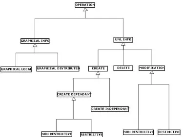
5.7 TYPESOF INFORMATIONINA UML DIAGRAM... 61
5.8 CLASSIFICATION OF CONFLICT OPERATIONS BASED ON APPLICATION DEPENDANT RELATIONS (UML RELATIONS)... 62
5.9DESCRIPTIONOF OPERATIONS CATEGORIES...64
5.9.1Create Independent ... 64
5.9.3 Create Dependent Restrictive:... 65
5.9.4 Modify Non Restrictive: ... 65
5.9.5 Modify Restrictive: ...65
5.9.6 Delete: ... 66
5.9.7 Graphical Local ... 66
5.9.8Graphical Distributed:... 67
5.10 CONFLICT DETECTION MATRIX...67
5.10.1 Conflicts Management...68
5.10.2 Conflict: Modify Non Restrictive Versus Modify Non Restrictive... 70
5.10.3Conflict: Modify Restrictive Versus Modify Restrictive... 70
5.10.4Conflict: Create Restrictive Versus Modify Restrictive...70
5.10.5Conflict: (Create || Modify) Versus Delete...70
5.10.6 Conflict: Create Restrictive Versus Create Restrictive... 70
5.10.7 Conflict: Delete Versus Graphical... 70
5.10.8 Conflict: Graphical Versus Graphical...71
5.11 CONCLUSION...71
Chapter 6 Implementation... 72
6.0.1 Introduction... 72
6.1 NSUML: THE UML MODEL... 73
6.2 GEF MODEL...75
6.3 REAL-TIME COLLABORATION CHANNEL...76
6.4LOCAL OPERATION DISPATCHER...77
6.5 REMOTE OPERATIONS DISPATCHER... 78
6.6 CONFLICTS...79
6.6.1 ConflictManager... 79
6.6.2ConflictStore ... 80
6.6.3UMLConflictType...81
6.7 SHARING CHANNEL...81
6.8 CONFLICT AWARENESS... 82
6.9 COMMUNICATION PLATFORMWITH JAVAGROUPS...82
Chapter 7 Conclusions... 84
7.1 INTRODUCTION...84
7.2 EVALUATION...85
7.3 FUTURE WORK...87
7.3.1 Heterogeneous Collaboration in Software Modeling Tool... 87
Chapter 1
Introduction
1.1 Background
The globalization of companies and business, and the improvements in communication and computing have lead to the need of new models of collaborative work. Real-time collaborative editing systems are included in the field of Computer Supported Collaborative Work (CSCW) systems, which allow users to view and design the same document simultaneously from geographically dispersed sites connected by networks.
Distributed Software Engineering (DSE) requires technical knowledge that spans geographical and organizational boundaries. It has become a need for many organizations. New business models often result in distributed organizations that cannot be physically centralized in one location requiring developers to be dispersed across different sites and even countries.
If software development is viewed as a special case of collaborative editing systems then synchronous collaborative tools are needed to support synchronous work of different developers on the same artifact.
Even thought major contributions have been lately introduced to enable CSCW applications on the Internet to support global collaboration, the area of DSE requires further research.
Distributed software modeling, distributed software development, distributed requirements engineering, distributed project planning, distributed document management, distributed change management, distributed workflow management, software agents for software development… etc, can be included in the field of DSE.
There are few group support framework specialized in DSE, and distributed software modeling. There are very few Collaborative Editing Systems supporting Consistency Maintenance (convergence, causal ordering and user intentions). We are not aware of any collaborative software modeling framework employing Consistency Maintenance mechanisms where the user intentions are preserved. Current distributed software modeling frameworks address concurrency with traditional methods not very appropriate for collaborative work as locking, turn taking, serialization, etc.
The REDUCE (REal-time Distributed Unconstrained Cooperative Editing) project aims to research, develop, and apply innovative technologies for consistency maintenance and
concurrency control in real-time Collaborative Editing systems. Under the REDUCE project Collaborative Text, Graphics and Programming systems have been researched. REDUCE project is actually running in Griffith University, Australia. This has been the main research and ideas source for my thesis. The Consistency Maintenance Framework devised for the Collaborative Graphic Editing System have been modified and extended for supporting Collaborative Software Modeling.
The algorithms and schemas presented in this work have been implemented in the DArgoUML prototype system. DArgoUML is a Distributed version of ArgoUML (a open source Software Modeling tool). A Flexible Consistency Maintenance Framework based on Software Modeling Knowledge has been included in DArgoUML. The Framework can be considered Flexible as it allows the system to maintain temporal inconsistencies, as the shared document versions will merge to a consistent version. Some algorithms have been devised to detect different types of conflicts based on the different levels of inconsistencies they generate. Techniques have been presented to address each specific conflict or level of Inconsistency. Besides a mechanism for conflict group awareness is proposed, where users are aware of other user intentions when concurrent operations do conflict.
1.2 Motivations
As introduced in the previous section, the area of Distributed Software Engineering requires more research. Distributed Software Development is becoming a fact in many organizations however there are few tools that support this collaborative work.
serialization are not very appropriate for collaborative editing system. There are some new techniques for concurrency control more appropriate as operational transformation or multiple object creation. These techniques have been applied mainly to text and graphics environment. One of the main motivations has been the analysis of how these new concurrency control techniques could be applied to applications with richer semantic information, as is software modelling tools. Just to see how the semantics are richer: in a UML model there are two types of information: graphical information and UML information. For the UML information the Abstract syntax and the Well-Formedness rules restrict the behaviour of the possible operations that can be applied to the model.
There are very few collaborative software modelling tools and research projects. The existent ones use traditional methods for concurrency control. DArgoUML extends open source ArgoUML for supporting distribution.
1.3 Roadmap
This section describes briefly each of the remaining chapters contained in this dissertation.
1.3.1 State of the Art
Computer Supported Collaborative Work, CSCW State of the Art is addressed in this Chapter:
In the first section the CSCW concept is explained giving some popular definitions and then the CSCW applications are categorized based on two dimensions, time and place. Some CSCW concepts as Group Management, Concurrency Control mechanisms, etc are introduced.
In the next section some Collaborative Editing Systems that address consistency maintenance are presented.
Finally the State of the art in Software Modelling tools is presented: The standards they use, mechanisms for modelling, the sharing of the UML models and a recent tool and few research projects for real-time cooperation!
1.3.2 Architecture
In this chapter the whole process of extending the single-user open source software modelling tool into a version supporting distribution is presenting. Then the architecture of the Consistency Maintenance component is presented. The next section describes the two channels of communication among collaborating peers: The Sharing channel for transferring the complete application state and the collaboration channel for real-time operations. In the next section the component that translates the operations from/to the network is explained. Latecomer support and the support of JavaGroups for CSCW systems are finally presented.
1.3.3 Concurrency in Collaborative Editing Systems
This chapter has two main sections, the first one is a classification of operations based on their concurrent behaviour, and the second section addresses the issue of concurrency detection.
1.3.4 Consistency Maintenance Framework for Collaborative Software
Modelling tools.
This chapter presents a Flexible Consistency Maintenance framework for Collaborative Software Modelling tools.
First the three inconsistency problems and their solutions are again presented. User Intention violation can not be solved with a generic solution as the other two: divergence and causal ordering violation. For preserving user intentions a solution based on application semantics is devised. In the environment of Software Modelling tools, application semantics includes: UML information, Graphical Information and Restriction Rules based on UML Specification and Time-Line dependencies.
1.3.5 Implementation
This chapter includes the description of the implementation process of the elements described in the architecture chapter.
1.3.6 Conclusions
Chapter 2
State of the Art
2.1 CSCW: Computer Supported Collaborative Work
2.1.1 Introduction.
The globalization of companies and business and the improvements in communication and computing have lead to need of new models of collaborative work (software). In a distributed environment, developers are dispersed across different sites and even countries. CSCW systems enable geographically dispersed participants work together.
CSCW are special Distributed Systems because of the Human Computer Interaction. As result of this Interaction some factors acquire special relevance as Group Awareness, Multi-User interfaces, Concurrency Control and Group Communication and Coordination.
There are many definitions for CSCW and Groupware, some of the most popular are:
Ellis [1]defined Groupware as "Computer-based systems that support groups of people engaged in a common task (or goal) and that provide an interface to a shared environment."
According to Brinck “CSCW is the study of how people work together using computer technology. Typical topics include use of email, hypertext that includes awareness of the activities of other users, videoconferencing, chat systems, and real-time shared applications, such as collaborative writing or drawing." [2]
2.1.2 Classification of CSCW in Time and Place
There are four situations in which groups may work together. This distinction was made first by Johansen [3]. The different types of cooperation arise from the combination of two dimensions: time and place. Regarding with time dimension the communication can be synchronous or asynchronous:
Synchronous Communication or Collaboration: Real- Time systems that allow participants see each other changes immediately. Group of users can cooperate at the “same time”.
Asynchronous Communication or Sharing: Participants cooperate over “different periods of time”. For example a user could edit a document and other user could make some annotations over the document afterwards.
For instance in the field of Software Modelling tools a user could create a UML model. It could be transmitted to another user in XMI format. Second user could update the UML model and send it again to the first user. This would constitute Asynchronous Communication. While in a Synchronous Collaborative Software Modelling tool, several users could model a software system together, and the modifications on the UML elements would be seen immediately by all the collaborators.
2.1.3 Common CSCW Applications
2.1.3.1 Message Systems
Message Systems are email-enabled software applications. These systems use textual messages as interchange format for communicating with group of users. There are several types of message systems:
• Email: Allows the transmission and reception of electronic messages, which consists on various fields including the recipient, sender, subject matter and body of the mes-sage. Email systems provide a framework with functionalities for the creation, view, and management (storage, deletion) of messages, including additional functionalities as attach/insert file to a message. Email is the most well known message system today.
communicating, messages are left in a newsgroup. Any reader belonging to that group can access the messages.
• Chat systems: A system that allows any number of logged-in users to have a typed, real-time, on-line conversation, with other users logged via a network.
2.1.3.2 Computer Conferencing capabilities
Possible, thanks to the increase of communication bandwidth and video compression techniques to allow real-time and sound links between remote sites. Meetings can be arranged among geographically dispersed sites in which participants are able to see and hear each other and thus work together.
2.1.3.3 Shared diaries and Calendars
Provide support for the arrangement and organization of meetings. Group members record their individual appointments and schedules in the electronic diary/calendar. If somebody wants to arrange a meeting all available dates may then be discerned.
2.1.3.4 Bulletin boards
Capabilities for storing messages and files. Discussions may be arranged around topics of interest and anyone with access may read all messages on a particular topic left by others or add messages to the topic. Forums and discussion groups allow users to post messages but don't have the capacity for interactive messaging.
2.1.3.5 Application Sharing Systems
Allow participants to share an ordinary single-user application. (Word processor or spreadsheet). The application run on a workstation.
2.1.3.6 Collaborative Editing Systems
processor), software modeling system. This thesis is about synchronous software modeling system, that allows dispersed users work together in a UML model when designing a software system.
2.1.4 CSCW Keywords
2.1.4.1 Group Awareness
Being aware of other users’ locations, activities, and intentions relative to the task enables people to work together more effectively. There are different types of awareness, for many kinds of systems is very useful to know who is collaborating at some stage in the session, who has done what, what are the future intentions of the users, when there are concurrency conflicts, who are the participants in a conflict and why the conflict has been generated. A shortcoming of an over awareness information may be the violation of users privacy.
2.1.4.2 Multi-User interfaces
Multi-user interfaces are different than single-user interfaces. However that difference should not be very high. In [9] the gap in terms of usability between single-user editor and multi-user editor is presented: Users are forced to learn new Interfaces and new ways of working. The ICT “collaboration Transparency” project aim to transform single-user applications into multi-user applications without changing too much the application code. In a multi-user interface information has to be added in the shape of group awareness so users can cooperate effectively.
In this thesis a single-user application for software modeling has been transformed in a multi-user application. The multi-user interface has hardly changed so the level of usability is high. Besides conflict awareness information has been added to reflect all user intentions.
2.1.4.3 Concurrency Control
2.2 Collaborative Editing Systems
As it has been introduced in 2.1.3.6 Collaborative Editing Systems CES are included in the field of CSCW. CES allow members of a team (that can be dispersed geographically), work on the same document concurrently (real-time).
This section describes an overview of some CES and the mechanisms employed to address concurrency problems
2.2.1 REDUCE PROJECTS (Real Time Distributed Unconstrained
Cooperative Editing)
Variety of collaborative projects, initially REDUCE was focused on Collaborative Text Editing. [17]
A brief overview of some REDUCE projects is presented as for these systems a Consistency Maintenance Framework has been devised, where the three inconsistency problems in a CES are addressed: divergence, causality preservation and user intention violation. Intention preservation property can only be achieved by application dependent mechanisms. So a different mechanism is proposed in text editing and graphics editing.
The work and research done for REDUCE projects have been deeply examined and used as basis for important ideas for this thesis.
For the Text Editing environment an optimistic approach to concurrency control called operational transformation is proposed. The novelty of this schema is that it allows independent operations to be executed in any order but ensures that their final effects are identical and the intentions are preserved. [4]. They show how Intention-Preservation achieved by operational transformation is not achievable by any traditional serialization protocol. User Intention Preservation depends on Application Semantics.
REDUCE collaborative technologies and systems have been applied to other areas as Collaborative Graphic Editing, GRACE, or collaborative programming RECIPE.
2.2.1.1 GRACE (Graphics Editing System)
GRACE is a prototype of a collaborative graphics editing system [18]. In GRACE, a novel mechanism for preserving user intentions has been presented: [5] A Multiple Object Version Scheme. In this scheme when a conflict is detected different versions of the targeted object are created. This schema has the property of minimizing the number of versions created combining properly compatible versions in the same version. GRACE Consistency Maintenance mechanisms are addressed deeply in this chapter in section
2.2.1.2 RECIPE (A prototype for Internet-based real-time collaborative
Programming)
RECIPE [19] is an Internet-based real-time collaborative programming system that allows physically dispersed programmers to concurrently and collaboratively design, code, test, debug and document the same program. [7].
In RECIPE a Hierarchical collaboration schema is presented: The prototype can share the compiling applications, debugging applications or even the entire Unix shell application for collaboration. There are four types of sharable sessions in the RECIPE prototype system, that is Unix shell session, Edition session, Compiling session and Debugging session. RECIPE prototypes uses REDUCE techniques for supporting real time cooperative editing.
2.3 Consistency Maintenance Framework
2.3.1 Achieving Convergence, Causality Preservation and Intention
Preservation in Real-Time Cooperative Editing Systems
“Real-time cooperative editing systems allow multiple users to view and edit the same text/graphic/image/multimedia document at the same time from multiple sites connected by communication networks. Consistency Maintenance is one of the most significant challenges in designing and implementing real-time cooperative systems…” [4].
The cooperative editing systems subject to their research have the following properties:
• Real-time: “Local response is quick (almost as in a single-user application) and independent from network latency, and the latency for reflecting remote actions should be low (dependent on network latency)”
• Distributed: “Cooperating users may reside in different machines connected by different communication networks with non deterministic latency”.
• Unconstrained: “Multiple users are allowed to concurrently and freely edit any part of the document at any time”.
A replicated architecture is proposed as the only solution for accommodating the properties mentioned above especially for good responsiveness and unconstrained behaviour. In a replicated architecture there is no central server, the shared document is replicated at all sites.
“One of the most significant challenges in designing and implementing real-time cooperative editing systems with a replicated architecture is consistency maintenance of replicated documents”
In [4] consistency maintenance model the three inconsistency problems that appear in real-time collaborative editing systems, as well as the properties they violate and their solutions is presented:
• Divergence: ”Operations may arrive and be executed at different sites in different orders, resulting in different final result. Unless operations are commutative final editing results would not be identical among cooperating sites”. The Divergence problem can be solved by any serialization protocol.
• Causality Violation: “Due to the non deterministic communication latency, operations may arrive and be executed out of their natural cause effect order” The causality violation can be solved with a Causal Order Communication Protocol (Causal Order Multicasting).
• User Intention: “Due to concurrent generation of operations, the actual effect of an operation at the time of its execution may be different from the intended effect of this operation at the time of its generation”. User intentions violation can be solved with
application dependant mechanisms.
2.3.1.1 Definition 1.1. Causal ordering relation ‘
’
Given two operations OP1 and OP2, generated at sites I and J, then OP1 OP2 if:
1. I = J and the generation of OP1 happened before the generation of OP2 or 2. I ≠ J and the execution of OP1 happened before than the generation of OP2.
2.3.1.2 Definition 1.2. Dependent and Independent operations
Given two operations OP1 and OP2:
1. OP2 is said to be causally dependent on OP1 if only if OP1 OP2.
2. OP1 and OP2 are said to be causally independent if and only if neither 3. OP1OP2, nor OP2 OP1. It is expressed as OP1 || OP2.
2.3.1.3 Definition 1.3. Intention of an Operation
The Intention of an operation OP1 is the Execution effect, which can be achieved by applying OP1 on the
document state from which OP1 was generated.
2.3.1.4 Definition 1.4. A Consistency Model
A collaborative editing system is said to be consistent if it always maintains the following properties:
a) Convergence: When the same set of operations have been executed at all sites. b) Causality Preservation:For any pair of operations OP1 and OP2, if OP1OP2
then OP1 is executed before OP2 at all sites.
c) Intention Preservation: For any operation OP1, the effects of executing OP1 at all sites are the same as the intention of OP1, and the effect of executing OP1
does not change the effects of independent operations.
2.3.2 User Intentions Preservation in Collaborative Graphics Editing
Systems
User Intention Preservation mechanisms for Collaborative Graphics Editing systems has been examined as these systems can be used for CAD and CASE tools to draw design diagrams, or to draw illustrative figures within documents collaboratively.
Chen and Sun ideas for maintaining consistency in real-time collaborative graphics editing system, [5], have been examined deeply, and considered the starting point for the designing of Consistency Maintenance Framework for Collaborative Software Modelling tools.
As it was stated in the previous section, “the inconsistency problem which needs to be solved is intention violation caused by the execution of conflicting operations”
Chen presents a new mechanism for preserve all users intentions in the Graphics Environment: A Multiple Object Version Scheme. In this scheme when a conflict is detected different versions of the targeted object are created. This schema has the property of minimizing the number of versions created combining properly compatible versions in the same version.
2.3.2.1 Notation
First a notation is introduced to give a precise definition of operation conflict, and following the formal definitions of conflict and compatible relation among operations: [5]
Target (OP1): Object being targeted by the operation OP1.
Property.Type (OP1): Attribute of the object that is targeted by OP1.
Property.Value (OP1): The new value for the attribute to be updated.
2.3.2.2 Definition 2.1. Conflict Relation
Given two operations OP1 and OP2 they conflict with each other OP1 OP2 if:
1. OP1|| OP2.
2. Target (OP1) = Target (OP2)
3. Property.Type (OP1) = Property.Type (OP2).
2.3.2.3 Definition 2.2. Compatible relation
☉
Given two Operations OP1 and OP2, if they do not conflict with each other, they are compatible, expressed as OP1☉OP2.
2.3.3 Accommodating all operation effects
When a conflict is detected how do actual systems accommodate all user intentions:
• Null effect: Neither of the conflictive operations has a final effect on the target object. This can be achieved by rejecting/undoing an operation when it is found to be conflicting with another operation. This Null effect does not preserve any user Intention. The consequence of this intention violation is that, whenever there is a conflict, the work concurrently done by involved users will be destroyed, which is highly undesirable in the collaborative working environment. When a conflict occurs, the involved users are provided with no explicit information about what the other users actions were or intentions might be.
• Single operation effect: Retain the effect of only one operation. This can be achieved by enforcing a serialized effect among all operations. The final results at both users sites are identical. The user Intentions are not preserved and only one user work can be preserved.
• All operations effect, based on multiple versions strategy [17, 102, 100] two versions of the object will be created. In this way the effects of both operations are accommodated in two separate versions. The side effect of this approach is that the single version object may be converted to multiple versions if a conflict occurs.
2.4 Collaboration and Sharing among UML Tools
2.4.1 Introduction
The Unified Modeling Language (UML) [21] isa general-purpose notational language for designing software systems. UML has become the industry standard language for modeling software systems and communication.
Communication is the main benefit about using a standardized language. With UML precise definitions can be constructed, understood, and interchanged among Software Modeling tools and Professionals.
UML CASE tools provide a framework to help designers specify, construct and visualize complex systems using UML. There are many UML tools, to mention a few:
Rational are market leaders in the UML CASE tools .UML was devised by Grady Booch, James Rumbaugh, and Ivar Jacobson within Rational. Rational offers as well a Unified Process (RUP) used throughout the software lifecycle.
TogetherSoft developed one of the first UML CASE tool to be totally integrated with the code. The tool can do reverse engineering obtaining a model from the code.
Cittera supports real-time collaboration so that multiple parties across various geographic locations are able to work together, simultaneously, on the same model.
ArgoUML is an Open Source Development Project and a free UML modeling tool. It has a commercialized extension widely used called Poseidon for UML. (ArgoUML is the starting point for the construction of the Multi-User Synchronous Collaborative Software Modeling Tool, in other words Real-Time Group UML Tool).
2.4.2 XML Metadata Interchange: XMI
When UML first appeared, there was no standard format for interchange of UML models; most individual tools had their own proprietary format.
XMI, the OMG’s XML Metadata Interchange format [20], is a vendor independent format for saving, loading UML models, as well as import/export information from/to other UML tools.
However XMI is a relatively recent standard that is co-evolving and settling down with UML. Different combinations of UML versions and XMI versions exist: only an exact match will enable tool-to-tool interchange. (XMI 1.0, 1.1, UML 1.1, 1.3, 1.4).
A big advantage of XMI being based on XML is that the whole range of generic XML tools is available. In [14] a new perspective for managing UML models is presented using the fact that they are saved into and loaded from XMI format. The main idea is that some tasks are easier to carry over the XMI file instead of over the UML Case tool. For example with the use of an XML parser, the “visibility” of all the “public” attributes of the classes belonging to a package could be changed into “private”. This task could also be performed using UML case tool functionality but it will be slower as it has to be done element by element.
XMI includes only UML information the diagram layout it is lost. In current specifications of UML 1.x, the metamodel definition does not include sufficient details to include graphical and diagram information necessary to represent and interchange the diagrammatic aspects UML models in an interoperable manner. This has resulted in a number of proprietary extensions to UML and by implication proprietary XML/XMI DTDs causing information loss when UML models are exchanged between tools.
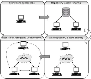
2.4.3 Evolution of UML modeling tools: Collaboration and Sharing.
UML Case tool have evolved from Standalone applications where there were no exchange of information, to Real Time Sharing and Collaboration where tools can not only interchange UML information asynchronously but also they can interact in a Real Time manner.
Standalone tools: No Sharing Information.
Repository-based Model Sharing: The Information can be shared among clients. If the repository is not proprietary the information could be shared among heterogeneous Clients. The Information on the repository is not Real-Time.
Real-Time Model Sharing & Collaboration: The different clients can access not only to the repository Information but they can see as well Real Time operations of the others participants.
Few tools and projects for working in a Real-time Collaborative manner have appeared recently (Cittera [22], Dmeeting [12], The knight Project [13]) however consistency maintenance is achieved with traditional methods that reduce or even avoid concurrency (floor control mechanism, serialization). In these concurrency control mechanisms not more that one user can manipulate the same object at the same time, or with serialization only one-user intentions would be preserved and the operation to be preserved is decided by the system, usually this decision is taken without application dependant information.
A new stage on the evolution of UML CASE tools is needed with Consistency Maintenance mechanisms where all users intentions can be preserved:
[image:28.595.140.453.180.453.2]Real-Time Collaborative tools will generate conflicts when different participants generate conflictive operations. A consistent application dependant mechanism should be used in order to detect, and manage the conflicts generated as result of concurrency.
2.4.4 ArgoUML: Starting point for a Synchronous Collaborative UML Tool
Prototype
These are the reasons for Choosing ArgoUML[23] as starting point for constructing a multi-user UML Case tool:
2.4.4.1 ArgoUML supports standards extensively
Standards: UML 1.3 Specification, XMI, SVG, OCL and others, in this respect, ArgoUML is still ahead of many commercial tools [24]:
• Open Source Project originally developed by a small group of people as a research project
• UML is itself an open standard. ArgoUML use open standards for all its interfaces: The key advantage of open standards is that it permits easy inter-working (in order to avoid fascist systems) between applications, and the ability to move from one application to another as necessary.
• Instead of using a self-implemented UML meta-model, ArgoUML uses a meta-model implementation provided by NovoSoft.
• XML Metadata Interchange (XMI): Is the standard for saving meta-data that make up a particular UML model. In theory this will allow you to take the model you have created in ArgoUML and import it into another tool.
• Graphic Vector Standards: ArgoUML saves diagram layouts using PGML (Portable Graphics Markup Language) an earlier proposed standard than SVG, however the tool has as well functionality for exporting the diagrams in this format. SVG format is to be included in the next versions as format for saving/loading diagram layouts.
2.4.4.2 Usability of the UML CASE Tool
problem is called application sharing or collaboration transparency, in which existing single-user applications are converted into groupware applications.
ArgoUML is a single-user UML CASE tool quite extended. It is a familiar tool, so participants in the new collaborative prototype do not need to employ effort learning new interfaces. The aim is to transform the well-known existing single-user tool into a group tool.
2.4.4.3 Unique Generation of ID for networked systems
Chapter 3
Architecture
3.1 Single-user Software Modelling Tool: ArgoUML
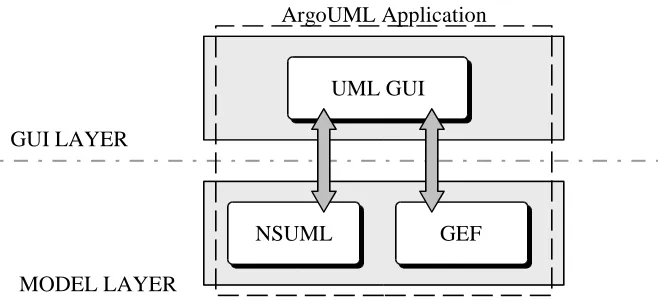
ArgoUML, a single-user software modeling tool is the starting point of the Collaborative Software Modeling prototype. In this section a basic explanation about the architecture of ArgoUML is presented before addressing in following sections the architecture of the collaborative prototype. Figure 3.1 is a basic description of ArgoUML components:
Until now UML Specification does not include graphical information to represent diagram layout. As result of this lack, every UML tool has specific (proprietary) methods for storing graphical Info.
[image:31.595.140.469.335.486.2]UML tools manage two types of information regarding with UML diagrams: UML model and graphical model. The UML model includes all the data related with UML elements, as Class definitions (attributes, operations, modifiers), Interface definitions, Relations definitions (cardinality, aggregation mode). The graphical information necessary to represent those elements in the Graphical User Interface (localization, size..) is included into the graphical model.
Figure 3.1ArgoUML Components
UML GUI
NSUML GEF
GUI LAYER
MODEL LAYER
ArgoUML uses for both UML model and graphical model external implementations:
NSUML: A Complete Implementation of the UML Specification 1.3, NSUML, has been implemented by Novosoft. The implementation is being used by other projects as well. The implementation includes de definition of the UML elements (Classifiers, GeneralizableElements), and the abstract syntax and Well-Formedness rules of the UML Specification.
GEF: Graphical model for representing the UML model. It constitutes the diagram layout. A UML Class Diagram is interpreted as a graph, where the classes and interfaces are nodes, and the relations (associations, generalizations, realizations and dependencies) are edges. It has been implemented by Tigris. OJO references
User interface events update both models:
OP1: CREATE CLASS AT (X, Y): Updates UML model and graph model.
OP2: MOVE CLASS TO (A, B): Updates only graph model.
ArgoUML Application: ArgoUML Graphical User Interface enable users manipulate both UML model and graphical model. ArgoUML stores the UML model in XMI format and graphical model in PGML. However ArgoUML can export the graphical model into SVG format. ArgoUML has functionality added to the User Interface as the Cognitive Support, a mechanism for advising designers about specific solutions based on patterns design.
3.2 Distributing ArgoUML
There is a gap in terms of usability between single-user editors and multiple-user ones. This gap comes from the fact that in multiple-user applications, users are forced to learn new user interfaces. Collaboration Transparency Project [9] aim, is to translate existing single user application into multiple user application without changing the application code.
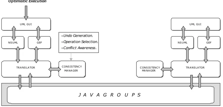
Figure 3.2 shows the components added to transform the single-user application into the multiple-user application.
Figure 3.2Distributing ArgoUML
The architecture is fully distributed, “Replicated Architecture”, there is no central server. The shared data is replicated at all sites.
Replicated Architecture + Optimistic Execution = Fast Response Time
Combining a replicated architecture with an optimistic execution the application will have a fast response time independent of network latency. Optimistic execution means that the events generated locally are executed immediately in the UML and Graphic model, and afterwards the events are sent to the network. The response time is a very important factor in systems with Human Interaction, as the response time has a high influence on the users perception about the quality of the tool.
With a central server and a pessimistic execution the response time is not as fast, and it depends on the latency of the network: from the moment a user generates an event until it appears on the screen some operations occur involving transmission through the network.
J A V A G R O U P S
TRA NS LA TOR TRA NSLATOR UML GUI UML GUI
NS UML
NS UML GEFGEF
TRANSLATOR TRA NS LA TOR UML GUI UML GUI
NSUML
NSUML GEFGEF
CONS ISTENCY MA NA GER CONS ISTENCY
MA NA GER CONS IS TENCYCONS ISTENCYMA NA GER MA NA GER Undo Generation.
Operation Selection. Conflict Awareness.
First the event has to be sent to the server, the server takes a decision, and the server multicast the event to all the collaborators. The user could think the tool is not working very well instead of realizing all the communication process that lies behind.
The only shortcoming of optimistic execution is that the Consistency Maintenance mechanisms are more complicated, as some of the local operations executed immediately may conflict with other concurrent operations generated at other sites concurrently. In some cases some undo or transformation mechanisms will be applied.
The main components that have been added to obtain the distributed architecture are:
Translator: Translate local events into a serializable format to be sent through the network and transforms the remote operations into changes in both local UML and Graphical models.
Consistency Maintenance component: assures the UML model is consistent among all sites.
Communication Platform: Responsible for transmitting all the Real-Time operations, as well as the whole application state for “Latecomer support”.
3.3 The Consistency Maintenance Component
The Consistency Maintenance component assures that the UML model is consistent among all sites these means the consistency maintenance properties are maintained (convergence, divergence and User Intentions). However the consistency model has been designed to be flexible and allow the system to maintain temporal inconsistencies that at some point in time will merge into a unique and consistent version. Always final results will be Consistent.
The Consistency Maintenance component has the following properties:
Fairness of the Resolution: One solution in order to obtain Uniqueness on Conflict resolution could be giving priority to the users based on their network address. (For example: Highest network address highest priority). The resolution is unique but is not fair, in this case the events launched by some user having the highest network address will always prevail over the other users actions. The fairness of the resolution is achieved with application semantics information. There are some solutions:
Rules Engine: deciding which operation/operations will prevail.
Randomly: (For example in some games)
App dependent Priority Levels: In the application the users have assigned a priority level. This priority mechanism is based on application semantics, not like prioritizing based on some non-application semantic information as the network address example mentioned before.
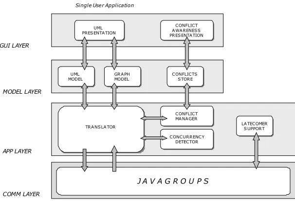
[image:35.595.115.418.481.688.2]The Consistency Maintenance Component for the collaborative prototype has a rule engine to take resolutions in the face of a conflict. The resolution will be unique among all sites.
Figure 3.3Architecture of a Collaborative Peer
J A V A G R O U P S
UML PRESENTATION UML PRESENTATION CONFLICT AWARENESS PRESENTATION CONFLICT AWA RENESS PRESENTATION UML MODEL UML
MODEL GRAPH MODEL GRAPH
MODEL CONFLICTSSTORE CONFLICTS STORE TRANS LATOR TRANSLA TOR CONCURRENCY DETECTOR CONCURRENCY DETECTOR CONFLICT MANA GER CONFLICT MANAGER LATECOMER SUPPORT LA TECOMER S UPPORT GUI LAYER MODEL LAYER APP LAYER COMM LAYER
There are four main subcomponents:
• Concurrency Detector.
• Conflict Manager.
• Conflict Store.
• Conflict Awareness Presentation.
3.3.1 Concurrency Detector
Conflicts can occur only among concurrent operations 4.2.2 Independent operations.. For every operation received the component will detect the set of operations that have a concurrent relation, among the operations received and the local ones (optimistically executed). There are different mechanisms for detecting concurrency. In 4.3 , a concurrency detection mechanism when using total ordering or causal ordering protocols have been proposed.
The set of concurrent operations and possible conflicting ones is examined by the Conflict Manager.
3.3.2 Conflict Manager
The conflict manager consists on a rule engine that detects different types of conflicts and for each conflict type performs a specific resolution. The conflict Manager maintains the Conflict Store Information. Conflict manager rules and resolutions are deeply addressed in 5. Consistency Maintenance Framework.
3.3.3 Conflict Store
3.3.4 Conflict Awareness Presentation
There is conflict awareness information associated with the graphical model and with the UML model. When an element has at least a conflict, its appearance is modified so the collaborators are aware that a conflict has occurred over that element. (In the prototype conflictive elements are marked with a red shadow (the nodes and edges of the graph). If an element is conflictive (red shadow) the conflict information can be consulted (mouse right button). The information appears categorized by property.
3.4 Communication Platform
Peers in the collaborative prototype can communicate with each other over two channels:
3.4.1 The Sharing channel
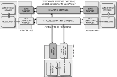
[image:37.595.93.471.491.742.2]Enables the transmission of the application state. The transmission of the whole current UML project occurs at the beginning of each collaborator session: When a newcomer joins the group, it sends a request to one of the members of the group that responds sending the complete UML Project. This newcomer support is known as Latecomer support. [11]
Figure 3.4Communication Architecture
SHARING CHANNEL
SHARING CHANNEL
RT COLLABORATION CHANNEL
RT COLLABORATION CHANNEL SYNC MANAGER SYNC MANAGER DATA OPERATIONS MANAGER DATA OPERATIONS MANAGER NETWORK UNIT TRANSLATOR TRANSLATOR CONSISTENCY MANAGER CONSISTENCY MANAGER SYNC MANAGER SYNC MANAGER DATA OPERATIONS MANAGER DATA OPERATIONS MANAGER NETWORK UNIT TRANSLATOR TRANSLATOR CONSISTENCY MANAGER CONSISTENCY MANAGER SY N C M AN AG ER SY N C M AN AG ER D AT A O PE R AT IO N S M AN AG ER D AT A O PE R AT IO N S M AN AG ER N ET W O R K U N IT TR AN SL AT O R TR AN SL AT O R C O N S IS TE N C Y M AN AG ER C O N S IS TE N C Y M AN AG ER
LATECOMER SUPPORT (XMI files) Unicast Newcomer to Coordinator
The application state is represented in XMI format for the UML model information, and PGML for the diagram layout.
The communication on this channel is unicast and synchronous: unicast meaning that the transmission is between a pair of collaborators (The coordinator of the group, and the newcomer). And synchronous as the newcomer keeps waiting until the reception of the application state.
3.4.2 The Collaboration channel
Used for the transmission/reception of all the real time operations generated by the collaborators during the active Session. So the Translator on each collaborator peer receives the remote events from all other users and propagates them into the local model, and in the same fashion it distributes remotely the local operations.
Users can collaborate working over the same UML Document. The communication in this channel is multicast and asynchronous. All the peers will receive all the events.
3.5 Integrating Application Layer with Communication Platform
The application layer is integrated with the communication platform through networks units on each peer. Each network unit has a DataOperationManager component and a
SynchronizationManager component.
The DataOperationManager is responsible for sending/receiving the Real-Time operations in a asynchronously fashion. The SynchronizationManager is responsible for sending/receiving the complete application state.
Figure 3.5 Integration of Application Layer and Communication Platform
3.6 The Translation Component
The Translation component consists on two main subcomponents: The
LocalOperationsDispatcher and the RemoteOperationsDispatcher.
The LocalOperationsDispatcher translates all the local operations (after optimistic execution) into a serializable format in order to be sent through the network. The DataOperationManager
receives the translated data from the LocalOperationsDispatcher and multicast it to the group.
When the DataOperationManager receives data from the network, the data is passed to the
ConcurrencyDetector, if concurrence is not detected then the RemoteOperationsDispatcher
translates the network data into operations to both models (UML and graphical).
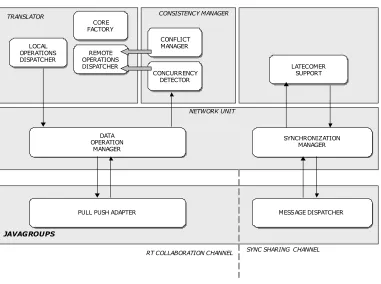
3.7 The Latecomer Support
CONFLICT MANAGER CONFLICT MANAGER TRANSLATOR DATA OPERATION MANAGER DATA OPERATION MANAGER LATECOMER SUPPORT LATECOMER SUPPORT SYNCHRONIZATION MANAGER
PULL PUSH ADAPTER
PULL PUSH ADAPTER MESSAGE DISPATCHERMESSAGE DISPATCHER
NETWORK UNIT
JAVAGROUPS
SYNC SHARING CHANNEL RT COLLABORATION CHANNEL
Latecomer support allows latecomers to join a collaboration session already in progress. When the newcomer joins the session the whole application state is transmitted to its site. Most existed prototypes in synchronous collaboration environment do not support latecomers. All the clients have to start the session at the same time. Otherwise, they may see different stages of the ongoing session. In the real world, the number of users in a collaboration session changes dynamically. This challenge is addressed in [11].
Existing latecomer support mechanisms can be divided in two categories:
Transportation Protocols: “Such as Scalable Reliable Multicast Protocol. All the data packets from the beginning of the session are stored. The late coming application can reconstruct the current state according to the start state and these stored packets. However protocol level algorithms have some disadvantages. First, it is not efficient to transfer all the transport packets because most of the transmission information may be not relevant to the application. Second, some states cannot be reconstructed by using the transport packets”.
Application Level: Latecomer support is implemented with application dependent mechanisms. Most existing solutions are focusing on the application level approach.
Latecomer support for Software Modeling tools can be implemented easily simply transferring the application state in XMI format. In DArgoUML a decentralized approach has been implemented. The newcomer requests the application state to the coordinator of the group. The coordinator of the group is a simple peer.
However with the Consistency Maintenance Framework this simple operation has to be completed sending as well Consistency Maintenance related information as “conflict information” and “undo tables”.
3.8 Integration with JavaGroups
JavaGroups has been used as platform for reliable group communication. It has been selected over other technologies like JXTA as communication platform.
3.8.1 JavaGroups Support for CSCW
Reliability: So that the operations/messages sent by all the users receive the users in a collaborative session. Reliability is necessary to maintain the consistency on the shared document.
Selection of Multicasting Protocol: JavaGroups provides different Multicasting Protocols implementations. So, FIFO, causal ordering, total ordering… can be selected. Thus, two of the three consistency problems (divergence and causal ordering violation) that arise in this types or systems can be easily solved.
The Consistency Maintenance problem left to solve is user intention violation that depends on application semantics and cannot be solved with a generic solution. For solving this problem a Flexible Consistency Framework has been devised based on Software Modeling Knowledge.
Simplicity: It is simple, easy to use and smart. With some basic knowledge about multicasting and sockets, the learning period is very small.
JavaGroups has made easier the process of developing the communication layer. With other technology, external mechanisms for reliability and multicasting ordering should have to be included, and the process likely would not have been so easy. Thanks to JavaGroups!
3.8.2 Architecture of JavaGroups
The participants can join the group, send messages to all members and receive messages from members in the group. The system keeps track of the members in every group, and notifies group members when a new member joins, or an existing member leaves or crashes. A group is identified by its name. Groups do not have to be created explicitly; when a participant joins a non-existing group, that group will be created automatically. The participants of a group can be located on the same host, within the same LAN, or across a WAN. A member can be part of multiple groups.
The architecture of JavaGroups consists on 3 parts:
• The Channel used by application programmers to build reliable group communication applications.
• The Protocol Stack, which implements the properties specified for a given channel.
Channel: To join a group and send messages, a participant on the session has to create a channel and connect to it using the group name. The channel is the handle to the group. While connected, a member may send and receive messages to/from all other participants in the group.
The properties for a channel are specified in a colon-delimited string format. When creating a channel a protocol stack will be created according to these properties. All messages will pass through this stack, ensuring the quality of service specified by the properties.
Building Blocks: Channels are simple and primitive. They provide asynchronous message sending/reception, somewhat similar to UDP. A message sent is essentially put on the network and the send method will return immediately. Conceptual requests, or responses to previous requests, are received in undefined order and the application has to take care of matching responses with requests. Besides the application actively retrieves messages from a channel (pull-style). Building Blocks provide more sophisticated mechanisms on top of a Channel. Applications communicate directly with the building block rather than the channel. The aim of Building Blocks is to save the application programmer from having to write tedious and recurring code, e.g. request-response correlation.
• MessageDispatcher: Provides synchronous (as well as asynchronous) message sending with request-response correlation, e.g. matching responses with the original request. It also offers push-style message reception (by internally using a Push Pull Adapter). The MessageDispatcher can be used in both client and server role: a client sends request and receives responses and a server receives requests and send responses. MessageDispatcher allows a application to be both at the same time.
• PushPullAdapter: This class is a converter between the pull-style of actively receiving messages from the channel and the push-style where clients register a callback, which is invoked whenever a message has been received. Clients of a channel do not have to allocate a separate thread for message reception.
The Protocol Stack: All messages sent and received over the channel have to pass through the protocol stack. Every layer may modify, reorder, pass or drop a message. The composition of the protocol stack for a channel is determined by the creator of the channel: a property string defines the layers to be used (and the parameters for each layer). When creating a channel, the properties of the underlying protocol stack can be specified as argument. A null argument means, use the default composition of layers in the protocol stack. A possible property specification may instruct JavaGroups to create an unreliable, UDP-based channel, another one may specify a loss-less, FIFO channel, and yet a third one may create a loss-less, FIFO, virtually synchronous, total order channel.
• The Sharing Channel has been implemented using a MessageDispatcher component. (See chapter 7. Implementation)
Chapter 4
Concurrency in Collaborative Editing Systems
4.1 Introduction
In this chapter a classification of operations based on causal dependencies is presented. Operations can be concurrent (independent) or causally dependent. Concurrent operations are examined to detect conflicts. Only concurrent operations can conflict.
In the second section a mechanism for detecting concurrent operations is presented.
4.2 Classification of operations based on concurrency
In Synchronous Collaborative Editing Systems several users can generate operations to manage the same shared document. Some of these operations are generated in response to the execution of previous operations; in this case a “Causal Ordering” relation exists among the operation executed previously and the operations generated in response. Some other operations are generated concurrently by users at different sites. Concurrent operations can generate conflicts if they try to modify the same attribute of the same object with different values. In 2.3.1.1Definition 1.1. Causal ordering relation a formal definition of “causal ordering” and “independent” 2.3.1.2Definition 1.2. Dependent and Independent operations relations is presented.
Conflict management mean accommodation of all user intentions. Conflict management and conflict definition are dependant on application semantics. Conflict definition, detection and management for software modeling systems are addressed deeply in 5.Consistency Maintenance Framework.
4.2.1 Causal ordering relation
operations generated by one user at the same site, or if operations are generated at different sites, OP2 was generated after the reception and execution of OP1.
A Formal definition can be found on 2.3.1.1Definition 1.1. Causal ordering relation
4.2.2 Independent operations.
Two operations are said to be independent or concurrent if they both were generated without knowledge of each other. Independent operations do no have “causal ordering relationships” so operations generated on the same site can never be concurrent.
A Formal definition can be found on 2.3.1.2Definition 1.2. Dependent and Independent operations
4.2.3 Conflict Relation
Software Modeling Environment. For a deeply understanding of conflicts examine 5.Consistency Maintenance Framework.
4.2.4 Definition A.1. UML Semantic Conflict Relation
Two operations have a conflict relation if both cannot be executed for one of the following reasons:
1. They try to modify the same attribute of the same object with different values. Only one user intention can be preserved. 2.3.2.2Definition 2.1. Conflict Relation
2. They both cannot succeed because of some restrictions imposed by application dependant rules. UML Restriction Relations, and Time Line Dependency Relations are addressed in 5.Consistency Maintenance Framework
4.2.5 Definition A.2. UML Semantic Compatible Relation
Two operations are compatible if they do not have a conflict relation regarding with Definition A.1. If two operations are compatible all user intentions can be accommodated into the same object.
Compatible operations can be classified into Equivalent and Non-Equivalent operations.
4.2.6 Definition A.3. Equivalent Relation
Two operations are said to be equivalent if their intended effects are the same. So all users intentions could be preserved executing only one of them.
4.2.7 Concurrent Cases
For instance if two users are trying to generate a generalization from class parent to class child, it will only be needed to generate a single generalization, to perform a single operation.
NOTE: Two equivalent operations have the same parameters:
OP1: MODIFY ATTRIBUTE CLASS IS FINAL (Class Id = 1525, “true”).
But if the operations are CREATE operations, the Identifier of the object to be created will be different, as the Identifier is created locally in the site where the operation was generated:
OP1: CREATE ASSOCIATION (Association Id = 15, Client Id = 16, Supplier Id = 17)
OP2: CREATE ASSOCIATION (Association Id = 25, Client Id = 16, Supplier Id = 17)
In the first case any of the two operations can be selected and executed at any site. In the second case the same operation to be executed has to be selected at all sites, otherwise the new created generalization would have different identifiers in different sites and future operations would succeed in some sites whether it would fail in others leading to inconsistencies in the model.
4.3 Concurrency Detection
Several tasks should be performed in order to manage Conflictive User Intentions in a Collaborative System:
• Detecting concurrency: Among the set of operations received, detect which of them are causally dependent and which are concurrent.
• Detecting conflict relations among concurrent operations addressed in 5.Consistency Maintenance Framework.
• Mechanisms for resolving/managing each type of detected conflict addressed in 5.Consistency Maintenance Framework
As it has been said before in this chapter, two operations are concurrent if they were generated without the knowledge of each other. Operations generated by the same user are never concurrent. So, concurrent operations can only be generated in different machines.
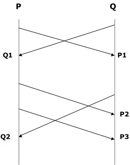
Figure 4.1Concurrent Operations
In the figure operations Q1 and P1 are concurrent; Q2 is concurrent with P2 and P3. Q2 depends on the execution of P1 and Q1. This can be expressed in a formal way according with 2.3.1.1Definition 1.1. Causal ordering relation and 4.2.2Independent operations.
a) Q1 || P1
b) Q2 || P2, Q2 || P3, P3 P2 c) Q2 Q1, Q2 P1.
d) P2 Q1, P2 P1
The communication platform employed for constructing the systems is JavaGroups. With JavaGroups the protocol stack that will be used in the communications can be configured, in this way, the multicasting algorithm, reliability mode… etc can be selected.
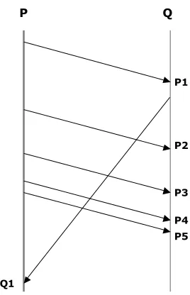
For the Collaborative Editing system, at least a causal ordering multicasting algorithm is needed. JavaGroups provides even a total ordering multicast channel that includes causal ordering. Total ordering indicates that the same causal ordering will be received at all sites [16]. With total ordering concurrency could be detected:
ID (OP1): Each operation has a Unique Identifier along all sites.
DependsOn (OP1): Each operation knows which was the last operation received in the site where it was generated. (last operation received in the site or executed locally in the site).
P Q
Q1 P1
Q2
P2
With this information the state in which an operation was generated can be known. As there is a total ordering among all sites, the set of concurrent operations for OP1 are those operations received at sites between the reception of DependsOn (OP1), and the reception of OP1.