Abstract—The influence of flow arrangement on the heat
transfer behaviors was carried out for a microchannel heat exchanger. The results were obtained by both numerical simulations and experimental data. The solver of numerical simulations – COMSOL – was developed by using the finite element method. For all cases done in this study, the heat flux obtained from the counter-flow arrangement is always higher than that obtained from the parallel-flow one: the value obtained from the counter-flow is 1.1 to 1.2 times of that obtained from the parallel-flow. This means that the heat transfer behaviors of the microchanel heat exchanger with counter-flow are better than those with parallel-flow. For the case of the counter-flow, the experimental results indicated
that the total heat flux of 17.81 W/cm2 was achieved for water
from the hot side of the device having the inlet temperature of 70 ºC and flow rate of 0.2321 g/s and for water from the cold side having the inlet temperature of 22.5 ºC and flow rate of 0.401 g/s. Besides, the numerically obtained profiles of the temperature and the temperature gradient were shown graphically. Furthermore, the results obtained from the numerical analyses were in good agreement with those obtained from the experiments, with the discrepancies of the heat transfer coefficient estimated to be less than 10 %.
Index Terms—heat transfer behavior, micro heat exchanger,
simulation, temperature profile.
I. INTRODUCTION
Heat transfer in microchannels has been an attractive area of study for the last decade. A review of micro heat exchanger related issues such as flow physics, fabrication methods, and applications was done by Bowman and Maynes [1]. This review firstly introduced the experimental and numerical investigations of microchannel flow. Friction and heat transfer measurements of gas flow and liquid flow were discussed in the paper. The paper indicated that the transition Reynolds number is a function of surface roughness and channel geometry. Moreover, in the paper, the heat exchanger designs – including their comparison
Manuscript received December 28, 2009.
Thanhtrung Dang is with the Department of Mechanical Engineering, Chung Yuan Christian University, Taiwan, on leave from Department of Heat and Refrigeration Technology, Ho Chi Minh City University of Technical Education, Ho Chi Minh City, Vietnam (phone: +88632654328; e-mail: [email protected])
Jyh-tong Teng is with the Department of Mechanical Engineering, Chung Yuan Christian University, Taiwan (corresponding author to provide phone: +88632651700; fax: +88632651729; e-mail: [email protected])
and optimization – were also reviewed. Furthermore, several fabrication methods including micromachining, chemical etching, laser machining, electroplating, and lamination, were discussed.
Review of experimental results concerning single-phase convective heat transfer in microchannels was presented by Morini [2]. Additional review results were obtained for the friction factor, the laminar-to-turbulent transition, and the Nusselt number in channels having a hydraulic diameter less than 1 mm. In many cases the experimental data of the friction factor and the Nusselt number in microchannels disagree with those obtained from the conventional theory, but they also appear to be inconsistent with one another.
Peng and Peterson [3] studied the convective heat transfer and flow friction for water flow in microchannel structures. The results indicated that the geometric configuration has a significant effect on the single-phase convective heat transfer and flow characteristics. The laminar heat transfer was found to be dependent upon the aspect ratio and the ratio of the hydraulic diameter to the center-to-center distance of the microchannels.
Brandner et al. [4] described microstructure heat exchangers and their applications in laboratory and industry. Several micro heat exchangers were introduced: polymer microchannel heat exchanger with aluminum separation foil, electrically powered lab-scale microchannel evaporator, ceramic counter-flow microstructure heat exchanger, etc. Ameel et al. [5] presented an overview of the miniaturization technologies and their applications to energy systems. Based on the MEMS technologies (silicon-based micromachining, deep X-ray lithography, and the micro mechanical machining), processes were discussed in the context of applications to fluid flow, heat transfer, and energy systems.
Wei [6] fabricated a stacked microchannel heat sink using microfabrication techniques. Experiments were conducted to study thermal performance of the stacked microchannel structure; overall thermal resistance was less than 0.1 K/W for both counter-flow and parallel-flow configurations. For low volumetric flow rates, the parallel-flow configuration has lower overall thermal resistance compared with that of the counter-flow configuration; however, at high volumetric flow rates for counter-flow and parallel-flow configurations, their overall thermal resistances are indistinguishable. The volumetric flow rate ratio between the top and bottom layers could be optimized to achieve high efficiency. Hasan et al. [7] evaluated the effect of size and shape of channels of a
Numerical and Experimental Studies of the
Impact of Flow Arrangement on the Behavior of
Heat Transfer of a Microchannel Heat Exchanger
Thanhtrung Dang and Jyh-tong Teng
IAENG International Journal of Applied Mathematics, 40:3, IJAM_40_3_12
counter-flow microchannel heat exchanger by using numerical simulation. The effect of shapes of the channels was studied for different channel cross-sections such as square, circular, rectangular, iso-triangular, and trapezoidal shapes. The effect of various channels shows that the circular microchannels give the best overall performance, with the second best overall performance achieved by the square microchannels. By increasing the number of channels in a microchannel heat exchanger, the heat transfer is enhanced while the pressure drop is increased also.
A study on the simulations of a trapezoidal shaped micro heat exchanger was presented by Dang et al. [8]. Using the geometric dimensions and the flow conditions associated with this micro heat exchanger, a total heat flux of 13.6 W/cm2 was achieved by numerical method. Besides, for this microchannel heat exchanger, the heat transfer and fluid flow behaviors in terms of the temperature profile, velocity field, and Reynolds number distribution were determined. Effect of flow arrangement on the heat transfer behaviors of a microchannel heat exchanger was presented by Dang et al. [9]. For all cases done in the study, the heat flux obtained from the counter-flow arrangement is always higher than that obtained from the parallel-flow one. Dang and Teng [10] studied effect of the substrate thickness of counter-flow microchannel heat exchangers on the heat transfer behaviors. It was found that the actual heat transfer rate varies insignificantly with the substrate thicknesses varying from 1.2 to 2 mm. Dang et al. [11] presented an experimental study of the effects of gravity on the behaviors of heat transfer and pressure drop of a microchannel heat exchanger. The results show that in microchannel heat exchanger the influence of gravity on these behaviors is negligibly small.
For the present study, single-phase heat transfer phenomena obtained from experimental data and numerical simulations for a rectangular-shaped microchannel heat exchanger were investigated [9]. In the following sections, two cases will be discussed for this heat exchanger: (1) the counter-flow arrangement and (2) the parallel-flow arrangement.
NOMENCLATURE
A cross-sectional area m2
c specific heat J/(kgK)
cp specific heat at constant pressure J/(kgK)
k overall heat transfer coefficient W/(m2K)
m mass flow rate kg/s NTU number of transfer unit
p pressure Pa
p0 pressure at the outlet Pa
q heat flux W/m2
Qc heat transfer rate of the cold side W
Qh heat transfer rate of the hot side W
Qi internal heat generation W/m3
Qloss heat loss rate W
Re Reynolds number
T temperature ºC
u velocity in the x-direction m/s
v velocity in the y-direction m/s
w velocity in the z-direction m/s
Greek symbols
actual effectiveness
density kg/m3 dynamic viscosity kg/(ms) effectiveness (NTU method)
lm
T
log mean temperature difference ºC thermal conductivity W/(mK)
II. METHODOLOGY
A. Mathematical model
The governing equations in this system consist of the incompressible Navier-Stokes equations for the motion of fluid and the energy equation for transfer of heat [12], [13]. The incompressible Navier-Stokes equations can be expressed by
u/ t + (u
.
)u =.
[-pI + (u + (u)T)] + F(1)
and
.
u = 0 (2)For steady-state conditions, u/ t = 0; the boundary conditions of inlet flow are u = 0, v = 0, and w = w0; the boundary conditions of outlet flow are (u + (u)T)n = 0
and p = p0, where is dynamic viscosity, is density, u is
velocity field, u is velocity in the x-direction, v is velocity in the y-direction, w is velocity in the z-direction, p is pressure,
p0 is pressure at the outlet, I is the unit diagonal matrix, and
F is force per unit volume (Fx= Fy = Fz= 0 N/m 3
). For the energy transport, the walls have no-slip conditions for velocity and temperature at the walls; these conditions are expressed by uwall= 0 and Twall= Tfluid at wall, respectively, where Twall is wall temperature.
The heat transfer equation for the energy transport within the fluid is:
Cp T/ t +
.
(- T) = Qi - Cpu.
T (3)For steady-state conditions, T/ t = 0; the boundary condition of inlet flow is T = T0; the boundary condition of outlet flow is convective flux, expressed by n
.
(- T) = 0; the thermal boundary condition of the bottom and top walls of the microchannel heat exchanger are assumed to be constant heat flux, expressed by -n.
(- T) = q0; and the four side-walls are insulated thermally, expressed by n.
q = 0, where heat flux q = - T + CpTu, T is temperature, cp is specific heat at constant pressure, Qi is internal heat generation, and is thermal conductivity.The energy balance equation for the counter-flow microchannel heat exchanger is expressed by:
Qh - Qloss = Qc = Q (4) Or mhch(Th,i – Th,o) = mccc (Tc,o – Tc,i) (5) where Qh is heat transfer rate of the hot side, Qc is heat transfer rate of the cold side, Q is actual heat transfer rate,
Qloss is heat loss rate from the heat exchanger to the ambient,
m is mass flow rate (subscripts h and c stand for the hot side and cold side, respectively), c is specific heat, Th,i, Th,o, Tc,i and Tc,o are inlet and outlet temperatures of the hot and cold side, respectively, and is actual effectiveness.
The maximum heat transfer rate, Qmax is evaluated by
IAENG International Journal of Applied Mathematics, 40:3, IJAM_40_3_12
Qmax = (mc)min(Th,i – Tc,i) (6) The effectiveness (NTU method) is determined by
max
Q Q
(7)
Heat flux is calculated by
Q q
A
(8)
Or q = kTlm, (9)
where q is heat flux, A is heat transfer area, k is overall heat transfer coefficient, and Tlmis log mean temperature difference.
The log mean temperature difference is calculated by
max min
max
min
ln
lm
T T
T
T T
(10)
B. Design and fabrication
Three major parts are used in the experimental system: the test section (the microchannel heat exchanger), syringe system, and overall testing loop, as shown in Fig. 1. This microchannel heat exchanger can be used to cool electronic devices or for other cooling applications. The heat transfer process of this device is carried out between two liquids (hot and cold water); for two cases studied, the hot and cold fluids are flowing in the opposite and in the same directions.
Fig. 1. Schematic of the test loop for microchannel heat exchanger
Fig. 2 shows the dimensions of the test section. The material for the heat exchanger is aluminum, used as a substrate with the thermal conductivity of 237 W/(mK), density of 2,700 kg/m3, and specific heat at constant pressure of 904 J/(kgK). The thickness of this substrate is 1.2 mm. The top side for the hot water channel has 10 microchannels and the bottom side for the cold water channel also has 10 microchannels. The length of each microchannel is 32 mm. Microchannels have a rectangular cross-section with width of 500 m and depth of 300 m, resulting in a corresponding hydraulic diameter of 375 m. The distance between two microchannels is 500 m. All channels are connected by a manifold for each inlet and
[image:3.612.309.541.126.325.2]outlet of hot water and cold water, respectively. The manifolds have a rectangular shape with the width of 3 mm and the depth of 300 m. To seal the microchannels, two layers of PMMA (polymethyl methacrylate) are bonded on the top and bottom sides of the substrate by UV (ultraviolet) light process, as shown in Fig. 3.
Fig. 2. Dimensions of the test section
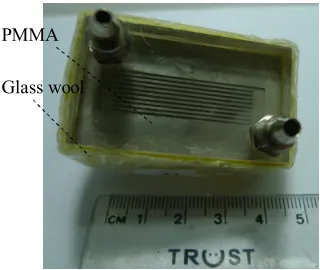
Fig. 3 shows a photo of the microchannel heat exchanger. The test section was manufactured by precision micromachining [5]. Two PMMA plates were bonded on the top and the bottom of the substrate. Each inlet and outlet of this heat exchanger has cross-sectional area of 9 mm2. The four sides of the heat exchanger were thermally insulated by the glass wool with a thickness of 5 mm. The physical properties of the PMMA and the glass wool are listed in Table 1.
Fig. 3. A photo of the microchannel heat exchanger
TABLE1
THE PHYSICAL PROPERTIES OF PMMA AND GLASS WOOL
Water tank
Exhaust air valve
Pre-heater Heater
Buffer tank Pump
P
Balance
Micro heat exchanger
T T
P T
Balance Pump Buffer
tank
PMMA Glass wool
Material Density kg/m3
Thermal conductivity W/(mK) PMMA 1420 0.19 Glass wool 154 0.051
1.2 mm
8.5 mm
26.5 mm
500 m 300 m
Cross-sectional view A-A
46 mm 32 mm 3 mm
9.5mm 14 mm
26.5 mm A
A
Microchannels
Manifold Substrate
IAENG International Journal of Applied Mathematics, 40:3, IJAM_40_3_12
[image:3.612.335.495.491.626.2]C. Numerical simulations
Numerical study of the behavior of the microchannel heat exchanger with 3D single-phase heat transfer was done by using the COMSOL Multiphysics software, version 3.5. The algorithm of this software is based on the finite element method. The generalized minimal residual (GMRES) method was used to solve for the present case [13]. For this study, water was used as the working fluid. No internal heat generation is allowed, resulting in Qi= 0. Nodalization of this model was done by using 26,151 mesh elements; the number of degrees of freedom was 76,411; a relative tolerance was 10-6.
III. RESULTSANDDISCUSSION
A. Numerical results
For the experiments carried out in this study, the inlet temperature and the mass flow rate of the cold side were fixed at 22.5 ºC and 0.2043 g/s, respectively. For the hot side, the mass flow rate was fixed at 0.2321 g/s and the inlet temperatures were varying from 45 to 70 ºC [9]. The thermal boundary conditions of the top and bottom walls of the heat exchanger are assumed to be constant heat flux. The convective heat transfer coefficient between the wall and the ambient used for this solver was 10 W/(m2K) [12]. The
[image:4.612.86.511.217.361.2]a) Counter-flow b) Parallel-flow Fig. 4. The temperature profile of the microchannel heat exchanger
a) Counter-flow
b) Parallel-flow
Fig. 5. The profiles of temperature gradients of the microchannel heat exchanger
IAENG International Journal of Applied Mathematics, 40:3, IJAM_40_3_12
[image:4.612.164.449.402.718.2]temperature profile of the microchannel heat exchanger is shown in Fig. 4 for the inlet temperature of 45 ºC at the hot side. Fig. 4a and Fig. 4b show the temperature profiles for the cases with counter-flow and parallel-flow at the conditions specified above.
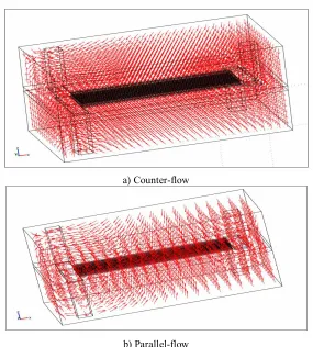
Profiles of the temperature gradients shown in Fig. 5 indicate the temperature gradients from heat exchanger’s cold region towards its hot region, with Fig. 5a being the counter-flow and Fig. 5b being the parallel-flow. The profiles of the temperature gradients in these three planes (x-y, y-z, and z-x planes) were shown in more detail in [11]. Distribution of the temperature gradients varies along the channel length of the heat exchanger with counter-flow and parallel-flow configurations. In the middle of the heat exchanger with counter-flow arrangement, the temperature gradients are in fishbone shapes. However, the temperature gradients are in the perpendicular direction towards the substrate of the heat exchanger with parallel-flow arrangement.
At the conditions stated above, a relationship between the counter-flow and the parallel-flow cases for the outlet temperatures (for both the hot side and cold side) and the inlet temperature of the hot side is shown in Fig. 6a. The outlet temperatures increase as the inlet temperature of the hot side increases. For the counter-flow case, the outlet temperature of the cold side is higher than that obtained at the hot side. However, for the parallel-flow case, the outlet temperatures of the cold side are lower than or equal to those obtained at the hot side. As a result, at a specified condition, the heat flux obtained from the counter-flow arrangement is higher than that obtained from the parallel-flow arrangement of the microchannel heat exchanger. Fig. 6b shows the comparisons of the heat fluxes between the counter-flow and parallel-flow cases.
B. Experimental results
Under the constant room temperature condition of 24 ºC, experimental data associated with the microchannel heat exchanger were obtained. For this study, deionized water was used as the working fluid. Equipments used for the experiments are listed as follows:
1. Thermocouple wires: Model PT-100, made by Omega 2. Pump for the cold side: Model VSP-1200, made by
Tokyo Rikakikai
3. Pump for the hot side: Model PU-2087, made by JASCO 4. Heater: Model AXW-8, made by Medilab
5. Differential pressure transducer: Model PMP4110, made by GE Druck
6. Micro electronic balance: Model TE-214S, made by Sartorious.
TABLE 2
ACCURACIES AND RANGES OF TESTING APPARATUSES
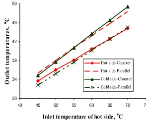
[image:5.612.138.472.72.216.2]Accuracies and ranges of testing apparatus are listed in Table 2. At the condition stated above, the inlet temperature and the mass flow rate of the cold side were fixed at 22.5 ºC and 0.2043 g/s, respectively. For the hot side, the mass flow rate was fixed at 0.2321 g/s and the inlet temperatures were varying from 45 to 70 ºC [9]. A relationship of the experimental results between the counter-flow and the parallel-flow cases for the outlet temperatures (for both the hot side and cold side) and the inlet temperature of the hot side is shown in Fig. 7. The outlet temperatures also increase as the inlet temperature of the hot side increases.
30 34 38 42 46 50
40 45 50 55 60 65 70 75
Inle t te mpe rature of hot side , oC
O
u
tl
e
t
te
m
p
e
r
a
tu
r
e
s,
oC
Hot side-Counter
Hot side-Parallel
Cold side-Counter
Cold side-Parallel
Fig. 7. A comparison of the experimental results between the counter-flow and parallel-flow for outlet
temperatures of both sides Testing apparatus Accuracy Range
Thermocouple 0.1 0~100 oC
Differential pressure transducer 0.025% FS 0~1 bar Precision balance 0.0015 g 0.0000~220 g
30 34 38 42 46 50
40 45 50 55 60 65 70 75
Inlet temperature of hot side, oC
O
u
tl
e
t
te
m
p
e
r
a
tu
r
e
s,
oC
Hot side-Counter
Hot side-Parallel
Cold side-Counter
Cold side-Parallel
0 2 4 6 8 10 12 14 16
40 45 50 55 60 65 70 75
Inlet temperature of hot side, oC
H
e
a
t
fl
u
x
,
W
/c
m
2
Counter-flow
Parallel-flow
a) Outlet temperatures b) Heat fluxes
Fig. 6. A comparison between the counter-flow and parallel-flow cases
IAENG International Journal of Applied Mathematics, 40:3, IJAM_40_3_12
[image:5.612.348.495.578.700.2]For the counter-flow case, the outlet temperature at the cold side is higher than that obtained at the hot side. However, for the parallel-flow case, the outlet temperature at the cold side is lower than that obtained at the hot side. As a result, the heat flux obtained from the counter-flow arrangement is higher than that obtained from the parallel-flow arrangement of the microchannel heat exchanger, as shown in Fig. 8a. Since the heat flux obtained from the simulation is only slightly higher than that obtained from the experiment, the results obtained from the simulation are judged to be in good agreement with those obtained from the experiments. The maximum difference of the heat flux is 1.174 W/cm2; it occurs at high inlet temperature of the hot side for the parallel-flow arrangement, and the maximum percentage error is 9.7%.
When the inlet temperature of the hot side is increased, the heat transfer rate Q of the heat exchanger increases also. As a result, the heat transfer result obtained from the effectiveness (NTU method) increases with rising inlet temperature at the hot side, as shown in Fig. 8b. The figure shows a comparison between numerical and experimental results of the effectiveness (NTU method) for the microchannel heat exchanger with counter-flow. The maximum difference of the effectiveness is 0.009; it occurs at low inlet temperature of the hot side, and the maximum percentage error is 1.6%.
30 34 38 42 46 50
0.1500 0.2000 0.2500 0.3000 0.3500 0.4000 0.4500
Mass flow rate of cold s ide, g/s
O
u
tl
e
t
te
m
p
e
r
a
tu
r
e
s,
oC
Hot side-Count er
Hot side-Parallel
Cold side-Counter
[image:6.612.141.466.57.204.2]Cold side-Parallel
Fig. 9. A relationship between the outlet temperatures and the mass flow rates of the cold side
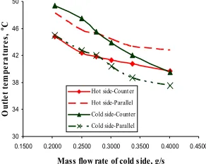
At another experimental condition, for the experiments done in this study, the inlet temperature and the mass flow rate of the hot side were fixed at 70 ºC and 0.2321 g/s, respectively. For the cold side, the inlet temperature was fixed at 22.5 ºC and the mass flow rates were varying from 0.2043 to 0.401 g/s. Fig. 9 shows a relationship between the outlet temperatures (for both the hot side and cold side) and the mass flow rates of the cold side at the condition stated above with two flow arrangements (counter-flow and parallel-flow). The outlet temperatures are also a function of the mass flow rate at the cold side. Contrary to the case of varying inlet temperature of the hot side, the outlet temperatures decrease as the mass flow rate of the cold side increases. For the counter-flow case, the outlet temperature of the cold side is higher than or equal to that obtained at the hot side. However, for the parallel-flow case, the outlet temperature at the cold side is lower than that obtained at the hot side. As a result, for the microchannel heat exchanger, the heat flux obtained from the counter-flow arrangement is higher than that obtained from the parallel-flow arrangement, as shown in Fig. 10.
0 4 8 12 16 20
0.1500 0.2000 0.2500 0.3000 0.3500 0.4000 0.4500
Mas s flow rate of cold s ide g/s
H
e
a
t
fl
u
x
,
W
/c
m
2
Counter-flow
[image:6.612.352.498.505.622.2]P arallel-flow
Fig. 10. A relationship between the heat flux and the mass flow rates of the cold side
5 7 9 11 13 15
40 45 50 55 60 65 70 75
Inlet temperature of hot side, oC
H
e
a
t
fl
u
x
,
W
/c
m
2
Num. results of counter-flow
Exp. results of counter-flow
Num. results of parallel-flow
Exp. results of parallel-flow
0.5 0.52 0.54 0.56 0.58 0.6
40 45 50 55 60 65 70 75
Inlet temperature of hot side, oC
E
ff
e
c
ti
v
e
n
e
ss
(
N
T
U
m
e
th
o
d
)
Num. results of counter-flow Exp. results of counter-flow
[image:6.612.109.255.578.694.2]a) Heat flux b) Effectiveness (NTU method) Fig. 8 A comparison between numerical and experimental results
IAENG International Journal of Applied Mathematics, 40:3, IJAM_40_3_12
IV. CONCLUSION
Experimental work and numerical simulations (using 3D COMSOL software package) were done for the microchannel heat exchanger with rectangular channels having hydraulic diameter of 375 m for two cases (counter-flow and parallel-flow). Heat transfer behaviors of the single-phase fluid inside the microchannel were determined.
The heat flux of 17.81×10⁴ W/m2 (or 17.81 W/cm2) was achieved for water from the hot side of the device having the inlet temperature of 70 ºC and mass flow rate of 0.2321 g/s and for water from the cold side having the inlet temperature of 22.5 ºC and mass flow rate of 0.401 g/s.
With all cases done in this study, the heat flux obtained from the counter-flow is always higher than that obtained from the parallel-flow. As a result, the microchannel heat exchanger with counter-flow should be selected to use for every case (except few special cases).
In this study, good agreements were achieved for comparisons of the behaviors of heat transfer between the results obtained from numerical simulations and experimental data for the fluid for the microchannel heat exchanger used in this study, with the maximum percentage difference between the two results of less than 10%.
ACKNOWLEDGMENT
The authors would like to thank all members of the Thermo-Fluidic Analysis Group (TFAG) Lab at Department of Mechanical Engineering, Chung Yuan Christian University. Helps provided by them for us to carry out the research in this paper are gratefully acknowledged. In addition, the supports of this work by a research grant from National Science Council of Republic of China in Taiwan (Grant No. NSC 96-2221-E-033-039) and by a project of the specific research fields in the Chung Yuan Christian University, Taiwan, under grant CYCU-98-CR-ME are deeply appreciated.
REFERENCES
[1] W.J. Bowman, D. Maynes, A review of micro-heat exchanger flow physics, fabrication methods and application, Proceedings of ASME IMECE 2001, New York, USA, Nov 11-16, 2001, HTD-24280, pp. 385-407
[2] G.L. Morini, Single-phase convective heat transfer in microchannels: a review of experimental results, International Journal of Thermal Sciences, Volume 43, Issue 7, July 2004, pp. 631-651
[3] X.F. Peng and G.P. Peterson, Convective heat transfer and flow friction for water flow in microchannel structures, International J. Heat Mass Transfer 39, 1996, pp. 2599–2608
[4] J.J. Brandner, L. Bohn, T. Henning, U. Schygulla and K. Schubert, Microstructure heat exchanger applications in laboratory and industry, Proceedings of ICNMM2006, Limerick, Ireland, June 19-21, 2006, ICNMM2006-96017, pp. 1233-1243
[5] T.A. Ameel, R.O. Warrington, R.S. Wegeng and M.K. Drost, Miniaturization technologies applied to energy systems, Energy Conversion and Management, 38 (1997), pp. 969–982
[6] X. Wei, Stacked microchannel heat sinks for liquid cooling of microelectronics devices, Ph.D. thesis, Academic Faculty, Georgia Institute of Technology, 2004
[7] M.I. Hasan, A.A. Rageb, M. Yaghoubi, H. Homayoni, Influence of channel geometry on the performance of a counter flow microchannel heat exchanger, International Journal of Thermal Sciences, Volume 48, Issue 8, Aug 2009, pp. 1607-1618
[8] T.T. Dang, Y.J. Chang and J.T. Teng, A study on the simulations of a trapezoidal shaped micro heat exchanger, Journal of Advanced Engineering, Volume 04, No. 4, Oct 2009, pp. 397-402
[9] T.T. Dang, J.T. Teng, and J.C. Chu, Effect of flow arrangement on the heat transfer behaviors of a microchannel heat exchanger, Lecture Notes in Engineering and Computer Science: Proceedings of The International MultiConference of Engineers and Computer Scientists 2010, IMECS 2010, 17-19 March, 2010, Hong Kong, pp. 2209-2214
[10] T.T. Dang and J.T. Teng, Effect of the substrate thickness of counter-flow microchannel heat exchanger on the heat transfer behaviors, Proceedings of the international symposium on computer, communication, control and automation 2010, Taiwan, May 2010, pp. 17-20
[11] T.T. Dang, J.T. Teng, and J.C. Chu, A study on the simulation and experiment of a microchannel counter-flow heat exchanger (accepted), Applied Thermal Engineering, 2010.
[12] L.M. Jiji, Heat convection, Second edition, Springer, Verlag Berlin Heidelberg 2009
[13] COMSOL Multiphysics version 3.5 – Documentation, Sept 2008.
Jyh-tong Teng, PhD, PE, is a
professor in the Department of Mechanical Engineering and the dean of the Office of International Affairs at Chung Yuan Christian University (CYCU), Taiwan. He is also the principal investigator of an international education enhancement program sponsored by the Ministry of Education, Republic of China. He received his BS in Mechanical Engineering from Montana State University, MS and PhD in Mechanical Engineering from UC Berkeley. His research areas include thermo-fluidic analyses of compartment fires and smokes, nuclear safety, thermo-fluidics of microchannels, and thermal management of electronic devices.
Thanhtrung Dang received the BS
and MS in the Department of Thermal Technology at Vietnam National University Hochiminh city – Hochiminh city University of Technology (HCMUT), Vietnam in 2001 and 2004, respectively. He is currently a lecturer on leave from the Department of Heat and Refrigeration Technology, Hochiminh City University of Technical Education (HCMUTE), Vietnam. Presently, he is a PhD candidate at Department of Mechanical Engineering, Chung Yuan Christian University (CYCU), Taiwan. His main research interests are nano/microscale heat transfer, energy and sustainable development, industrial refrigeration and air conditioning, and energy economics.