UWB Communication System Based on Bipolar PPM with
Orthogonal Waveforms
Amel Elabed1,2,3, Fouzia Elbahhar1,2, Yassin Elhillali1,3,4, Atika Rivenq1,3,4, Raja Elassali5
1Université Lille Nord de France, Lille, France; 2IFSTTAR, LEOST, Villeneuve d’Ascq, France; 3UVHC, IEMN-DOAE,
Valen-ciennes, France; 4CNRS, UMR 8520, Villeneuve d’Ascq, France; 5ENSA, Marrakech, Morocco.
Email: [email protected]
Received January 20th, 2012; revised February 22nd, 2012; accepted March 1st, 2012
ABSTRACT
In many classic Ultra Wide Band communication systems, only Gaussian and monocycle pulses associate to PPM modulation are used. In this paper, an original communication system based on orthogonal functions and the Bipolar PPM modulation is proposed. This system allows good performances in terms of Bit Error Rate (BER) and high data rate. This study concerns new applications, such as Vehicle to Vehicle (V2V) and Vehicle to Infrastructure (V2I) com- munication systems or a wireless link between computers. These applications need high reliability to transmit secu- rity-related information and high data rate to exchange multimedia data. With the emergence of the orthogonal wave- forms, the performances of the UWB communication system will be more interesting in terms of BER and data rate. In this paper, two kinds of improvement are proposed. The first improvement permits us to decrease the Bit Error Rate using the original waveforms. The second allows improving the data rate via novel modulation method. The last pa- rameter study, in this paper, concerns the problem of synchronization between the different users. We will study the performances of the proposed system in multiusers environment in synchronous and asynchronous cases. In the first stage, the theoretical and simulation results will be presented for the proposed system. The simulation results obtained by comparing the classic UWB system and the proposed system show that our solution gives good performances in terms of BER and data rate. The theoretical results of BER values will be given for our proposed solution. In the second stage, we will compute BER values for different jitter effects. Theses studies report theoretical and simulation perform- ances evaluation in the case of two users.
Keywords: UWB; Orthogonal Waveform; PPM Pulse Position Modulation and Antipodal Modulation; Jitter; Multiuser
1. Introduction
The Ultra wide band (UWB) communication system is based on the transmission of very short pulses with rela- tively low energy. These systems operate by running as signalling waveforms [1], baseband pulses of very short duration, typically of the order of one nanosecond or less, rather than the traditional method using a sinusoidal car- rier. The UWB technique has a fine time resolution which makes it a technology appropriate for accurate ranging. Because of the huge bandwidth, UWB signal has a good material penetration capacity. The large bandwidth of a UWB system is dominated by its pulse shape and duration. This large system bandwidth relative to the information bandwidth allows UWB systems to operate with a low power spectral density. Such a low power spectral density implies that the UWB signal may be kept near or below the noise floor of hostile detection devices. So, UWB technology has many potential ad- vantages, such as high data rate, low probability of inter-
ception and detection, system simplicity, low cost, re- duced average power consumption, weak sensitivity to the near-far problem and immunity to interference.
The UWB technique is defined as any signal whose fractional bandwidth is equal to, or greater than, 20% of the center frequency [2] or which occupies bandwidth equal to, or greater than, 500 MHz. The fractional band- width (FB) is expressed as (1):
signal bandwidth 2 center frequency
h l
h l
f f
FB = =
f + f
(1)
where fh and fl represent respectively the highest and the lowest frequencies which are 10 dB below the maximum. One major advantage of choosing UWB tech- nology is its high immunity against electromagnetic in- terferences.
In this paper, we will focus on developing a new com- munications system with good performance in terms of BER and high date rate.
While some examination of UWB communication sys- tem has been considered, it has mostly focused on PPM modulation and the classic waveforms Gaussian or monocycle. One main difficulty is to have, simultane- ously, a good BER performance and a high data rate.
In this paper, we study Vehicle to Vehicle (V2V) and Vehicle to Infrastructure (V2I) communications. For these applications [3], it is necessary to have a reliable communication system with a low BER and high data rate. In order to have these performances, we propose using the original waveforms based on the orthogonal functions and the new coding techniques. In this study, the waveforms and the modulation techniques are com- pared in synchronous and asynchronous cases.
This paper is organized as follows: Section 2 presents the classic UWB system based on Pulse Position Modu- lation PPM modulation using different waveforms. Sec- tion 3 describes the proposed system based on Bipolar PPM modulation and orthogonal waveforms. Section 4 gives a performance comparison between these systems with different waveforms. Section 5 gives the theoretical BER values for our proposition. Section 6 presents the performance comparison between modulation techniques in asynchronous case. A conclusion summarizes the re- sults.
2. Classic PPM-UWB System
2.1. Monocycle and Gaussian Waveforms
Pulse-position modulation (PPM) is considered to be an efficient modulation format for transmitting information in the classic UWB communication system. PPM is a form of signal modulation in which binary data will be coded with a single pulse in one of two possible time shifts [4]. For example, for a single-user system with binary PPM, bit “1” is represented by a pulse without any delay and bit “0” is represented by a pulse with a delay
relative to the time reference. Figure 1 illustrates the
[image:2.595.307.533.448.546.2]PPM modulated signal with Tf is pulse repetition time.
Figure 1. Example of PPM signal.
The expression of PPM signal is given by Equation (2):
1 j
j f
S t p t jT b
(2)j
b : Bit transmitted {0 or 1}.
: Extra delay introduced by PPM modulation(s).
f
T : Pulse repetition time(s).
p t : Pulse Waveform.
In this section, we present the BER performances in terms of SNR for the classic UWB communication sys- tem. This study has been established in the perfect syn- chronisation case between the transmitter and the re- ceiver. The receiver and the transmitter block diagrams for UWB communication system are depicted in Figure 2.
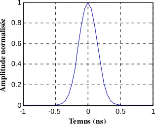
The classic UWB system is generally based on the Gaussian or Monocycle pulses. The mathematical Equa- tion describing Gaussian and monocycle waveform is given in the Equations (1) and (2) successively. These wave-forms are illustrated in Figures 3 and 4.
In order to avoid interference between users, it is nec- essary to encode the data of each user using the pseudo random code such as the PN code [5].
In the study system, the PN code spreads the commu- nication signal spectrum to Ultra Wideband. The length of the code used here is N = 15 chips. After spreading, the signal is modulated by PPM modulation and a classic channel model is considered, i.e. additive white Gaussian
PPM modulation
UWB pulse generator Data
Channel
Block 1 : Transmitter
Correlation Demodulation
Block 2 : Receiver
Recovered Data
PPM modulation
UWB pulse generator Data
Channel
Block 1 : Transmitter
Correlation Demodulation
Block 2 : Receiver
[image:2.595.339.496.591.717.2]Recovered Data
Figure 2. Block diagram of the transmitter-receiver in clas-sic UWB system.
-1 -0.5 0 0.5 1
0 0.2 0.4 0.6 0.8 1
Temps (ns)
A
m
p
lit
u
d
e n
o
rm
a
lis
ée
[image:2.595.75.265.602.728.2]-1 -0.5 0 0.5 1 -1
-0.5 0 0.5 1
Time(ns)
N
o
m
a
lise
d
a
m
p
lit
u
d
[image:3.595.74.257.84.223.2]e
Figure 4. Time presentation of monocycle.
noise (AWGN) with zero mean and two sided spectral density equal to N0/2 [6].
The signal to noise ratio (SNR) is defined, as usual:
10 0
10log Eb
SNR
N
(3)
where b stands for the data bit energy and is the
two-sided noise density power spectrum.
E N0
The transmitted signal is given by the following Equa- tion:
1
2 1 N
i i
S t S m P
(4)S: Symbol to be sent.
m: Pulse waveform.
N: number of transmitted data.
1 for0 otherwise
T t T
P t
The received signal transmitted through the AWGN channel, is given by Equation (5):
*R t S t h t n t
(5) where n is the noise.The receiver is based on a correlation method between the received signal s(t) and the pulse reference corre- sponding to a pulse shape used in the transmitter mono- cycle or Gaussian waveform. The demodulation block is based on the comparison between the position of maxi- mum pulse for each symbol period and the reference time.
In this simulation, a classic simple channel is consid- ered as reference: the Additive Gaussian Noise (AWGN) with zero mean and two-sided spectral density equal to
N0/2. This is justified by the fact that the objective of our
study is to increase the date rate. The possible effects of a real channel will be investigated as an extension of the present study.
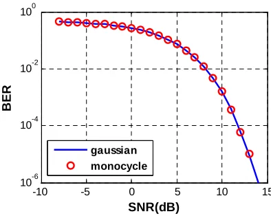
In order to evaluate the performance of the classic system, we calculate the BER values for different SNR in
the monocycle and Gaussian waveforms cases. The result simulations are given in Figure 5. For this purpose, the
BER has been computed using MatlabTM for different
SNR values (105 bits being emitted for each user).
As seen in Figure 4, the Gaussian and the monocycle
waveforms give the same performances in terms of BER values. In fact, in the asynchronous case and in the AWGN, these waveforms have the same performances. In practice, it is more difficult to generate the perfect Gaussian and to have a perfect synchronisation between the transmitter and the receiver.
In order to have high performance in terms of BER, we propose to use other waveforms based on orthogonal functions. In this paper, we compared the performance of the Gegenbauer orthogonal waveforms and the classic pulses.
2.2. Orthogonal Waveform: Gegenbauer Polynomials
The Gegenbauer polynomials are also called ultra- spherical polynomials. These polynomials [5,7,8], de-fined in the interval [−1, +1], satisfy the equation of sec-ond order given in the Equation (6):
2
1 , , 2 2
2 2 0
n n
x G n x xG x
n n G x
(6)
with 1.
The different orders of the Gegenbauer polynomials are bound by the following recurrence equation:
1
, , 2 1 1, ,
2 2
1 2
n
G n x xG n x
n
n G n
n ,
(7)
for n1.
The weight function for these polynomials is given by:
-10 -5 0 5 10 15
10-6 10-4 10-2 100
SNR(dB)
BE
R
gaussian monocycle
[image:3.595.317.514.552.709.2]
2
1/ 2, 1 with 1
w x x 2
0
(8)
To be able to use these polynomials in a UWB com- munication system, the signals generated from them polynomials must be very short. So, the orders of poly- nomials G(n, β, x) are multiplied by a factor corresponding to the square root of the weight function of this polyno-mial family (10). In general we have the following:
,
, ,
, ,
w x G m x G n x
(9)The modified Gegenbauer function is given by the following equation:
, ,
,
*
, , uG n x w x G n x
(10) The first four orders of these functions for beta = 1 are given by the following expressions:
1 4 2
1 4 2
1 4
2 2
1 4
3 2
0, , 1* 1 1, , 2 * 1
2, , 1 4 * 1 3, , 4 8 * 1 u
u
u
u
G x x
G x x x
G x x x
G x x x x
[image:4.595.309.536.537.704.2](11)
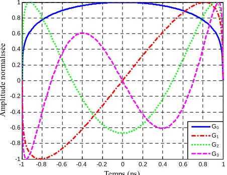
Figure 6 illustrates the time representation of the first
four orders of modified Gegenbauer functions with β = 1. The Gengenbauer polynomial is used in a UWB communication system to construct pulses with narrow widths. In the first studying Gengenbauer waveform is used to modulate data before being compared to the clas- sic waveforms.
In the simulations, we assumed perfect time synchro- nisation between the transmitter and the receiver. How- ever, in the real case, the transmitter and the receiver are not synchronized. So, in order to have synchronization between the transmitter and the receiver, we can use the
-1 -0.8 -0.6 -0.4 -0.2 0 0.2 0.4 0.6 0.8 1 -1
-0.8 -0.6 -0.4 -0.2 0 0.2 0.4 0.6 0.8 1
Temps (ns)
A
m
pl
it
ude nor
m
al
is
ée
[image:4.595.61.287.540.715.2]G0 G1 G2 G3 G0 G1 G2 G3
Figure 6. Modified Gegenbauer functions of four orders.
first correlation to determine the beginning of the com- munication, after the second correlation is used to deter- mine the position of each pulse.
In order to evaluate the performances of this system, we calculate BER for different SNR values with all wave- forms. We compare Gegenbauer waveforms and the clas- sic waveforms in the case of the classic PPM-UWB sys- tem and AWGN channel (Figure 7).
We remark that different waveforms give the same BER result. This similitude is due to the unipolar nature of the waveform. For SNR > 0 dB, different waveforms give the good BER, the value of BER is lower than 10–3.
In fact, in synchronisation case, the effect of the wave- forms is negligible.
In the past, different papers [3] have shown that in the asynchronous case the Gegenbauer waveforms give the higher performance in terms of BER than the classic waveforms. So, in order to take advantage of the modi- fied Gegenbauer functions (low BER) and allow a higher data rate, we propose to associate this system with Bipo- lar PPM modulation, that is, to associating the combina- tion of antipodal and PPM modulations to the preceding system.
3. The Proposed Bipolar PPM System
The proposed system, named Bipolar PPM, will combine PPM and antipodal modulations to increase the data rate.
In order to increase the data rate we increase the data coded with one symbol. We propose exploiting two de- grees of freedom; time shift and amplitude of the sent waveform
To form a symbol, the coder module will group data bits two by two. The most significant bit determines the sign of the impulsion to send, and the least significant bit determines the position of impulsion in the symbol time slot. Equation (12) gives the symbol formula.
-10 -5 0 5 10 15
10-6 10-5 10-4 10-3 10-2 10-1 100
SNR(dB)
BE
R
gauss mono G1 G2 G3 G4 G0
G1
G2
G3
1
2 1 2 1
N
iMSB iLSB
i
S t S m P t S T
(12)where Si is the transmitted symbol, m(t) is the used
waveform and P(t)={1,0}.
In our bipolar PPM system we propose using classic and orthogonal waveforms and comparing them in terms of BER values.
The Table 1 shows an example of the coding tech-
nique (Bipolar PPM) for monocycle waveform.
This novel coding technique will be used to decrease the BER and then to enhance the quality of the commu- nication link. Bipolar PPM modulation will offer a high- speed communication link which is very useful in the case of multimedia transmission. So, we double the data rate and use the orthogonal waveform which will permit to reduce BER and enhance communication quality.
To optimize the data flow, we must optimize the use of the bandwidth. The pulse width depends on the band- width used; in our system we use a pulse of about 1.5 ns wide.
The synchronization is established between the trans- mitter and the receiver. The symbol width must be cho- sen to avoid interferences between pulses, or especially between the pulse Inter-correlation. The safety choice is to avoid the two pulses of adjacent symbols overlapping. The first simulation was done with a symbol width (SW) = 3 pulse width (PW). We used SW as wide as 3 PW to be sure that the pulse inter-correlation does not overlap.
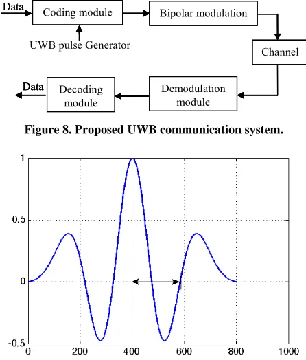
[image:5.595.311.534.247.509.2]In order to get the maximum data rate, we can overlap two symbols to reduce the symbol width. But the overlap must be chosen carefully to maintain good system per-formances. We propose overlapping the two symbols when the maximum of the first autocorrelation occurs. The autocorrelation of the second symbol becomes 0.
Figure 8 presents the autocorrelation of the 2nd order of
Gegenbauer polynomial.
[image:5.595.310.528.545.718.2]As we can see, the autocorrelation has a zero value. When we overlap the two pulses the results is given in
Figure 9. At the decisive moment, the maximum values
remain unchanged and we will maintain the same per- formances as a traditional solution. The data flow given is about 130% faster.
In order to evaluate the performance of the two ver- sions, many simulations have been done with different
Table 1. Principle of the proposed coding technique.
LSB
MSB 0 1
S = + S = +
0
T
T
S = – S = –
1
T
T
waveform. The receiver is based on a correlation method.
Figure 10 presents an example of data encoded by the
proposed technique and the correlation results between the received signal and the pulse reference.
The detection unit computes the maximum and the minimum of the entire symbol period, the position of the maximum and minimum to consider for decision. In our case, we have 4 possibilities (Table 1).
4. BER Simulations Results
The performance of the two systems above has been evaluated in the presence of additive white Gaussian
Coding module Bipolar modulation
Channel
Demodulation module Decoding
module UWB pulse Generator
Data
Data Coding module Bipolar modulation
Channel
Demodulation module Decoding
module UWB pulse Generator
Data
Coding module Bipolar modulation
Channel
Demodulation module Decoding
module UWB pulse Generator
Data Data
Figure 8. Proposed UWB communication system.
Figure 9. Autocorrelation of the 2nd order Gegenbauer polynomial.
noise. For this purpose, the BER has been computed with Matlab for different SNR values, using the bipolar PPM technique.
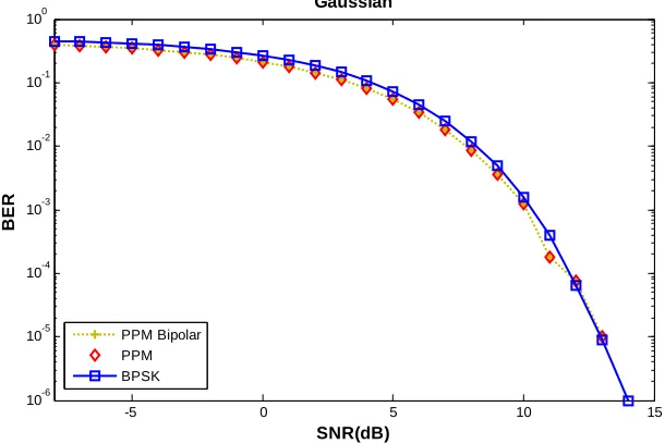
waveforms: Gaussian or monocycle pulses. We deduce that for SNR < 4 dB the PPM and Bipolar PPM modula- tions give the same BER and the antipodal modulation give the higher BER than other modulations. In fact, an- tipodal modulation is more sensitive to noise effect. For SNR > 4 dB the bipolar PPM modulation gives a better performance than the PPM or the antipodal modulation. In Figure 11, we give the BER values for different
Gegenbauer order in the case of 4 users. We deduce that user U1 (associated with MGF order 0) gets better perfor-
mance than the other users. But, the performance is al- most identical for the other orders. S0, the G0, order gives
better performance than the other orders. This difference is due to the unipolar nature of this particular waveform. The G0 can be used to send the priority information. To
guarantee the same performance for different users we will use only four orders G1, G2, G3, and G4.
5. The Theoretical BER Study
In the case of Bipolar PPM modulation, the probability of error is calculated by Equation (2), with d the transmitter data, x the waveform used, b the AWGN and r is the re-ceiver signal, Yk is correlation result between receiver
signal Sk reference signal x. dˆ is the estimated data.
In Figures 11 and 12, we give the BER performance
for three modulation cases when we use the classic
-5 0 5 10 15
10-6 10-5 10-4 10-3 10-2 10-1 100
SNR(dB)
BER
PPM Bipolar
[image:6.595.146.451.517.721.2]G0 G1 G2 G3 G4
Figure 11. BER values for different Gegenbauer waveforms and Bipolar PPM modulation.
-5 0 5 10 15
10-6 10-5 10-4 10-3 10-2 10-1 100
SNR(dB)
BER
Gaussian
PPM Bipolar PPM BPSK
When, we decide that the receiver bit is equal to 1, but the bit transmitter is equal to 0, the additional error of the receiver is considered.
When sk d x1 k
1 k k
k
y r x
So
1 k k k
k
y s b x
1 1
l k k k
k k
y d x x b x
k
,
, ly d corr x x corr b x
cor(x, x) is the auto correlation of the reference signal. β is length of the signal.
In the decisive instant, the estimated data can be given by the following
2
1 1
ˆ sgn
l k k
k k
d y
y d x b x
kWe supposed that the noise is Additive Gaussian, so, the error probability can be given in Equation:
| 1 1
Prob 0 | 1 erfc
2 2 var | 1
| 1
1 Prob 0 | 1 erfc
2 2 var | 0
y d
y d
y d
y d
y d
y d
When
* *
s er
er s
s e
P
P Q
P Q SNR
SNR SNR T F
The probability of error is obtained by the following equation:
* *
er e
P Q SNR T F
with ΔF the frequency band, T the symbol duration, SNRe
the SNR in the input of correlator and SNRs the SNR in
the output of the correlator.
In Figure 13, the theoretical and simulation results are
given for proposed system in case of Bipolar PPM mo- dulation. We deduce that BER values are almost similar in simulation and theoretical case.
Jitter Effect
In this part, in the first time, we fix jitter to 3% of sym-
bol period and study the effect for different modulation techniques and in the second time, we study variable jitter effects in the case of two users. Three modulation techniques, PPM, antipodal and Bipolar PPM modula- tions, are compared for different jitter values. The syn- chronization errors result in a temporal shift between the users. So, we suppose that the users do not send at the same time.
As seen in Figure 14, for SNR < –5 dB the BER is the
same in three modulation cases, PPM, antipodal and Bi- polar PPM. For SNR > –5 dB, the antipodal modulation is less sensitive than other modulations (Bipolar PPM and PPM). In fact antipodal modulation in not based on temporal estimation.
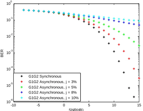
To generate UWB signal, we chose the G1 and G2
waveforms in the case of two users. As you see in Figure 15, we compared the synchronous and asynchronous cases
in Gegenbauer and Bipolar PPM modulation system. We
-10 -5 0 5 10 15
10-10 10-8 10-6 10-4 10-2 100
SNR(dB)
BER
[image:7.595.66.235.137.261.2]simulation theoric
Figure 13. Theoretical and simulation values of BER vs SNR.
-10 -5 0 5 10 15
10-6 10-5 10-4 10-3 10-2 10-1 100
SNR (dB)
BER
PPM jit=3% BPSK jit=3% PPM Bipolar jit=3%
[image:7.595.313.535.314.485.2] [image:7.595.67.272.393.546.2] [image:7.595.312.535.527.705.2]can show that for SNR < 0 dB the performance BER is the same for different jitter values. In this case, the noise effect is more important than the jitter effect. For SNR > 0 dB the noise effect is very lower than the jitter effect. We can deduce that the jitter effect between 3% and 8% the BER values is acceptable. For the jitter effect lower than 10% the proposed receiver is not adapted and it is necessary to modify the processing unit to more adapted receiver. We propose to add known sequence to enhance the synchronisation process.
6. Conclusion
In this study, a proposed UWB communication system is based on the Gegenbauer orthogonal waveforms and the Bipolar PPM modulation. The BER performance of this system is compared to other communication systems based on the classic waveforms (Gaussian and monocy- cle pulses) and other modulations (PPM and antipodal
-10 -5 0 5 10 15
10-6 10-5 10-4 10-3 10-2 10-1 100
SNR(dB)
BE
R
[image:8.595.59.288.321.499.2]G1G2 Synchronous G1G2 Asynchronous, j = 3% G1G2 Asynchronous, j = 5% G1G2 Asynchronous, j = 8% G1G2 Asynchronous, j = 10%
Figure 15. BER vs SNR values for Gegenbauer waveforms and Bipolar PPM modulation with different values for jitter
synchronous and asynchronous cases). (
modulation). In two user cases, our system is evaluated in terms of jitter and SNR values. We can conclude that the performance of the proposed system is good with jitter effect lower than 10%. The simulations and theo- retical results are compared and we remark that we have the same performance. In the future work, the tests will be realised in real propagation environments.
REFERENCES
[1] M.-G. Benedetto and B. R. Vojcic, “Ultra WideBand (UWB) Wireless Communications: A Tutorial,” Journal
of Communication and Networks, Special Issue on Ul-
tra-Wideband Communications, Vol. 5, No. 4, 2003, pp.
290-302.
[2] A. El Abed, F. Boukour, Y. Elhillali and A. Rivenq, “V2V Communication System Using Orthogonal Func- tions and Bipolar PPM Coding,” Proceedings of ITST
Conference, Lille, 20-22 October 2009.
[3] F. Elbahhar, A. Rivenq, J. M. Rouvaen, M. Heddebaut and T. Boukour, “Comparison between DS-CDMA and Modified Gegenbauer Functions MGF for a Multi-User Communication Ultra Wide Band System,” IEE Pro-
ceedings Communications, 22 April 2005.
[4] F. Elbahhar, “Multi-User Ultra Wide Band Communica-tion System Based on Modified Gegenbauer and Hermite Functions,” PhD. Thesis, University of Valenciennes, Valenciennes, 2004.
[5] J. G. Proakis, “Digital Communications,” Mc-Graw Hill, New York, 2001.
[6] R. E. Ziemer and R. L. Peterson, “Introduction to Digital Communication,” Macmillan, New York, 1992.
[7] F. M. Gardner and J. D. Baker, “Simulation Techniques, Models of Communication Signals and Processes,” Wiley, New York, 1997.
[8] F. Elbahhar, A. Rivenq-Menhaj and J. M. Rouvaen, “Multi-User Ultra Wide Band Communication System Based on Modified Gegenbauer and Hermite Functions,”
Wireless Personal Communications, Vol. 34, 2005, pp.