RS232 by USB or SD card communication has increased the speed from 115.2 Kbps to 12 Mbps. In this study DSP processor by Texas Instruments TMS320F2837xd is used which is dual core processor with features of flash programming. This study focuses on understanding and analysing file conversion program to optimize the feed rates and reducing overall machining time of CNC machine. The input to the file conversion program is tool path file generated from CAM software and output is the file with suitable feed rates and other parameters required by CNC machine.
Key Words: CNC, CAM, DSP, USB, SD card.
1. INTRODUCTION
CNC stands for Computer Numerical Control machine, when computers are used to control a Numerical Control (NC) machine tool than the machine is called CNC machine. In other words the use of computers to control the machine tools like lathe, mills, shaper etc is called CNC machine. The cutting operations performed by the CNC is called CNC machining, in CNC machining, programs are designed or prepared first and then it is fed to the CNC machine. According to the program, CNC controls the motion and speed of the machine tools. The main parts of CNC machine are:
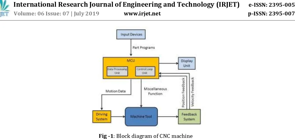
1. Input Devices: These are the devices which are used to input the part program in the CNC machine. There are three commonly used input devices and these are punch tape reader, magnetic tape reader, computer via RS-232-C communication and DSP processors through SD Card or USB communication.
2. Machine Control Unit (MCU): It is the heart of the CNC machine. It performs all the controlling action of the CNC machine, the various functions performed by the MCU are It reads the coded instructions fed into it, decodes the coded instructions, implements interpolation such as linear, circular and helical to generate axis motion commands, feeds the axis motion commands to the amplifier circuits for driving the axis mechanisms, receives the feedback signals of position and speed for each axis drive and implements the auxiliary control functions such as coolant or spindle on/off and tool change.
3. Machine Tool: A CNC machine tool always has a slide table and a spindle to control of the position and speed. The machine table is controlled in X and Y axis directions and the spindle is controlled in the Z axis direction.
4. Driving System: The driving system of a CNC machine consists of amplifier circuits, drive motors and ball lead screw. The MCU feeds the signals like position and speed of each axis to the amplifier circuits. The control signals are than augmented (increased) to actuate the drive motors and then this actuated drive motors rotate the ball lead screw to position the machine table.
5. Feedback System: This system consists of transducers that acts like sensors. It is also known as measuring system; this system contains position and speed transducers that continuously monitor the position and speed of the cutting tool located at any instant. The MCU receives the signals from these transducers and it uses the difference between the reference signals and feedback signals to generate the control signals for correcting the position and speed errors. 6. Display Unit: A monitor is used to display the programs, commands and other useful data of CNC machine.
Fig -1: Block diagram of CNC machine
The user of CNC machine give commands to CNC machine for its operation and this commands are in the form of tool path file, this file is generated using CAD/CAM software. This tool path file contains information regarding the distances of points from X-Y axis, feed, plunge acceleration time, etc. But we cannot give this file as it is to CNC machine because the parameters given by user are not always suitable to CNC machine. If that tool path file is given as it is then it may harm cutting tool, crate vibrations or degrade life of CNC machine. So this file goes from various file conversion processes and finally we get file suitable for CNC machine. So main objective of this project is to understand the flow of file conversion utility, optimize feed rate and minimize machining time in tool path file.
Initially, the CNC technology was applied on basic metal cutting machines such as lathe, milling machines, etc. Then, to increase flexibility of the machines in handling a variety of components and to finish them in a single setup on the same machine, CNC concept was applied to develop a CNC machining centre for machining prismatic components combining operations like milling, drilling, boring and tapping. It does so by taking computer-generated code and converting it with software into electrical signals. The signals control the CNC motors and direct them to move in small increments that are highly precise and repetitive [7]. To get a CNC machine work properly, there needs a dictated software control to get the desired results from a computer design. Traditional CNC machines programmed using CAM software, [3] this CAM (computer aided manufacturing) program is the most difficult part. Note that the CAM doesn't actually run the machine, though it creates the code for machine to follow. In addition, some machines have their own programming language and specific CAM is required to create NC code for the machine to understand. In these cases it can require a post processor that serves to bridge the gap in communication [4]. The post processor usually makes it possible to use any machine and translate anything to the needed code for specific machine and part.
There are many smaller model maker-hobbyist style desktop CNC machines [2]. In general these are lighter in weight, less rigid, less precise, slower and less expensive than their industrial counterparts, but can do well for machining objects for softer materials like plastics, foam, and wax. Some desktop CNC machines may run a lot like a printer. Others have their own closed command system and even dedicated CAM software. A few machines will also accept standard G-code as input; some industrial standard desktop machines do exist with dedicated controllers for doing precise and small work.
2. SYSTEM OVERVIEW
[image:2.595.48.553.48.287.2]Fig -2: Format of Tool path file
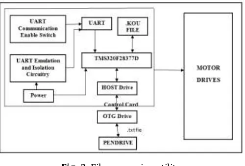
Communication in CNC machine takes place as shown in fig.3 the dual core DSP processor TMS320F28377D is used for fast processing. This processor has the USB 2.0 port and SD card slot so that the file to the machine can be given by the USB. The code for the file conversion converts the file from USB into the .kou file and save it into the pen-drive.
Fig -3: File conversion utility
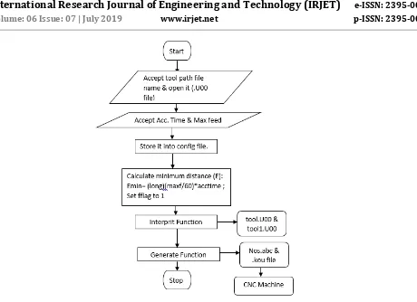
[image:3.595.174.429.184.351.2] [image:3.595.174.424.400.570.2]Fig -4: General flow of file conversion in CNC machine. Steps to generate tool path file:
1. Read the .txt file from pen drive which is called as tool path file.
2. Convert .txt file into the tool.U00 file by doing some calculations of axis parameters.
3. Convert the tool.U00 file into tool1.U00 file by again doing the calculations of maximum feed and minimum linear distance (Emin) for tool processing.
4. Generate the nos.abc file which will indicate the line numbers Generate the .kou file by with suitable feed and distance values
Initially file conversion program checks if tool path file is present or not. If it is present then write parameters like acceleration time, feed and plunge into config file which is created by file conversion code. And if input tool path file is not present then first accept it from user and ask for parameters like acceleration time, feed, and plunge. Finally write this parameters into config file and calculate minimum distance Emin by formula given as,
Emin = [ (long) (Maxf / 60) ] * Acctime
Here, Maxf is maximum allowable feed.
Acctime is acceleration time.
[image:4.595.83.543.50.384.2]Fig -5: File conversion program accepting tool path and other cutting parameters.
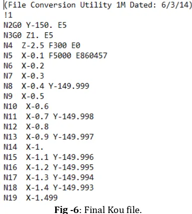
Fig -6: Final Kou file.
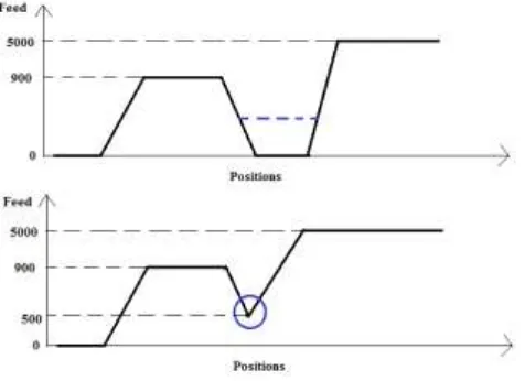
Aim of this project is to minimize or optimize feed rate, also minimize time requirement of cutting tool. In CNC machine specifically milling machine when we start the machine speed of cutting tool is zero and it increases gradually to the speed specified by user. But if there is change in direction or change in axis then cutting tool goes to zero speed from its attained speed and then again from zero it goes to new speed. But this change in direction, axis happens multiple times while doing any job, and hence time wastage happens is very high. Thus time required to complete a work is also high. If we observe properly it seems that there is time wastage when cutting tool tries to attain new speed from 900 to 500 which is shown in fig. 7.
As per below graph when cutting tool wants to attain feed of 5000, first from 900 feed it comes to zero feed and again from zero feed it attains 5000 feed. This feed change is represented in program as condition 6 which occurs when current and previous line feed is different. So as shown in first graph there is time wastage while attaining new feed shown by dotted line. So to avoid this rather than stopping cutting tool to zero speed if we stop it at some intermediate speed i.e. feed 500 shown by circle and then attains the new speed(5000) then some machining time will surely save and when we calculate overall work completion time then it will be very high. This is what exactly done in this project means firstly we have found out points where
[image:5.595.176.425.215.331.2] [image:5.595.199.392.368.583.2]current feed is different than previous feed. And to avoid this conditions calculate Emin using equation no. (1) And subtracted that Emin value from total value and finally we get total value of that line where we need to reinitialize the feed.
[image:6.595.183.421.138.311.2]Fig -7: Reduction of machining time.
Fig.8 shows at line no.135 there is condition 6 occurs due to feed change from 5000 to 900, so at this line we have calculated Emin value by using eq.(1) and total value i.e. 4304 where we can stop decreasing feed at some intermediate point. This total value is compared with previous lines and the point where it matched we have given indication of increasing the feed again to the value we want to achieve i.e. #1 F900.
Fig -8: Feed re-initialization.
CONCLUSIONS
[image:6.595.174.421.410.575.2][7] https://wiki.mcneel.com/rhino/cncbasics.
[8] https://pdfs.semanticscholar.org/b99e/cb86fcdce222c0182de991892482c2a19471.pdf
[9] Jin-Shiang Chang and Syh-Shiuh Yeh, Member, IAENG, “Development of an Interpolation Method for the Acceleration/Deceleration Period Spanning Over Multiple Numerical Control Blocks in CNC Machine Tools”,Vol II IMECS 2018, March 14-16, Hong Kong, 2018.