Experimental study on the nucleate boiling heat transfer
characteristics of a water-based multi-walled carbon
nanotubes nanofluid in a confined space
XIA, Guodong, DU, Mo, CHENG, Lixin and WANG, Wei
Available from Sheffield Hallam University Research Archive (SHURA) at: http://shura.shu.ac.uk/15875/
This document is the author deposited version. You are advised to consult the publisher's version if you wish to cite from it.
Published version
XIA, Guodong, DU, Mo, CHENG, Lixin and WANG, Wei (2017). Experimental study on the nucleate boiling heat transfer characteristics of a water-based multi-walled carbon nanotubes nanofluid in a confined space. International Journal of Heat and Mass Transfer, 113, 59-69.
Copyright and re-use policy
See http://shura.shu.ac.uk/information.html
Experimental study on the nucleate boiling heat transfer characteristics of a
1
water-based multi-walled carbon
nanotubes nanofluid in a confined space
2
Guodong Xiaa,*, Mo Dua, Lixin Chenga,b, Wei Wanga
3
4 a
Key Laboratory of Enhanced Heat Transfer and Energy Conservation, Ministry of Education, 5
College of Environmental and Energy Engineering, Beijing University of Technology, Beijing 6
100124, China 7
b
Department of Engineering and Mathematics, Faculty of Arts, Computing, Engineering and 8
Science, Sheffield Hallam University, City Campus, Howard Street, Sheffield, S1 1WB, UK 9
10
Abstract: Experimental investigation of nucleate boiling heat transfer of a water-based
11
multi-walled carbon nanotubes (MWCNTs) nanofluid in a confined space is presented in this
12
study. First, the effects of four different surfactants on the stability of the nanofluids were
13
investigated and the suitable surfactant gum acacia (GA) was selected for the boiling
14
experiments. Then, the boiling experiments of the nanofluids with various volume fractions
15
(0.005% - 0.2%) of the MWCNTs were conducted at a sub-atmospheric pressure of 1×10⁻³ Pa
16
and the test heat fluxes are from 100 to 740 kW/m2. Furthermore, GA with four different mass
17
fractions was respectively dissolved in the nanofluids to investigate the effect of the GA
18
concentration on the boiling heat transfer. The effects of the heat flux, the concentrations of the
19
MWCNTs and surfactants, the bubble behaviors and the surface conditions after the boiling
20
processes have been analyzed. The results show that the MWCNTs nanofluid can enhance
21
boiling heat transfer as compared to the base fluid. This is mainly caused by the nanoparticles
22
deposition on the boiling surface result in increasing the surface roughness and reducing surface
23
contact angle. It is also found that addition of GA can inhibit the deposition of the nanoparticles
24
but may reduce the boiling heat transfer coefficient of the nanofluids. According to the
experimental results, the maximum heat transfer coefficient enhancement ratio can reach 40.53%.
26
It is also noticed that the heat transfer enhancement ratio decreases with increasing the heat flux
27
at lower heat fluxes from 100 to 340 kW/m2 while it increases with increasing the heat flux at
28
higher fluxes from 340 to 740 kW/m2. At the lower heat fluxes, the deposition layer increases the
29
frequency of bubble formation and thus the boiling heat transfer is strengthened. While at the
30
high heat fluxes, the increasing heat flux may strengthen the capability of the nanoparticles
31
deposition and the disturbance of the nanoparticles and increase the enhancement ratio of heat
32
transfer coefficient.
33
Keywords: nanofluids, MWCNTs, nucleate boiling, heat transfer, enhancement, mechanism
34
35
1. Introduction
36
As a new type of heat transfer medium, nanofluids have been attracting tremendous
37
attention in the field of thermal science and engineering in recent years due to their high thermal
38
conductivity, unique colloidal property and heat transfer behaviors [1-8]. Numerous researchers
39
have conducted investigation into the heat transfer enhancement including single phase and
40
phase change heat transfer using nanofluids [9-20]. In particular, the nucleate boiling heat
41
transfer characteristics in confined spaces are of great interest to removing high heat flux in the
42
microelectronic system, laser devices, green and highly efficient lighting with limited cooling
43
spaces. Although a large number of researchers have investigated on the pool boiling heat
44
transfer characteristics with plenty kinds of nanofluids in unconfined spaces, there lacks study of
45
the characteristics of nucleate boiling heat transfer using the multi-walled carbon nanotubes
46
(MWCNTs) nanofluid in confined spaces at sub-atmospheric pressures. Therefore, it is essential
47
to conduct experimental investigation on the relevant topic.
48
Nanofluids which possess application prospects in the heat transfer field were firstly
proposed by Choi [1] in 1995. From then on, numerous studies of heat transfer of nanofluids
50
have been conducted to understand and explore their fundamentals and applications. The
51
suspension stability and thermal conduction mechanism of nanofluids were studied by Xuan et al.
52
[2], Assael [3] and many other researchers [4, 5]. Hwang et al. [6] prepared four kinds of
53
nanofluids using MWCNTs, CuO and SiO2 nanoparticles. They found that the thermal
54
conductivity of nanofluids was higher than its base fluid and the thermal conductivity of
55
MWCNTs nanofluid was the highest than other nanofluids under the same concentration.
56
As a new research frontier, nanofluids two phase flow and thermal physics is the subject of
57
growing concern [7, 8]. Investigation into the nanofluids phase change phenomena and
58
complicated heat transfer mechanisms have intensively been performed over the past decade.
59
Most researchers have found that the mechanisms of pool boiling heat transfer of nanofluids are
60
different from those of conductive and convective heat transfer of nanofluids [11-13]. Yang and
61
Maa [14] are possibly the first to conduct pool boiling experiments using nanofluids. Their
62
experimental results have indicated that low concentrations of Al2O3 nanofluids with 50 nm
63
diameter can enhance the nucleate pool boiling heat transfer. Xue et al. [15] studied the boiling
64
curve, bubble pattern and contact angle of gum acacia (GA) solution and carbon nanotubes
65
nanofluids. The results showed GA solution enhanced transition boiling heat transfer rate, since
66
GA powder improved the wettability of water. In addition, the critical heat flux of nanofluids
67
pronouncedly increases than that of GA solution due to the deposition of nanoparticles. Amiri et
68
al. [16] performed some pool boiling experiments using carbon nanotubes nanofluid considering
69
different functional groups of nanotubes. They investigated the pool boiling HTC of covalent
70
nanofluids increases than that of deionized water, the heat transfer of non-covalent nanofluids
71
became worse for the reason of the effect of heat resistance. Sarafraz et al. [17-19] study the pool
72
boiling of the MWCNTs and Al2O3 nanofluids on several surfaces and conditions. About
73
MWCNTs nanofluids, they found that the nucleate boiling of the nanofluids could still lead to
the particle deposition, but the micro-finned surfaces broke the deposition to enhance the
75
nucleation site and thus the boiling heat transfer increasing. Shoghl et al. [20] studied the pool
76
boiling heat transfer of nanofluids with ZnO, α-Al2O3 and MWCNTs. Their results indicate that
77
the effects of boiling surface and properties of nanofluids to prove both of them may
78
significantly influence the boiling heat transfer characteristics. For instance, the carbon
79
nanotube-water nanofluids which improved the property of fluids and boiling surface
80
characteristics could enhance the nucleate boiling heat transfer. Quite different results of nucleate
81
boiling heat transfer with various surface conditions have been reported by researchers.
82
Therefore, it is essential to explore and understand the various mechanisms governing the heat
83
transfer processes.
84
According to the foregoing literature review, it is obvious that quite different results of
85
boiling heat transfer with nanofluids and experimental conditions have been obtained. As pointed
86
out by Cheng and Liu [7], there are still challenges to understand the boiling phenomena of
87
nanofluids and their heat transfer mechanisms. Great effort should be made to achieve the
88
complete and systematic knowledge in this aspect. In particular, it’s still necessary to investigate
89
and understand the heat transfer mechanisms through well designed and careful performed
90
experiments and theoretical analysis.
91
Furthermore, the confined heat sink can be traced back to the ribbed radiator of CPU etc. In
92
order to reduce the space and improve the heat efficiency of heat exchanger, flat plate heat pipe
93
thermal spreader replaces the traditional radiator. The boiling in confined space condition just
94
happens in this kind of heat pipe. Rops et al. [21] analyzed the nucleate boiling heat transfer on a
95
spatially confined surface. They found that the depth of the boiling pot, the material of the
96
bounding wall and the diameter of the inlet water supply didn’t affect the enhancement of boiling
97
heat transfer. Zhang et al. [22] reported an experimental investigation of phase-change
98
phenomena in a small confined space. In the study, the boiling and condensation possessed
dramatically impacted each other and the bubbles were limited not only by the distance between
100
boiling and condensation surface, but also by the condensation process. Liu and Yang [23]
101
observed that the boiling heat transfer characteristics were affected by lots of factor in confined
102
space, especially vapor blowing, liquid suction and vapor waving resistance. They also found the
103
enhancement ratio of heat transfer coefficient reduced by the condition of decreasing boiling
104
space or increasing heat flux. However, the study of boiling heat transfer using nanofluids in
105
confined spaces at sub-atmospheric pressures is very limited in the literature so far. Using
106
nanofluid as working fluid seems a promising method of improving the heat transfer
107
performance. The study on the mechanism of boiling heat transfer in confined with nanofluids is
108
helpful to the application of nanofluids. Therefore, it is necessary to conduct the relevant study in
109
this aspect.
110
The objectives of this paper are to experimentally investigate the complicated nucleate
111
boiling mechanisms of nanofluids in a confined space under a sub-atmospheric pressure
112
condition. First, the technology used for preparation of nanofluids is described. Then,
113
experiments of nucleate boiling heat transfer of the MWCNTs nanofluids were conducted in a
114
confined space at a pressure of 1×10⁻³ Pa. The influences of heat flux, the concentration of
115
nanofluids and surfactant on the heat transfer behaviors were presented. The scanning electron
116
microscopy (SEM) photographs of boiling surfaces were used to analyze the modification by the
117
deposition of nanoparticles. The roughness and contact angle of boiling surface and the
118
visualization of the bubble behaviors were used to explain the boiling heat transfer mechanisms
119
of the MWCNTs nanofluids.
120
2. Technology of the water-based MWCNTs nanofluid preparation
121
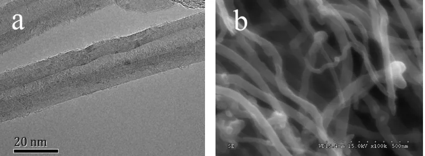
2.1. Characterization of the MWCNTs 122
The multi-walled carbon nanotube nanoparticles were manufactured by Beijing DK Nano
technology Co. Ltd utilizing the chemical vapor deposition method. The physical parameters of
124
the MWCNTs are shown in Table 1. The MWCNTs have an outer diameter of 10-20 nm and an
125
inner diameter of 5-10 nm. Their length is from 10 to 30 µm. The density of the MWCNTs is 2.1
126
g/cm3 and its specific surface area is 200 m2/g. The purity of the MWCNTs is larger than 98%.
127
Figure 1(a) shows a transmission electron microscopy (TEM) photograph of the multiple carbon
128
walls of a tubular structure of the MWCNTs at a scale of 20 nm. Figure 1(b) shows a SEM
129
photograph of the MWCNTs at scale of 500 nm. It can be seen that the nanoparticles
130
agglomerate and twine together. Therefore, it is necessary to scatter the nanoparticles using
131
physical and chemical methods [24-26] at first when preparing the water-based MWCNTs
132
nanofluids.
133
2.2. Technology for preparation of the water-based MWCNTs nanofluid 134
In this study, magnetic stirrer and ultrasonic oscillation were adopted to disperse the
135
MWCNTs in the base fluid deionized water. In addition, some surfactants were added in the base
136
fluid to prevent the second aggregation and suspend the MWCNTs stably for a long time. In
137
general, one step method or two step method is used for the preparation of the nanofluids [27].
138
The two steps method was adopted to prepare the water-based MWCNTs nanofluids. The first
139
step is to prepare the nanoparticles which have been manufactured. The surfactant is added into
140
the base fluid and the solution is well mixed by stirring the solution with a magnetic stirrer for 5
141
minutes. Then the nanoparticles are added into the surfactant solution. After 5 minutes stirring
142
with the magnetic stirrer, the nanofluid is then well mixed with an ultrasonic oscillation for 1
143
hour.
144
Selection of a surfactant was performed at first. Four different popular surfactants which
145
have been used in the nanofluids preparation including cetyltrimethyl ammonium bromide
146
(CTAB), polyvinyl pyrrolidone (PVP), sodium dodecyl benzene sulfonate (SDBS) and gum
147
acacia (GA) were initially used in preparing the MWCNTs nanofluids. The surfactants were all
white particles and manufactured by Tianjin Fuchen Chemical Reagents Factory. The effects of
149
surfactant on the stability of the nanofluids stability were studied through the static precipitation
150
method. All the fresh prepared nanofluid samples with 0.1% volume concentrations of MWCNTs
151
and four kinds of surfactants with 0.1% mass concentration looked similar in appearance, as
152
shown in Fig. 2 (a). As is shown, the nanofluid with CTAB has foam at the liquid surface and the
153
foam remains there for a long time. Foaming was found in the nanofluids with SDBS when
154
prepared it, but it vanished quickly after standing a while. The nonion surfactants (PVP and GA)
155
did not provide any foam. After standing for three months as shown in Fig. 2 (b), some obvious
156
nanoparticles precipitation can be found in the nanofluids with the cation and anion surfactants
157
(CTAB and SDBS). The nanofluids with the nonion surfactants have much better stability than
158
cation and anion surfactants. Yazid et al. [28] pointed out that GA was frequently used as the
159
surfactant to stabilize the carbon nanotubes in water. Our observation has confirmed their
160
statement. Therefore, GA was chosen as the surfactant in preparing the water-based MWCNTs
161
nanofluid used in the boiling experiments.
162
As mentioned above, stable dispersed nanofluids can be prepared adding GA with 0.1%
163
mass concentration. Increasing the concentration of surfactant can explore the influence of the
164
surfactant on boiling, so GA with four different mass concentrations of 0.1%, 0.3%, 0.5% and
165
0.7% was respectively dissolved in the base fluids. The MWCNTs of five different volume
166
fractions of 0.005%, 0.01%, 0.05%, 0.1% and 0.2% were added into the base fluids with or
167
without the surfactant. All the MWCNTs nanofluids with and without GA were prepared for the
168
boiling experiments in the present study.
169
3. Experimental setup and experiment procedure
170
The experimental setup consists of an experimental rig, an assembled test section and a
171
measurement system. The details of these are elaborated here in this section.
3.1 . Experimental rig 173
Figure 3 shows the schematic diagram of the experimental rig used for the nucleate boiling
174
heat transfer experiments in a confined space. The experimental rig mainly includes a
175
thermostatic water container (1), voltage regulator (2), cartridge heaters (3), a copper rod (4),
176
insulation layer (5), a copper sheet (6), quartz window (7), pressure gauge (8), a vacuum pump
177
(9), a high-speed video camera (10), a data acquisition instrument (11) and a PC (12). It consists
178
of a boiling system, a condensation system, a visualization quartz window together with a
179
high-speed video camera, a measurement system and a PC for storing the measured parameters.
180
The boiling system includes a test section, a copper rod, several cartridge heaters and a
181
voltage regulator. Four cartridge heaters were assembled inside a copper rod which is tightly
182
contacted with a flat test section. The cartridge heaters connected to a voltage regulator are used
183
to generate heat through electrical resistance and transfer the heat through the copper rod to the
184
test section to generate boiling processes. The voltage regulator is used to adjust the heat flux in
185
the boiling experiments.
186
The condensation system comprises a condensation chamber, a copper sheet and a
187
thermostatic water container. Water in the thermostatic container was maintained at a constant
188
temperature of 12℃ and used to condensate the vapor generated in the test chamber. The
189
vacuum device is used to remove the gas in the boiling test chamber before fill up the working
190
fluid and maintain a sub-atmospheric pressure condition specified in the boiling experiments.
191
The chamber wall between two copper sheets is made of a quartz window which is used for the
192
visualization of the boiling process using the high-speed video camera.
193
Three T type thermocouples arranged along the axial direction of the copper rod are used to
194
measure the local temperatures along the axis of the round copper rod. With the measured
195
temperatures, the boiling surface temperature of the test section and heat flux can be calculated
196
using one-dimensional linear heat conduction. The surface of the copper sheet was polished with
a 5000# sandpaper before the experiments. The data acquisition system is used to collect the
198
temperatures of three points on the top of the copper heater, the fluid temperature, the vapor
199
temperature in the test chamber and the operation pressure.
200
3.2 . Test section 201
Figure 4 shows the schematic diagram of the test section and the heating system. The
202
heating section is mainly composed of the copper sheet, the copper rod and four cartridge heaters
203
with a diameter of 8 mm. As is showed in Fig. 4, both sections of the upper and lower copper rod
204
are cylindrical and four cartridge heaters are symmetrically arranged at the lower end of the rod
205
to provide heat source for the boiling experiments. The maximum heat flux was adjusted to 750
206
kW/m2 which does not reach critical heat flux as we focused on nucleate boiling heat transfer and
207
mechanisms in our study. The diameter of the upper copper rod is 20 mm, which has the same as
208
the diameter of the boiling surface. Three T type thermocouples are arranged along the axis of
209
the copper rod in the upper section of it to measure the local temperatures and then they are used
210
to calculate the heat flux and the temperature of boiling surface in the boiling experiments.
211
Thermal grease was used to connect the thermocouples and copper rod, so the contact resistance
212
could be neglected. In order to investigate the boiling heat transfer characteristics of the
213
MWCNTs nanofluids at sub-atmospheric pressure, the vacuum system is used to achieve the
214
desired test pressure of 1×10⁻³ Pa. The top surface of the copper rod connected to a horizontal
215
copper sheet which a thickness of only 0.3 mm. The thin sheet of copper has an excellent sealing
216
effect while can neglect horizontal heat conduction effectively because of its thin axial size.
217
3.3 . Experimental procedure 218
To conduct the boiling experiments, first, the vacuum system was run for more than 30
219
minutes to make the test chamber at a sub-atmospheric condition. Second, the working fluid was
220
pumped into the test chamber. Following this, the vacuum device was operated again to
221
discharge the dissolved gas escaped from the working fluid and an operation pressure of 1×10⁻³
Pa was maintained in the test chamber for the boiling experiments. Finally, the condensation
223
system, the circulating water system, the data acquisition system and the power supply was
224
started in sequence. The voltage regulator was used to adjust the voltage at several values of 50 V,
225
70 V, 90 V, 100 V, 110 V, 120 V, and 130 V to generate different heat fluxes used for the test runs
226
in the boiling experiments. After steady state was achieved for each test run, the measured
227
parameters were taken by the data acquisition system and stored in the PC for further data
228
reduction and analysis.
229
4. Data reduction methods and uncertainty analysis
230
4.1. Data reduction methods 231
With the measured parameters of local temperatures in the copper rod and the fluid
232
temperature, the heat flux and boiling heat transfer coefficient may be calculated. The boiling
233
heat transfer coefficient is calculated as:
234 235 w f q h T T
(1) 236
where Tw is the wall surface temperature of the test section and Tf is the saturation temperature
237
of the working fluid, (Tw-Tf) is the superheat degree and q is the heat flux.
238
It’s not accurate to calculated heat flow by the voltage and current of the power supply due
239
to a small amount of heat loss. Therefore, the heat flux would be obtained through steady state
240
heat conduction along the axial direction of the copper rod, assuming one dimensional heat
241
conduction, as
242
3 2 2 1
3 2 2 1
d 1
d 2
T T
T T T
q λ λ
z z z
(2) 243
where λ is the thermal conductivity of the copper heater, dT/dz is the average temperature
244
gradient calculated according to the measured temperatures T1,T2,and T3 as indicatedin Fig. 4, z
is the axial distance between the two temperature measurement points. The calculated value of
246
heat flux is slightly lower than the power supply within 7%.
247
The boiling surface temperature of the test section Tw is determined using one dimensional
248
conduction heat transfer along the vertical direction of the copper heater as:
249
3 2 2 1
w 1 w-1 1
3 2 2 1
d 1
= 0.023
d 2
T T
T T T
T T z T
z z z
(3) 250
To evaluate the enhancement of the nucleate boiling heat transfer of the nanofluids, the heat
251
transfer coefficient enhancement ratio is defined as:
252 nf dw dw 100% h h η h
(4) 253
where hnf and hdw are the boiling heat transfer coefficients of the MWCNTs nanofluids and the
254
deionized water respectively.
255
4.2. Uncertainty analysis 256
The thermocouples were well calibrated before the experiments and the measured
257
temperatures are accurate to ± 0.1 K. The measured pressure gauge is accurate to 0.25% and the
258
distances between the two temperature measurement points are accurate to ± 0.1 mm. The
259
accuracies of voltmeter and ammeter are ± 0.1V and ± 0.025A.
260
Using the methods of Kline and McClintock [29], the uncertainties of heat flux and heat
261
transfer coefficient determined by Eqs. (1) and (2) may be analyzed as follows:
262
2 2 2
q λ δT δz
q λ δT δz
(5)
263
2 2
h δq δT
h q δT
(6)
264
The uncertainly of thermal conductivity could be negligible, because the heater is processed
265
by a piece of standard copper. Table 2 summaries the measurement uncertainties. The uncertainty
of the heat flux is 2.02% and the uncertainty of heat transfer coefficient is 2.78%.
267
5. Experimental result and discussion
268
5.1 . Boiling heat transfer behaviours of the MWCNTs nanofluid and the deionized water 269
In order to compare the boiling heat transfer behaviors of the MWCNTs nanofluids to those
270
of the deionized water, experiments of the test fluids were respectively run from single-phase
271
heat transfer to the nucleate boiling under a sub-atmospheric pressure of 1×10⁻³ Pa.
272
Figure 5(a) shows the instantaneous variation of the boiling surface temperature with the
273
heating time for both the nanofluids with the volume concentration of 0.05% and the base fluid
274
at the heat flux of 740 kW/m2. Figure 5(b) shows the variation of the heat transfer coefficient
275
with the heating time. At the same heat flux, the boiling curve of the MWCNTs nanofluid is
276
similar to that the base fluid. It can be seen that the boiling surface temperatures of both fluids
277
reduce immediately at the boiling incipience. In the meantime, the heat transfer coefficients
278
increase rapidly after the boiling incipience for both fluids. The boiling heat transfer coefficients
279
gradually increase until reaching the steady state of boiling heat transfer. However, there are
280
some differences boiling behaviors between the MWCNTs nanofluid and the base fluid water.
281
On the one hand, the initial boiling surface temperature of the nanofluids is slightly lower than
282
that of water. It indicates that the boiling incipience of the nanofluids occurs earlier than that of
283
water. On the other hand, the boiling surface temperatures of the nanofluids are much lower than
284
those of water and the transient boiling heat transfer coefficients of the nanofluids are much
285
greater than those of water after reaching steady state boiling.
286
Figure 6(a) shows the photo of the MWCNTs deposition on the boiling surface. It shows
287
that the nanoparticles are only adhered on the center of copper sheet although the all test section
288
is uniform smooth copper surface. It can be explained by the following reason: nanofluids are
289
composed of solid phase of the nanoparticles and liquid phase of the deionized water. The phase
change of nanofluids is generated on the boiling surface, and the liquid phase is vaporized and
291
divorced from the surface. However, most of the nanoparticles cannot be taken away by the
292
vapor. Therefore, the soild phase is separated from the liquid phase, so the nanoparticles stay on
293
the boiling surface to form agglomerates and gradually produce a deposition. Thus, more and
294
more nanoparticles are deposited on the boiling surface where the center of the copper sheet is.
295
The result of microscopic photograph by ×80 SEM in Fig. 6(b) shows the rough surface of
296
deposition with pits and bulges. Fig. 6(c) by ×30k SEM proves the point that the deposition is
297
formed by irregular agglomeration of nanotube particles. The surface roughnesses of a copper
298
surface polished by 5000# sandpaper and a nanoparticles surface by 0.05% volume fraction
299
nanofluids deposition were tested using stylus profiler (DektakXT, Bruker, Germany). The
300
copper surface roughness is 20.79 nm and the deposition surface is 4.82 μm. Therefore, the
301
deposition evidently changes the surface roughness of the test section and enhances the boiling
302
heart transfer. This observation agrees to the experimental results by Kole and Dey [30]. They
303
indicated that the surface roughness was influenced by deposition of the nanoparticles.
304
A static contact angle experiment using deionized water on the smooth surface and the
305
deposition surface was measured by contact angle testing system (OCA15EC, Dataphysics,
306
Germany). As is showed in Fig. 7, the nanoparticles deposition surface decrease 16 degree
307
compared with the copper surface. The variation of contact angle has a great influence on the
308
solid-liquid-vapor interface. Das et al. [31] pointed out that functioned surface could reduce the
309
contact angle to enhance boiling heat transfer. The MWCNTs deposition is conductive to wet the
310
surface, make bubbles easier departure from the boiling surface and increase the boiling heat
311
transfer coefficient. Overall, the main reason of enhanced boiling heat transfer is due to the
312
deposition of agglomerate nanoparticles which may increase the nucleate sites and bubble
313
frequency.
5.2 . The effects of the MWCNTs concentrations and the surfactant on the nucleate boiling heat 315
transfer behaviours 316
Experiments of the boiling heat transfer characteristics of the MWCNTs nanofluid with
317
different volume concentrations from 0.005% to 0.2% without surfactant were conducted at a
318
sub-atmospheric pressure of 1×10⁻³ Pa. First, experiments were conducted at a heat flux of 100
319
kW/m2 at which the first bubble would generate for the boiling of the deionized water as
320
observed via visualization. Figure 8(a) shows the variation of heat flux versus the superheat
321
degree for the boiling processes with the MWCNTs nanofluid with three volume concentrations
322
of 0.005%, 0.01% and 0.05% and the deionized water at the steady state test conditions. Figure
323
8(b) shows the variation of boiling heat transfer coefficient versus the heat flux for the
324
corresponding test fluids respectively. The experimental results demonstrate that the nanofluids
325
lead to reducing the boiling surface temperatures compared to those of water under the same heat
326
flux. This means that addition of the MWCNTs in the deionized water can enhance the boiling
327
heat transfer. As shown in Fig. 8(b), the heat flux has a significant effect on the boiling heat
328
transfer coefficient. The boiling heat transfer coefficient increases with increasing the heat flux
329
for both the nanofluids and the base fluid. Furthermore, the boiling heat transfer coefficient of
330
the base fluid can be enhanced by adding the MWCNTs in view of boiling curves shifting to the
331
left. It is obvious as indicated that increasing the concentration of the MWCNTs nanofluid may
332
lead to an enhancement of boiling heat transfer. The enhancement increases with increasing the
333
concentration in the present study. The main reason is that increasing concentration of the
334
nanofluid increases the deposition of the nanoparticles on the boiling heat transfer surface and
335
thus increases the nucleation sites and bubble frequency, as such more bubbles may be generated
336
in the boiling process.
337
Figure 9 shows the comparison of the boiling heat transfer coefficient with the MWCNTs
338
volume concentration at a lower heat flux of 100 kW/m2 and a higher heat flux of 740 kW/m2.
The heat transfer coefficients at the higher heat flux are around 4 times higher than those at the
340
lower heat flux. The heat transfer coefficient is enhanced with increasing the concentration,
341
although the particle deposition may cause some thermal resistance. Therefore, the thickness of
342
deposition would not be the major factor of HTC in this study. It should be noted that there is a
343
fast-increasing of the nucleate boiling heat transfer coefficients occurred at lower concentrations
344
of the nanofluids. However, this variation of the boiling heat transfer coefficients becomes flat at
345
higher concentrations. It means that this is a critical concentration of the nanofluid at which the
346
boiling heat transfer enhancement remains unchanged beyond this critical concentration. This
347
effect of the nanofluids concentration on the boiling heat transfer coefficient enhancement may
348
be attributed to the variation of the surface roughness due to the nanoparticles deposition.
349
However, there is no significant change with further increasing the concentration of the
350
nanofluid beyond the critical concentration and thus the enhancement of the boiling heat transfer
351
coefficient remains unchanged.
352
Addition of a surfactant has an important influence on the physical properties of nanofluid
353
such as the surface tension, viscosity, thermal conductivity [32, 33] and the nucleate boiling heat
354
transfer behaviors [34, 35]. In order to understand the effects of various surfactants on the
355
boiling heat transfer behavior in the present study, four different mass concentrations of GA
356
(0.1%, 0.3%, 0.5%, 0.7%) were added into the nanofluid of 0.1% volume concentration of
357
MWCNTs. Figure 10 shows the variation of the boiling heat transfer coefficient with the mass
358
concentration of GA at three different heat fluxes of 520, 630 and 740 kW/m2. It is obvious that
359
the variations of the heat transfer coefficients clearly indicate that the boiling heat transfer is
360
deteriorated with increasing the concentration of GA in the nanofluids. Furthermore, the heat
361
transfer coefficient curves fall down sharply with increasing the heat flux. It means the negative
362
effect of surfactant GA on the boiling heat transfer becomes more significant at a higher heat flux
363
than those at a lower heat flux.
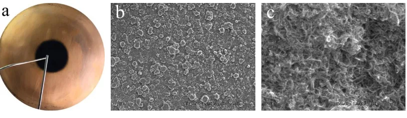
The conditions of the nanofluids before and after the boiling processes were compared with
365
each other as to understand how the boiling process affects the nanofluid. Figure 11 shows the
366
photographs of the MWCNTs nanofluid before and after boiling processes. Figure 11(a) shows
367
the condition of the prepared nanofluids in all concentrations of GA. The nanofluid is black and
368
the multi-walled carbon nanotube particles are well mixed in the base fluid after ultrasonic
369
oscillation. Figure 11 (b) and (c) shows the condition of the MWCNTs nanofluid after boiling
370
without and with surfactant GA, respectively. The MWCNTs in nanofluid without GA
371
agglomerate and deposit at the bottom of nanofluid after boiling while the nanofluid with
372
surfactant GA still keep good dispersion after boiling process. With increasing heat flux, the
373
activity of nanoparticles is more severe in the liquid, which is helpful to the dispersion of
374
nanoparticles by surfactant. However, the main reason for the enhancement of heat transfer by
375
nanofluid is the aggregation layer of the nanoparticles on the boiling surface. According to this
376
observation, it is obvious that the surfactant can make particles uniformly dispersed in the base
377
fluid and inhibit the deposition generated on the boiling surface, reduce the roughness of boiling
378
surface and weaken the active nucleation sites.
379
5.3 . The enhancement ratio of boiling heat transfer coefficients of the MWCNTs nanofluid 380
In order to evaluate the heat transfer enhancement performance, the boiling heat transfer
381
coefficient enhancement ratios of the nanofluids with four different MWCNTs concentrations of
382
0.005%, 0.01%, 0.05% and 0.1% are compared with each other here. Figure 12 shows the
383
variation of the heat transfer coefficient enhancement ratio versus the heat flux from 100 kW/m2
384
to 740 kW/m2. The maximum heat transfer enhancement ratio is 40.53%. Furthermore, the heat
385
transfer enhancement ratio initially decreases with increasing the heat flux until a value of about
386
340 kW/m2 and then increases with increasing the heat flux after this initial decrease. The heat
387
transfer enhancement ratio trends can be explained through the bubble formation and departure
388
behaviors through the visualization of the boiling processes using a high-speed video camera.
In order to observe the variation of bubble formation clearly, boiling experiments of the
390
deionized water were conducted on the surface with deposition. The MWCNTs nanofluid was
391
replaced with the deionized water and the deposition of the MWCNTs was kept on the boiling
392
surface, which was formed by nanofluid with 0.05% concentration after boiling. The bubble
393
generation, growth and departure processes were observed to explain the experimental results
394
and the heat transfer mechanisms.
395
Figure 13 shows the comparison of the bubble generation processes observed at a low heat
396
flux of 100 kW/m2 and a high heat flux of 740 kW/m2 on the boiling surface with the deposition
397
of the MWCNTs. As shown in Fig. 13(a), a bubble emerges on the boiling surface and kept
398
growing. At low pressure, the superheated liquid is full around the bubbles because of the low
399
boiling point of working fluid. On the one hand, with the bubble rising, the bubble volume
400
increases with the increase of the pressure. On the other hand, the bubble dramatically becomes
401
large because the water around the bubble continually vaporizes into the bubble. Shortly
402
afterwards, it departures from the surface slowlywhich may deteriorate the heat transfer from the
403
boiling surface to the fluid. The vapor condenses rapidly after contacting the upper copper
404
surface. At last, the liquid back to initial state without phase-change.
405
As mentioned in the fore-going, the deposition of the nanoparticles on the boiling surface
406
evidently improves the number of nucleation sites and contact angle which can increase and
407
reduce the region of no phase-change. The slower generation and departure of bubble, the more
408
obvious enhancement of heat transfer of deposition. At lower heat flux, the increase of the
409
bubble formation rate is the most important mechanism to enhanced heat transfer by nanofluids.
410
But with increasing the heat flux, the bubble formation rate also increases, hence heat transfer
411
enhancement of nanofluids with increasing heat flux becomes weak. As observed in Fig. 12, this
412
transitional heat flux is around 340 kW/m2 where the bubbles become continuous. Thus the
413
boiling heat transfer coefficient enhancement ratios continue to decline from 100 to 340 kW/m2
heat fluxes.
415
The different boiling patterns at a higher heat flux are shown in Fig. 13(b). It shows that
416
more than one bubble generated from the boiling surface and grew bigger rapidly, and then the
417
bubbles departure becomes fast. New bubbles generated immediately when the previous bubbles
418
just left and the heat transfer becomes stable. Shoghl et al. [20] proposed the effect of both
419
deposition surface and properties of nanofluids influenced the boiling heat transfer coefficient.
420
The enhanced heat transfer mechanisms at high heat fluxes are attributed to not only the increase
421
of the nucleation site density but also the disturbance of particles in fluid. In this study, the
422
experimental results also show that the enhancement ratio of boiling heat transfer coefficient can
423
be increased by improving the effect of deposition and degree of particle disturbance with
424
increasing heat flux at high heat fluxes from 340 to 740 kW/m2.
425
6. Conclusions
426
In the present study, first, stable and uniform nanofluid preparation technology is introduced.
427
Then, experiments of nucleate boiling heat transfer characteristics of the MWCNT water-based
428
nanofluids and the base fluid deionized water in a confined space were conducted at a
429
sub-atmospheric pressure of 1×10⁻³ Pa and heat fluxes from 100 to 740 kW/m2. The uncertainty
430
of the heat flux is 2.02% and the uncertainty of heat transfer coefficient is 2.78%. The roughness
431
and contact angle of the deposited layer and copper surface were compared. The effects of the
432
concentrations of nanoparticles and surfactants on the boiling heat transfer behaviors have been
433
analyzed. The bubble generation and departure characteristics together with the observed particle
434
deposition on the boiling heat transfer surface have been used to explain the experimental results
435
and the heat transfer enhancement mechanisms. The effects of heat flux on the heat transfer
436
enhancement have also been discussed. From the present study, the following conclusions have
437
been reached:
(1) Stable and uniform water-based MWCNTs nanofluid can be produced using the two steps
439
method with addition of GA.
440
(2) Compared with the base fluid, the MWCNTs nanofluid can enhance boiling heat transfer.
441
The maximum heat transfer enhancement can reach 40.53%. The main reason of the heat
442
transfer enhancement is due to the deposition of the MWCNTs on the boiling surface which
443
can increase the roughness and reduce the contact angle.
444
(3) The boiling heat transfer coefficient increases with increasing concentration of the MWCNTs
445
nanofluids owing to increasing nucleation sites of boiling surface and bubble formation rate.
446
A critical volume concentration was found where the boiling heat transfer coefficient will not
447
be further enhanced. In general, it is limited to enhance the boiling heat transfer coefficient
448
by nanofluids because further deposition of the nanoparticles won’t obviously improve the
449
boiling surface.
450
(4) Addition a surfactant may keep the stable and uniform of the MWCNTs nanofluid. However,
451
it seems that the surfactant has a negative effect on the boiling heat transfer in the present
452
study. Addition of GA inhibits the formation of deposition and thus weakens the boiling heat
453
transfer of the nanofluid. The higher the concentration of GA, the worse the boiling heat
454
transfer is.
455
(5) The heat flux has a significant effect on the boiling heat transfer ratio. The boiling heat
456
transfer enhancement ratio decreases with increasing the heat flux when the heat flux is less
457
than 340 W/m2 while it increases with increasing the heat flux beyond this value.
458
(6) The mechanisms of the boiling heat transfer enhancement of the MWCNTs nanofluid are
459
quite different for the lower and higher heat fluxes. At the low heat fluxes, the deposition
460
layer increases the bubble formation frequency, and substantially strengthens the boiling heat
461
transfer. At the high heat fluxes, the increase of nanoparticles concentration and heat flux
462
enhances particle disturbance in fluid. Besides, with the enhancement of deposition and
particle disturbance, the enhancement ratio of boiling heat transfer coefficient is evidently
464
increased.
465
466
Acknowledgements
467
This work is supported by a research fund of the National Natural Science Foundation of China (No.
468
51576005).
469
470
References
[1] S.U.S. Choi, Enhancing thermal conductivity of fluids with nanoparticles, Developments
and Application of Non-newtonian Flows, ASME 66 (1995) 99-105.
[2] Y.M. Xuan, Q. Li, W.F. Hu, Aggregation structure and thermal conductivity of nanofluids,
AIChE J. 49 (4) (2003) 1038-1043.
[3] M.J. Assael, C.F. Chen, I. Metaxa, W.A. Wakeham, Thermal Conductivity of Suspensions
of Carbon Nanotubes in Water, Int. J. Thermophys. 25 (4) (2004) 971-985.
[4] S.A. Angayarkanni, J. Philip, Review on thermal properties of nanofluids: Recent
developments, Adv. Colloid Interface Sci. 225 (2015) 146-176.
[5] M. Raja, R. Vijayan, P. Dineshkumar, M. Venkatesan, Review on nanofluids
characterization, heat transfer characteristics and applications, Renew. Sust. Energ. Rev. 64
(2006) 163-173.
[6] Y.J. Hwang, Y.C. Ahn, H.S. Shin, C.G. Lee, G.T. Kim, H.S. Park, J.K. Lee, Investigation on
characteristics of thermal conductivity enhancement of nanofluids, Curr. Appl. Phys. 6
(2006) 1068-1071.
[7] L. Cheng, L. Liu, Boiling and two-phase flow phenomena of refrigerant-based nanofluids:
[8] L. Cheng, E.P. Bandarra Filho, J.R. Thome, Nanofluid two-phase flow and thermal physics:
A new research frontier of nanotechnology and its challenges, J. Nanosci. Nanotech. 8
(2008) 3315-3332.
[9] G.D. Xia, R. Liu, J. Wang, M. Du, The characteristics of convective heat transfer in
microchannel heat sinks using Al2O3 and TiO2 nanofluids, Int. Commun. Heat Mass Transf.
76 (2016) 256-264.
[10] D. Yadav, J Wang, R Bhargava, J Lee, H.H. Cho, Numerical investigation of the effect of
magnetic field on the onset of nanofluid convection, Appl. Therm. Eng. 103 (2016)
1441-1449.
[11] D. Ciloglu, A. Bolukbasi, A comprehensive review on pool boiling of nanofluids, Appl.
Therm. Eng. 84 (2015) 45-63.
[12] R. Kamatchi, S. Venkatachalapathy, Parametric study of pool boiling heat transfer with
nanofluids fortheenhancement of critical heat flux: A review, Int. J. Therm. Sci. 87 (2015)
228-240.
[13] X.D. Fang, Y.F. Chen, H.L. Zhang, W.W. Chen, A.Q. Dong, R. Wang, Heat transfer and
critical heat flux of nanofluid boiling: A comprehensive review, Renew. Sust. Energ. Rev.
62 (2016) 924-940.
[14] Y.M. Yang, J.R. Maa, Boiling of suspension of solid particles in water, Int. J. Heat Mass
Transf. 27 (1984) 145-147.
[15] H.S. Xue, J.R. Fan, R.H. Hong, Y.C. HU, Characteristic boiling curve of carbon nanotube
nanofluid as determined by the transient calorimeter technique, Appl. Phys. Lett. 90 (90)
(2007) 99-105.
[16] A. Amiri, M. Shanbedi, H. Amiri, S. Zeinali Heris, S.N. Kazi, et al, Pool boiling heat
transfer of CNT/water nanofluids, Appl. Therm. Eng. 71 (71) (2014) 450–459.
Al2O3–ethyleneglycol nanofluids, Int. Commun. Heat Mass Transf. 58 (2014) 96-104.
[18] M.M. Sarafraz, F. Hormozi, Experimental investigation on the pool boiling heat transfer to
aqueous multi-walled carbon nanotube nanofluids on the micro-finned surfaces, Int. J.
Therm. Sci. 100 (22) (2015) 255-266.
[19] M.M. Sarafraz, F. Hormozi, S.M. Peyghambarzadeh, Pool boiling heat transfer to aqueous
alumina nano-fluids on the plain and concentric circular micro-structured (CCM) surfaces,
Exp. Therm. Fluid Sci. 72 (2016) 125-139.
[20] S.N. Shoghl, M. Bahrami, M. Jamialahmadi, The Boiling Performance of ZnO, α-Al2O3
and MWCNTs-Water Nanofluids: An Experimental Study, Exp. Therm. Fluid Sci. 80 (2016)
27-39.
[21] C.M. Rops, R. Lindken, J.F.M. Velthuis, J. Westerweel, Enhanced heat transfer in confined
pool boiling, Int. J. Heat Fluid Flow 30 (4) (2009) 751-760.
[22] G.M. Zhang, Z.L. Liu, C. Wang, An experimental study of boiling and condensation
co-existing phase change heat transfer in small confined space, Int. J. Heat Mass Transf. 64
(2) (2013) 1082-1090.
[23] C.F. Liu, C.Y. Yang, Effect of space distance for boiling heat transfer on micro porous
coated surface in confined space, Exp. Therm. Fluid Sci. 50 (10) (2013) 163-171.
[24] A. Ghozatloo, A.M. Rashidi, M. Shariaty-Niasar, Effects of surface modification on the
dispersion and thermal conductivity of CNT-water nanofluids, Int. Commun. Heat Mass
Transf. 54 (46) (2014) 304-310.
[25] M. Farbod, A. Ahangarpour, S.G. Etemad, Stability and thermal conductivity of
water-based carbon nanotube nanofluids, PARTICUOLOGY 22 (5) (2015) 59-65.
[26] W.S. Sarsam, A. Amiri, S.N. Kazi, A.Badarudin, Stability and thermophysical properties of
non-covalently functionalized graphene nanoplatelets nanofluids, Energy Convers. Manage.
[27] D.K. Devendira, V.A. Amirtham, A review on preparation, characterization, properties and
applications of nanofluids, Renew. Sust. Energ. Rev. 60 (2016) 21-40.
[28] M.N.A.W.M. Yazid, N.A.C. Sidik, R. Mamat, G. Najafi, A review of the impact of
preparation on stability of carbon nanotube nanofluids, Int. Commun. Heat Mass Transf. 78
(2016) 253-263.
[29] S.J. Kline, F.A. McClintock, Describing Uncertainties in Single-Sample Experiments,
Mech. Eng. 75 (1) (1953) 3-8.
[30] M. Kole, T.K. Dey, Investigations on the pool boiling heat transfer and critical heat flux of
ZnO-ethylene glycol nanofluids, Appl. Therm. Eng. 37 (16) (2012) 112-119.
[31] S. Das, B. Saha, S. Bhaumik, Experimental study of nucleate pool boiling heat transfer of
water by surface functionalization with SiO2 nanostructure, Exp. Therm. Fluid Sci. 81
(2016) 454-465.
[32] M.Z. Zhou, G.D. Xia, J. Li, L. Chai, L.J. Zhou, Analysis of factors influencing thermal
conductivity and viscosity in different kinds of surfactant solutions, Exp. Therm. Fluid Sci.
36 (2012) 22-29.
[33] G.D. Xia, H.M. Jiang, R. Liu, Y.L. Zhai, Effects of surfactant on the stability and thermal
conductivity of Al2O3-deionized water nanofluids, Int. J. Therm. Sci. 48 (2014) 118-124.
[34] L. Cheng, D. Mewes, A. Luke, Boiling phenomena with surfactants and polymeric
additives: A state-of-the-art review, Int. J. Heat Mass Transf. 50 (13-14) (2007) 2744-2771.
[35] A. Najim, V. More, A. Thorat, S. Patil, S. Savale, Enhancement of pool boiling heat
transfer using innovative non-ionic surfactant on a wire heater, Exp. Therm. Fluid Sci. 82
Nomenclatures
h heat transfer coefficient, W/ m2∙K
q heat flux, W/m2
T temperature, K
z distance between two temperature measurement points, m
Greek symbols
λ thermal conductivity, W/ m∙K
η enhancement ratio of boiling heat transfer coefficient, %
Subscripts
f working fluid
w boiling surface
nf nanofluids
dw deionized water
Abbreviations
GA gum acacia
MWCNTs multi-walled carbon nanotubes
SEM scanning electron microscopy
List of Table and Figure Captions
Table 1 Parameters of multi-walled carbon nanotube nanoparticles.
Table 2 The summary of measurement uncertainties
Fig. 1. Microscopic photograph of the MWCNTs by (a) TEM and (b) SEM .
Fig. 2. The images of the dispersed MWCNTs nanofluids with four different surfactants: (a)
Fresh prepared nanofluids and (b) Nanofluids after standing for three months.
Fig. 3. Schematic diagram of the experimental rig. (1) Thermostatic water container, (2) Voltage
regulator, (3) Cartridge heater, (4) Copper rod, (5) Insulation layer, (6) Copper sheet, (7) Quartz
window (8) Pressure gauge, (9) Vacuum pump, (10) High-speed camera, (11) Data acquisition
instrument, (12) PC.
Fig. 4. Schematic diagram of the test section and the heating arrangement.
Fig. 5. Boiling curves of the MWCNTs nanofluid with a volume concentration of 0.05% and deionized
water: (a) Boiling surface temperature vs. time; (b) Boiling heat transfer coefficient vs. time.
Fig. 6. Macroscopic and microscopic photographs of nanoparticles deposition: (a) by camera, (b)
by ×80 SEM, (c) by ×30k SEM.
Fig. 7. Static contact angle of (a) a smooth copper surface and (b) a nanoparticles deposition
surface.
Fig. 8. Boiling curves of the MWCNTs nanofluids with three different volume concentrations of
0.005%, 0.01% and 0.05%, and the deionized water: (a) Heat flux vs. superheat degree, (b)
Boiling heat transfer coefficient vs. heat flux.
Fig. 9. Variation of the boiling heat transfer coefficients of the MWCNTs nanofluids with the
concentrations at two different heat fluxes of 100 kW/m2 and 740 kW/m2.
Fig. 10. Variation of the boiling heat transfer coefficient with the mass concentration of surfactant
GA at three different heat fluxes of 520 kW/m2, 630 kW/m2 and 740 kW/m2.
Fig. 11. Agglomeration condition of the MWCNTs nanofluids: (a) before boiling, (b) without GA
after boiling, (c) with GA after boiling.
Fig. 12. Variation of the boiling heat transfer coefficient enhancement ratios of the MWCNTs
nanofluids with the heat flux for four different volume fractions of 0.005%, 0.01%, 0.05% and
Fig. 13. Photographs of the bubble generation, growth and departure on the boiling surface with
[image:27.595.67.546.172.227.2]the MWCNTs deposition at two heat fluxes: (a) 100kW/m2 and (b) 740kW/m2.
Table 1
Parameters of the multi-walled carbon nanotube nanoparticles.
Outer diameter(nm)
Inner diameter(nm)
Length
(μm) Purity
Density (g/cm3)
Specific surface area(m2/g)
Table 2
The summary of measurement uncertainties.
Parameter Unit Uncertainty
Temperature K ± 0.1
Distance between thermal couples mm ± 0.1
Voltage V ± 0.1
Current A ±0.025
Pressure Pa 0.25%
Heat flux W/m2 2.02%
(a) Fresh prepared nanofluids.
(b) Nanofluids after standing for three months.
Fig. 2. The images of the dispersed MWCNTs nanofluids with four different surfactants: (a)
[image:31.595.186.425.70.326.2]Fig. 3. Schematic diagram of the experimental rig.
(1) Thermostatic water container, (2) Voltage regulator, (3) Cartridge heater, (4) Copper rod,
(5) Insulation layer, (6) Copper sheet, (7) Quartz window (8) Pressure gauge, (9) Vacuum
Fig. 5. Boiling curves of the MWCNTs nanofluid with a volume concentration of 0.05% and deionized
Fig. 6. Macroscopic and microscopic photographs of nanoparticles deposition: (a) by camera, (b)
Fig. 7. Static contact angle of (a) a smooth copper surface and (b) a nanoparticles deposition
[image:36.595.107.504.73.209.2]Fig. 8. Boiling curves of the MWCNTs nanofluids with three different volume concentrations of
0.005%, 0.01% and 0.05%, and the deionized water: (a) Heat flux vs. superheat degree, (b)
Fig. 9. Variation of the boiling heat transfer coefficients of the MWCNTs nanofluids with the
[image:38.595.151.459.70.308.2]Fig. 10. Variation of the boiling heat transfer coefficient with the mass concentration of surfactant
Fig. 11. Agglomeration condition of the MWCNTs nanofluids: (a) before boiling, (b) without GA
Fig. 12. Variation of the boiling heat transfer coefficient enhancement ratios of the MWCNTs
nanofluids with the heat flux for four different volume fractions of 0.005%, 0.01%, 0.05% and
[image:41.595.125.484.69.358.2](a)
[image:42.595.84.527.58.442.2](b)
Fig. 13. Photographs of the bubble generation, growth and departure on the boiling surface with