A new aircraft architecture based on the ACHEON Coanda
effect nozzle: flight model and energy evaluation
TRANCOSSI, Michele <http://orcid.org/0000-0002-7286-5228>, MADONIA,
Mauro <http://orcid.org/0000-0001-7094-1437>, DUMAS, Antonio
<http://orcid.org/0000-0001-7111-6113>, ANGELI, Diego
<http://orcid.org/0000-0002-0848-2409>, BINGHAM, Chris
<http://orcid.org/0000-0001-6684-7894>, DAS, Shyam Sumanta
<http://orcid.org/0000-0002-8687-7158>, GRIMACCIA, Francesco
<http://orcid.org/0000-0003-2568-9927>, PASCOA, Jose
<http://orcid.org/0000-0001-7019-3766>, PORRECA, Eliana, SMITH, Tim
<http://orcid.org/0000-0003-2259-069X>, STEWART, Paul, SUBHASH,
Maharshi <http://orcid.org/0000-0002-2217-9334>, SUNOL, Anna and
VUCINIC, Dean <http://orcid.org/0000-0002-1644-4277>
Available from Sheffield Hallam University Research Archive (SHURA) at:
http://shura.shu.ac.uk/11727/
This document is the author deposited version. You are advised to consult the
publisher's version if you wish to cite from it.
Published version
TRANCOSSI, Michele, MADONIA, Mauro, DUMAS, Antonio, ANGELI, Diego,
BINGHAM, Chris, DAS, Shyam Sumanta, GRIMACCIA, Francesco, PASCOA, Jose,
PORRECA, Eliana, SMITH, Tim, STEWART, Paul, SUBHASH, Maharshi, SUNOL,
Anna and VUCINIC, Dean (2016). A new aircraft architecture based on the ACHEON
Coanda effect nozzle: flight model and energy evaluation. European Transport
Research Review, 8 (2), 11 (1)-11 (21).
Copyright and re-use policy
See http://shura.shu.ac.uk/information.html
Sheffield Hallam University Research Archive
ORIGINAL PAPER
A new aircraft architecture based on the ACHEON Coanda effect
nozzle: flight model and energy evaluation
Michele Trancossi1&Mauro Madonia2&Antonio Dumas2&Diego Angeli2& Chris Bingham3&Shyam Sumanta Das4&Francesco Grimaccia5,6& Jose Pascoa Marques4&Eliana Porreca7&Tim Smith3&Paul Stewart8& Maharshi Subhash2&Anna Sunol9&Dean Vucinic9
Received: 6 December 2014 / Accepted: 10 February 2016
#The Author(s) 2016. This article is published with open access at SpringerLink.com
Abstract
Purpose Aeronautic transport has an effective necessity of reducing fuel consumption and emissions to deliver efficiency and competitiveness driven by today commercial and legisla-tive requirements. Actual aircraft configurations scenario al-lows envisaging the signs of a diffused technological maturity and they seem very near their limits. This scenario clearly shows the necessity of radical innovations with particular ref-erence to propulsion systems and to aircraftarchitecture consequently.
Methods This paper presents analyses and discusses a prom-ising propulsive architecture based on an innovative nozzle,
which allows realizing the selective adhesion of two imping-ing streams to two facimping-ing jets to two facimping-ing Coanda surfaces. This propulsion system is known with the acronym ACHEON (Aerial Coanda High Efficiency Orienting Nozzle). This paper investigates how the application of an all-electric ACHEONs propulsion system to a very traditional commuter aircraft can improve its relevant performances. This paper considers the constraints imposed by current state-of-the-art electric motors, drives, storage and conversion systems in terms of both power/energy density and performance and considers two dif-ferent aircraft configurations: one using battery only and one adopting a more sophisticated hybrid cogeneration. The ne-cessity of producing a very solid analysis has forced to limit the deflection of the jet in a very conservative range (±15°) with respect to the horizontal. This range can be surely pro-duced also by not optimal configurations and allow minimiz-ing the use of DBD. From the study of general flight dynamics equations of the aircraft in two-dimensional form it has been possible to determine with a high level of accuracy the advan-tages that ACHEON brings in terms of reduced stall speed and of reduced take-off and landing distances. Additionally, it in-cludes an effective energy analysis focusing on the efficiency and environmental advantages of the electric ACHEON based propulsion by assuming the today industrial grade high capac-ity batteries with a power denscapac-ity of 207 Wh/kg.
Results It has been clearly demonstrated that a short flight could be possible adopting battery energy storage, and longer duration could be possible by adopting a more sophisticated cogeneration system, which is based on cogeneration from a well-known turboprop, which is mostly used in helicopter propulsion. This electric generation system can be empowered by recovering the heat and using it to increase the temperature of the jet. It is possible to transfer this considerable amount of heat to the jet by convection and direct fluid mixing. In this way, it is possible to increase the energy of the jets of an
* Michele Trancossi [email protected]
1
ACES, Sheffield Hallam University, City Campus, Howard Street, Sheffield S1 1WB, UK
2 Università di Modena e Reggio Emilia, Di.S.M.I., Via Amendola, 2,
42100 Reggio Emilia, Italy
3
School of Engineering, Brayford Pool, University of Lincoln, Lincoln LN6 7TS, UK
4 Faculty of Engineering, Convento de Santo António, Universidade
da Beira Interior, 6201-001 Covilhã, Portugal
5 Nimbus srl, Lombardore, Torino, Italy 6
Dipartimento di Energia, Politecnico di Milano, Campus Bovisa - Via La Masa, 34, 20156 Milan, Italy
7 Reggio Emilia Innovazione, via Sicilia 31, 42122 Reggio
Emilia, Italy
8
Institute for Innovation in Sustainable Engineering, University of Derby, Lonsdale House, Quaker Lane, Derby DE1 3HB, UK
9
Department of Mechanical Engineering, Vrije Universiteit Brussel, Triomflaan 43 - Room TL43/2.12, B-1050 Brussels, Belgium
(2016) 8:11
amount that allows more than recover the pressure losses in the straitening section. In this case, it is then possible to dem-onstrate an adequate autonomy of flight and operative range of the aircraft. The proposed architecture, which is within the limits of the most conservative results obtained, demonstrates significant additional benefits for aircraft manoeuvrability. In conclusion, this paper has presented the implantation of ACHEON on well-known traditional aircraft, verifying the suitability and effectiveness of the proposed system both in terms of endurance with a cogeneration architecture and in terms of manoeuvrability. It has demonstrated the potential of the system in terms of both takeoff and landing space requirements.
ConclusionsThis innovation opens interesting perspectives for the future implementation of this new vector and thrust propulsion system, especially in the area of greening the aero-nautic sector. It has also demonstrated that ACHEON has the potential of renovating completely a classic old aircraft con-figuration such as the one of Cessna 402.
Keywords Aerial propulsion . Coanda . Energy efficiency . Energy model . Flight model . Short takeoff and landing
Abbreviations
α Angle of attach (rad, deg)
γ Climb angle (rad, deg)
λ Wing taper ratio (−)
μ Friction coefficient (−) a Acceleration (m/s2)
aL Variation of lift coefficient with angle of attack (−)
Ax,y Planform Area (m2)
Ax,z Frontal section (m
2
) AR Aspect ratio (1/m) b Wing length (m) CD Drag coefficient (−)
CD0 Drag coefficient with lift at null angle of attach (−)
CL Lift coefficient (−)
CL0 Lift coefficient at null angle of attack (−)
cr Wing root chord (m)
ct Wing tip chord (m)
c Average wing chord (m) D Drag force (N)
e Wing planform efficiency factor (−) K Drag increase coefficient with Lift (−) kt Static thrust coefficient (−)
Kuc Factor of flap deflection (−)
L Lift force (N)
m Mass of the airplane (kg) M Mach number (−)
n Speed of rotation of the fan (RPM) P Power of the engine motor (kW) Rin Inlet radius of the ducted fan unit (m)
Rm Radius of the motor (m)
Rout Outlet radius of the ducted fan unit (m)
Rf Fan radius of the ducted fan unit (m)
S Wing planform area (m2) t Angle of thrust (rad) T Thrust (N)
u Aircraft speed (m/s) ustall Aircraft stall speed (m/s)
Vexit Air speed at the outlet of the ducted fan unit
W Weight (kg)
W/S Wing loading (N/m2)
1 Introduction
1.1 Generalities
The future of the aeronautic domain is predicated on the ne-cessity to meet public and legislative demand in terms of in-creased safety and capacity, reduced emissions and noise, higher manoeuvrability and increased flexibility of use, re-duced time for travel and take off, and rere-duced landing space requirements. For example, NASA has launched the
‘Revolutionize Aviation’ program, demonstrating that
‘game-changing’novel propulsion systems are necessary to enable the design of revolutionary aircraft that could meet future and greener needs [1].
The ACHEON (Aerial Coanda High Efficiency Orienting-jet Nozzle) [2] is a new propulsive architecture that aims to fulfil most of these goals. It defines a novel class of aerial vehicles, which are green, all electric, with improved manoeuvrability, reduced takeoff, and landing spaces. Cen et al. [3] have verified that this system has the potential of increasing the manoeuvrability of a high performance jet with a significant increase in performance.
This paper considers a more conservative domain. It aims to verify how ACHEON can be implemented inside the archi-tecture of a traditional twin-engine transport aircraft and ana-lyzes the benefits and the feasibility of the system. A novel class of transport aircraft, which is designed to benefit of ACHEON nozzle, is subsequently defined inside this paper.
1.2 ACHEON nozzle architecture
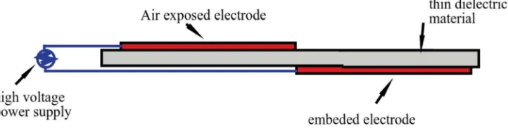
subsequent to investigating the stability problem, the project has integrated the Coanda effect nozzle with a dielectric bar-rier discharge (DBD) to increase the stability of the system, as defined by Cattafesta [9] and improved by Xisto [10].
The architecture of the nozzle as originally defined by the patent is represented in Fig.1.
The ACHEON nozzle (1) is capable of mixing two primi-tive fluid jets (2) and (2') and producing a selecprimi-tive and con-trollable angular deviation of the synthetic jet (7) without any moving mechanical part. The nozzle (1) is also capable of changing the direction of this jet in a continuous and dynamic manner to allow the jet to sweep a preset and arbitrary angle. The nozzle (1) is constituted, in a first part thereof, by a con-duit (8) divided into two channels by a central baffle (9) and, in a second part thereof, by a convergence zone and an out-flow mouth (5) whose walls have a curvilinear profile and are connected seamlessly to the walls of the conduit. Dragan [11] has independently validated the preliminary Coanda effect model by Trancossi and Trancossi and Dumas.
A general overview has been produced by Dumas et al. [12]
1.3 Coanda effect modelling
Significant research activity has been conducted on Coanda effect modelling and analysis. In particular, Trancossi, Dumas et al. [13] produced a theoretical model of Coanda attachment mechanisms and the laws of the Coanda effect. The proposed model has been realized by integration of Navier Stokes equa-tions starting from the Dragan [14] model. The authors con-sider a very conventional setup in order to define by a theo-retical analysis a mathematical model of the Coanda adhesion and define a preliminary model, which could be suitable for simple engineering calculations and preliminary comprehen-sion of the model by elementary equations. A parametric mod-el has defined as a function of the main cinematic and geo-metric parameters. The final model relates to three
fundamental parameters: outlet section, Coanda surfaces radi-us and inlet velocities. Turbulent and laminar models have been defined. Validation through a large CDF development programme has been produced in a regime of stream velocities from 5 to 40 m/s with good correlation results.
This activity has been improved by Subhash and Dumas [15], who have produced a large set of numerical computa-tions with different turbulence models on an air jet flowing tangentially over the curved surface. In particular, they have obtained that without resolution of the viscous sub-layer, since it is not possible to determine the computationally indepen-dent angle of jet deflection and boundary layer thickness. The boundary layer analysis has been performed at different radius of curvatures and at jet Reynolds numbers ranging from ap-proximately about 2400–10,000. The skin-friction coefficient has been also studied at the separation in relation to the surface radius and jet Reynolds number. In this research work, the inter-relation between flow and geometric parameters has been identified for the further design of the Coanda nozzle flow.
Dumas, Subhash at al. [16] have analysed the effect of the temperature of the surface on the Coanda effect adhesion. This activity has led to the identification of a negative effect of heated Coanda surfaces on the adhesion phenomena.
Das at al. [17] have carried out numerical simulations to investigate Coanda flow over a curved surface and analysed the application to the ACHEON system. He has observed the effect of Dielectric barrier discharge (DBD) plasma actuators, concluding that it has an effective capacity both of stabilizing the behaviour of the system and of increasing the angle of adhesion. CFD computations were performed under subsonic condition by Reynolds averaged Navier stokes equations (RANS).
1.4 Coanda nozzle modelling
jet nozzle. The uncertainness levels of the model are discussed and novel aircraft architectures based on it are presented. A CFD validation programme is presented focusing on validat-ing the model and the designs produced. Pascoa et al. [20] have produced an effective bibliographic analysis on thrust deflection systems producing an effective comparison with other thrust and vector system.
1.5 Dielectric barrier discharge
The Dielectric barrier concept and architecture, which are used in the ACHEON nozzle, are derived directly from the one defined by Pascoa et al. [21] in 2009, and is presented in
Fig.2. Abdollahzadeh and Pascoa [22] introduced a generic
analytical approach that can be used to predict analytically the momentum transfer in DBDs, allowing a better analytical analysis of the dynamic behaviour of the ACHEON nozzle.
Abdollahzadeh et al. [23] have explored the use of thermal DBDs. Until the moment, only non-thermal DBDs have been used for ACHEON, due to the lower flow speeds involved. This is a general paper dealing with the numerical modelling of nanosecond pulse micro-shock wave plasma actuators. As verified by Subhash et al. thermal effects are negative at low Reynolds number, but becomes an effective solution at high Mach numbers, including transonic or supersonic conditions.
2 Definition of the problem
2.1 Generalities
Sunol and Vucinic [24] have started a preliminary analysis of integration of the ACHEON nozzle into an aerial Vehicle. Building upon this preliminary result, this paper aims to ana-lyze how the ACHEON nozzle can be further integrated into aircraft architecture, and in particular will focus on the defini-tion of a specific aircraft model taking maximum advantage of this nozzle.
Current S-VTOL aircraft are generally not optimized de-signs because they are based on very traditional aircraft archi-tectures not specifically designed for this kind of operation. The design optimization will focus on a simplified 2D plane of motion considering initially only the advantage during take off, climbing and landing operations.
Four forces act on an aircraft in flight: lift, weight, thrust, and drag. For an aircraft in cruise, the four forces are balanced, and the aircraft moves at a constant velocity and altitude. Any altitude change makes them diverge from equilibrium. Vertical and horizontal axes of the aircraft have their origin in the center of gravity. Two flight paths are designed as red and blue lines inclined to the horizontal at anglecas in Fig.3. Take off and landing operation will be evaluated.
The results obtained allow the definition of a configuration that allows the installation of ACHEON on a very conserva-tive classical airplane design.
This paper will analyze flight mechanics problems starting from a rigorous Newtonian approach, considering basic equa-tions derived from Newton’s second law. to enable analysis and understanding of the benefits of the ACHEON nozzle under different conditions.
Preliminary calculations will be performed assuming the effects of the pitch as included in the Drag and Lift aerody-namic coefficient.
2.2 Final Remarks about methodology
Because of the methodological analysis performed, some the-oretical benefits have clearly been shown. This analysis and FAR regulations enables the production of an effective mis-sion analysis based on a real plane model.
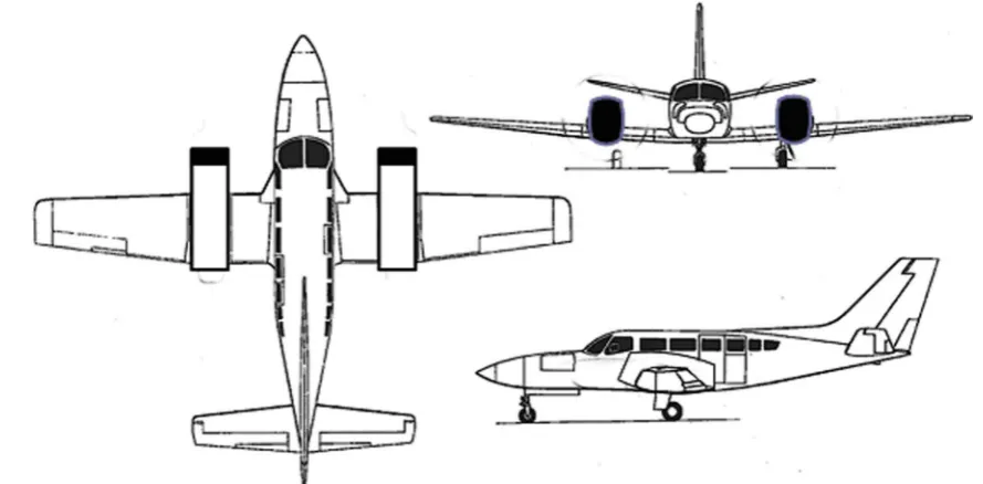
The characteristics of flight related to the considered poten-tial ACHEON applications inside the project are restricted to subsonic airplanes. A significant class of vehicles which has been identified is a twin-engine commuter aircrafts, which are suitable for Corporate transport and airliner up to 9/12 passen-gers. Cessna 402 and Piper PA 31 Navajo have been consid-ered also because of their constitutive characteristics and de-sign, even if they are not recent designs.
3 Methodology
3.1 Airplane data
The availability of accessible data makes the Cessna 402 (Fig.3) the preferred airframe for analysis, also having a wing structure, which simplifies the adoption of ACHEON ducted fan system to replace traditional propulsion. The Cessna 402
[image:6.595.183.544.621.712.2]with ACHEON propulsion is represented in Fig.4. Each air-craft is designed in order to satisfy the needs of potential users. Aircraft performance depends mainly on the structural and aerodynamic characteristics, and the features of the system propulsion. Assuming Cessna 402 data, which have been ob-tained from several sources [25–30], it will be possible to compare a traditional twin-engine aircraft with one propelled by this new propulsion system. .
3.2 Propulsion and thrust
Thrust is a mechanical force generated by propulsion, as ex-plained by Newton's third law of motion: if a working fluid is accelerated in rear direction, the aircraft is accelerated in the opposite direction. From Newton's second law of motion, we can define a force F to be the change in momentum of an object with a change in time. The thrust is equal to
T¼ d
dtðmair⋅vÞ ð1Þ
considering an inlet section 0 and an exit section e, the force is given by:
T ¼m:air;e⋅Vair;e−mair;0⋅Vair;0 ð2Þ
Considering the additional effect due to the pressure differ-ence between inlet and outlet, an additional force term equal to the exit area Aetimes the exit pressure minus the free stream
pressure must be considered. The general thrust equation is then given by:
T ¼m:air;e⋅Vair;e−m :
air;0⋅Vair;0þðpe−p0ÞAe ð3Þ
Assuming propeller disk model it can be modelled as Substituting the values given by Bernoulli's equation into the thrust equation and results:
T ¼0:5⋅ρ⋅A⋅ v2
e−v 2 0
ð4Þ
It is then clear that the relation between propulsive power and thrust is
T ¼ηp⋅P
u ð5Þ
whereηPis the propulsive efficiency.
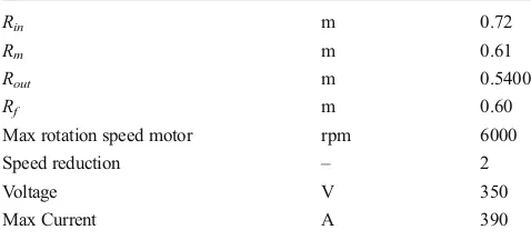
Characteristic and performance table is reported in Appendix 1, while power propulsion system is evaluat-ed in Table 1. The propeller is schematized in Fig. 5. Main dimensional parameters, which are calculated ac-cording to Trancossi et al. [31, 32], are reported in Table 2 and considering a different diameter of the fan. Installing four ducted fan units with a pressure ratio Fig. 3 Cessna 402 during takeoff
[image:7.595.51.289.52.182.2] [image:7.595.70.515.480.699.2]1.1, turbofan characteristics can be evaluated according to Mingtai [33] who suggest the relation
Ts¼1:238⋅10−12⋅n2⋅ 2Rf
4
⋅ρair⋅kt ð6Þ
where kt is the static thrust coefficient and n is the
speed of rotation of the fan.
The advantage supporting the adoption of the Cessna 402 model is the relative high number of aircraft in operation both produced by Cessna and by Sukhoi. It is an aged project, but displays good flight performance and behaviour, which is ap-preciated by pilots, and the very traditional distribution of weight in the airplane, which fits very well with the use of such propulsion also because of the construction of wings, which could allow a good integration of ACHEON derived propulsion nozzles instead of traditional propulsion.
The ducted fan units have the dimensions specified in Table1and performance specified in Table2. In particular, a turbo machine with a pressure jumpΔp = 0.3 Patmhas been
adopted.
The Cessna 402 has a thrust to weight ratio about 0.37, and a total thrust of approximately 11000 N. The proposed com-pressor units, to achieve 30 % pressure jump, require multiple stages, typical of turbo machinery. The typical compressor unit has a max thrust about 3000 N, thus there will be 4 compressor units to propel the aircraft with a max thrust about 12000 N.
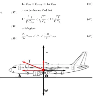
On this basis, it is possible to evaluate the system. The deflected thrust by Coanda effect is evaluated according to Keen [34], who has verified that it is almost negligible be-cause of very reduced frictional effects, and bebe-cause a very low lift is produced, in a boxed architecture of the ACHEON nozzle (Fig.6). Starting from those preliminary evaluations the aircraft system will be evaluated.
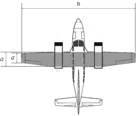
3.3 Wing characteristics
The wing planform area (S) is shaded in Fig.6. The wing taper ratio is assumed to be the ratio of tip chord (ct) to root chord
(cr),
λ¼ct
cr
ð7Þ
The mean aerodynamic chord can be found by integrating the individual section chords across the span.
c¼2
S⋅ Z b=2
0
c2⋅dy ð8Þ
In case of wings with simple linear taper. In this case, the mean aerodynamic chord will roughly equal the mean geo-metric chord,
c¼cavg¼
S
b ð9Þ
The aspect ratio of the external wing parts will be,
AR¼b
2
S ð10Þ
moreover, for the central rectangular planform this simplifies to,
AR¼b
c ð11Þ
[image:8.595.397.546.57.194.2]In the case of Cessna 402, wing area is about21 m2. Aspect ratio of Cessna 402 is 8.61.
Table 1 Ducted fan dimensions
Rin m 0.72
Rm m 0.61
Rout m 0.5400
Rf m 0.60
Max rotation speed motor rpm 6000
Speed reduction – 2
Voltage V 350
Max Current A 390
R
in
R
f
R
u
Fig. 5 Propeller schema
Table 2 Aerodynamic
parameters CD0 0.027
E 7.7
K 0.00617
CL0 0.167
CDmax 0.0338
CLmax 1.104
CLmax,carriage 0.0415
CLmax carriage 2.35
[image:8.595.50.289.70.178.2] [image:8.595.234.547.652.712.2]3.4 Lift and lift coefficient
To simplify the problem, lift is typically measured as a non-dimensional coefficient.
CL¼
L 0:5⋅ρ⋅u2⋅A
p
ð12Þ
In the normal range of operations, the variation of lift co-efficient with angle of attack of the vehicle will be approxi-mately linear,
CL¼aL⋅αþCLo¼aL⋅ðα−αoÞ ð13Þ
until a maximum lift coefficient value at which point the wing flow stalls and lift reduces.
A simple approximation for straight, moderate to high as-pect ratio wings is to assume an elliptical spanwise load dis-tribution, which gives the following result,
a¼dCL
dα ¼CLα¼
2⋅π
1þ 2
AR
ð14Þ
where it is assumed that the ideal two-dimensional result for the section used is2π.
Calculation of zero angle lift coefficient or zero lift angle can be done by crudely assuming that the zero lift angle for the aircraft equals the combination of zero lift angle of the aerofoil section and wing incidence setting. Calculation of maximum lift coefficient can be approximately equal to the two dimen-sional section data minus 5 % due to the negative lift needed at the tailplane to maintain moment equilibrium. These approx-imations works properly for the Cessna 402 because of it has almost rectangular wings.
3.5 Drag coefficient
In theory the drag can be predicted by using a simple parabolic drag assumption,
CD¼CD0þK Cð L−CL0Þ2 ð15Þ
If the offset due to camber is neglected, the following sim-plified equation can be obtained
CD¼CD0þKCL2 ð15’Þ
According to (15) and (15'), the drag is assumed with a reasonable precision as a quadratic function of lift.
The effect of compressibility can be predicted by the use of a correction factor for speeds ranging fromM= 0.4 up to tran-sonic, but in this case it can be not considered.
The lift dependant component can be approximated as
K¼ 1
π⋅Ax;yR⋅e ð16Þ
whereeis the efficiency factor of planform wing. It is indicat-ed inAppendix 1for the specific kind of aircraft.
In case of takeoff and landing, drag can be evaluated by considering that the landing gears are fully extended, increase the CD0and there is a reduction in the induced drag due to the
close proximity of the wings to the ground. The following expression is used to calculate the increase in CD0:
ΔCD;0 ¼
W S Kucm
−0:215 ð17Þ
and the drag is consequently (8'')
CD;0þΔCD;0¼CD;0þ
W S Kucm
−0:215 ð18Þ
where:
– W/S is the wing loading in unit of Newton per square meter intended primarily for use in incompressible flow conditions
– mis the maximum mass of the airplane in kilograms
– Kucis a factor that depends of the amount of flap
deflec-tion. For maximum flap deflection,Kuc= 3,16 10−5.
3.6 Flight mechanics
3.6.1 Flight analysis in a vertical plane
The lift and drag are aerodynamic forces that are defined rel-ative to the flight path. The lift is perpendicular to the flight path and the drag is along the flight path. The thrust of the aircraft is also usually aligned with the flight path. We initially b
cr ct
[image:9.595.54.290.52.251.2]assume and investigate the ideal positioning of the ACHEON nozzle to take the max advantage during take off and landing operations, assuming that it changes the angle of the thrust only during take off and landing operations.
Elementary equations of flight become (Fig.7):
X
i
Fy;i¼m⋅ay → T⋅sinc −D⋅sinc þ L⋅cosc−W ¼ m⋅ay
X
i
Fx;i¼m⋅ax → T⋅cosc −D⋅cosc þ L⋅sinc ¼ m⋅ax
ð19Þ
where lift is
L ¼ 0:5⋅CL⋅ρ
air⋅u2⋅Ax;y ð20Þ
and drag is
D¼0:5⋅CD⋅ρair⋅u2⋅Ay;z: ð21Þ
The resulting equations of motion are:
T−D
ð Þ⋅cosγ−L⋅sinγ ¼m⋅ax
T−D
ð Þ⋅sinγ þL⋅cosγ−W ¼m⋅ay
ð21’Þ
For small climb angles (<6°), thecosγis nearly 1 and the sin(γ) is nearly zero. The system of Eq. (1') then reduces to
T−D
ð Þ≅m⋅ax
L⋅cosγ−W ¼m⋅ay
ð21^Þ
Assuming that thrust can assume different angles than the trajectory of motion (Fig.8), the angle of the variable thrust respect the trajectory is defined with t. The thrust can be expressed as a function of the anglet + c, which is the sum
of the climbing angle with the angle of the thrust with the trajectory:
Tx−D⋅cosγ−L⋅sinγ ¼m⋅ax
Ty−D⋅sinγþL⋅cosγ−W ¼m⋅ay
; ð22Þ
whereTxandTyare expressed as follows:
Tx¼T⋅cosðγþtÞ
Ty¼T⋅sinðγþtÞ
: ð23Þ
The system of Eq. (23) can be expressed by assuming the internal trigonometric relations and becomes:
T⋅cost−D
ð Þ⋅cosγ−ðT⋅sintþLÞ⋅sinγ ¼m⋅ax;t T⋅cost−D
ð Þ⋅sinγþðT⋅sintþLÞ⋅cosγ−W ¼m⋅ay;t
ð24Þ
As before, for small climb angles (<6°), the termcos(c) is nearly one and the term sin (c) is null. The system of Eq. (24) then reduces to Eq. (25):
T⋅cost−D ¼m⋅ax;t T⋅sintþL−W ¼m⋅ay;t
ð25Þ
Showing clearly the contribution of the terms due to the variable direction thrust, which is positive, when thrust is di-rected upward, and negative, when thrust is didi-rected down-ward the climbing trajectory.
3.6.2 Stall analysis
The calculated the stall speeds are respectively:
ustall;t¼0¼
ffiffiffiffiffiffiffiffiffiffiffiffiffiffiffiffiffiffiffiffiffiffiffiffiffiffiffiffiffiffiffiffiffiffiffi W 0:5⋅CLmax⋅ρ
air⋅Ax;y
s
ð26Þ
Fig. 7 Forces on an aircraft
[image:10.595.232.546.55.148.2] [image:10.595.180.544.544.711.2]ustall¼ustall;t¼0⋅
ffiffiffiffiffiffiffiffiffiffiffiffiffiffiffiffiffiffi 1−T
⋅sint W r
ð27Þ
It is evident that the stall speed with upward directed thrust is lower than the stall speed in a traditional airplane, higher when thrust is directed downward.
It can be obtained thatustall= 0if
1−T⋅sint
W ¼0→sint¼ W
T ð28Þ
3.6.3 Stability analysis
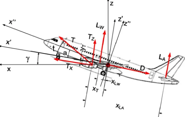
Stability analysis will allow the definition of the optimal po-sitioning of the ACHEON propulsion to achieve different goals and satisfy different mission profiles. Stability analysis is fundamental for defining optimal aircraft architecture. In flight, any aircraft will rotate about its center of gravity, a point, which is the average location of the mass of the aircraft. We can define a three dimensional coordinate system through the center of gravity with each axis of this coordinate system perpendicular to the other two axes (Fig.9).
In Fig.9, two coordinate systems have been defined:x, y, z (withxparallel to the horizontal and z vertical),x',y,z'(withx' parallel to the trajectory andz'axis orthogonal to the trajecto-ry) andx'', y, z''with (x''parallel to the aircraft fuselage axis andz''perpendicular to this axis). The angleαis the angle of attach that the fuselage forms with the trajectory. The orienta-tion of the aircraft by the amount of rotaorienta-tion of the x'',y,z'' coordinate system onx,y,zin the point G.
3.6.4 Pitch motion
The pitch axis is the y axis, perpendicular to the aircraft centreline and lies in the plane of the wings. Pitch motion is an up or down rotation around the centre of gravity.
The pitching motion is being caused by the deflection of the elevator of the aircraft. but also influenced by position where thrust is applied.
The pitch equilibrium is presented in Fig.10.
The equilibrium of torques of the aircraft is calculated around one of the significant points. Usually it is defined as the center of aerodynamic forces, but in this case due to its variation as a function of different parameters such as speed it is preferred to define the centre of mass as being nearly constant.
It can be demonstrated that the case when the thrust appli-cation point is almost coincident with the centre of gravity the action of the thrust direction change is neutral in terms of effects on the pitch. It can be also easily demonstrated that, if it is not coincident, the directional change of the thrust can be used instead of ailerons for stabilizing the aircraft.
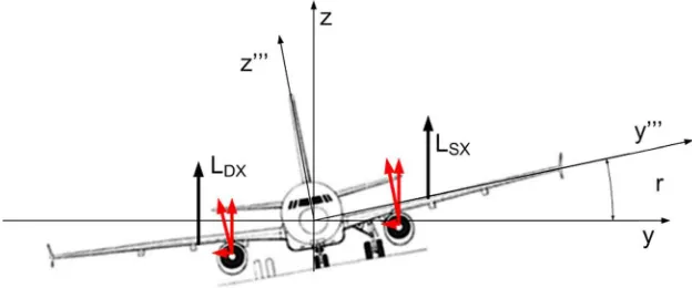
3.6.5 Roll motion
[image:11.595.51.290.53.247.2]In flight, any aircraft will rotate about its center of gravity. The roll axis lies along the aircraft centreline. The deflection of the Fig. 9 Axis of an aircraft
[image:11.595.234.543.511.706.2]ailerons of the aircraft causes the rolling motion. The aileron is a hinged section at the rear of each wing. The ailerons work in opposition; when the right aileron goes up, the left aileron goes down.
Changing the angle of deflection at the rear of an airfoil will change the amount of lift generated by the foil. With greater downward deflection, the lift will increase in the upward di-rection; with greater upward deflection, the lift will decrease in the upward direction. Since the ailerons work in pairs, the lift on one wing increases as the lift on the opposite wing decreases. Because the forces are not equal, there is a net twist, or torque about the center of gravity and the aircraft rotates about the roll axis. The pilot can use this ability to bank the aircraft, which, causes the airplane to turn. it is clear that, if variable direction propulsion, such as ACHEON, are installed, benefits could immediately arise on the roll motion control assuming that the distance of the propeller could be long enough.
Figures 11and12 shows the roll rotation with upward directed thrust and Fig.8 with downward directed thrust. Both configurations can be achieved during different flight operations.
3.7 Pull up and push over manoeuvres
Considering at this level only manoeuvres on the vertical plane, two types of flight manoeuvres are a symmetric: pull
up and push over. In either case further terms are added to define the dynamic equilibrium of flight.
For a symmetric pitch up, we conventionally assume that the vehicle is moving in a large vertical circle, even if the trajectory can present some differences. When the manoeuvre starts, the forces, in an airplane with thrust aligned with the x-axis in the vertical direction are:
L uð Þ−W ¼m⋅V
2
R ¼ W
g ⋅ V2
R ð29Þ
The forces in horizontal direction are:
T−D uð Þ ¼m⋅ac¼W
g ⋅ac ð30Þ
In the case of an inclined thrust, the equilibrium of the forces is:
L uð Þ þT⋅sint−W ¼m⋅u
2
R ¼ W
g ⋅ u2
R ð31Þ
and
T⋅cost−D uð Þ ¼m⋅ac¼W
g ⋅ac ð32Þ
[image:12.595.231.543.55.185.2]It is the clear that by deflection of the thrust lower pitch up radius can be assumed with upward directed thrust and higher with downward directed thrust.
[image:12.595.233.543.563.708.2]Fig. 11 Roll rotation with upward directed thrust
3.8 Take off and landing operations
3.8.1 Takeoff run dynamics
Figure13 represents take off operation with a directional thrust.
A well working set of equation that allows modelling take-off operations is provided by Phase [25]. It is also necessary to consider in this part the Federal Aviation Regulations that defines acceptable procedures for take off operations, FAR 25.103, 105, 107, 109, 111, 113 [35–40].. If thrust is horizon-tal and the weightW = m gthe equations of takeoff run are:
W g ⋅
du
dτ ¼T−D uð Þ−μ⋅½W−L uð Þ ¼T−Rt¼0ð Þu ð33Þ
where
Rt¼0ð Þ ¼u D uð Þ−μ⋅½W−L uð Þ ð34Þ
and
W≥L uð Þ; ð35Þ
If the thrust is directed in a direction, which is different from the horizontal, it can be obtained:
W g ⋅
du
dτ ¼T⋅cost−D−μ⋅ðW−L−TsintÞ; ð36Þ
which becomes
W g ⋅
du
dτ ¼T⋅cost−D uð Þ−μ⋅½W−L uð Þ ¼T−R uð Þ; ð37Þ
where
R uð Þ ¼Rt¼0ð Þu −μ⋅T⋅sint; ð38Þ
and
W ¼mg≥L uð Þ þT⋅sint ð39Þ
The equal condition in Eq. (39) is satisfied at the takeoff point.
The take off condition results:
W ¼L utakeoff
þT⋅sint: ð40Þ
the equilibrium in vertical direction expressed by Eq. (38) results
W ¼0:5⋅CL⋅ρ
air⋅u2takeoff⋅Ax;yþT⋅sint; ð41Þ
that allows calculating the take off speed, which results in the case oft = 0,
utakeoff;t¼0¼
ffiffiffiffiffiffiffiffiffiffiffiffiffiffiffiffiffiffiffiffiffiffiffiffiffiffiffiffiffiffi W 0:5⋅CL⋅ρair⋅Ax;y
s
ð42Þ
and in the case of directional thrust it becomes
utakeoff ¼utakeoff;t¼0⋅
ffiffiffiffiffiffiffiffiffiffiffiffiffiffiffiffiffiffi 1−T⋅sint W r
: ð43Þ
Equation (43) demonstrates clearly that the take off speed is lower than the one witht= 0 in the case thatt> 0, or thrust is oriented upward, and higher in the case that thrust is oriented downward.
Usually the takeoff speed is higher than stall speed at ground level. It is usually assumed that:
1:1⋅ustall ¼utakeoff ¼1:2⋅ustall ð44Þ
it can be then verified that
1:1 ffiffiffiffiffiffiffiffiffiffiffi
1 CLmax
s <
ffiffiffiffiffiffi 1 CL
r
<1:2 ffiffiffiffiffiffi
1 CL
r
ð45Þ
which gives
25
36CLmax<CL< 100
[image:13.595.233.546.387.711.2]121CLmax: ð46Þ
An effective analysis of the detachment phase can be per-formed after the analysis of the ground-based run after take off.
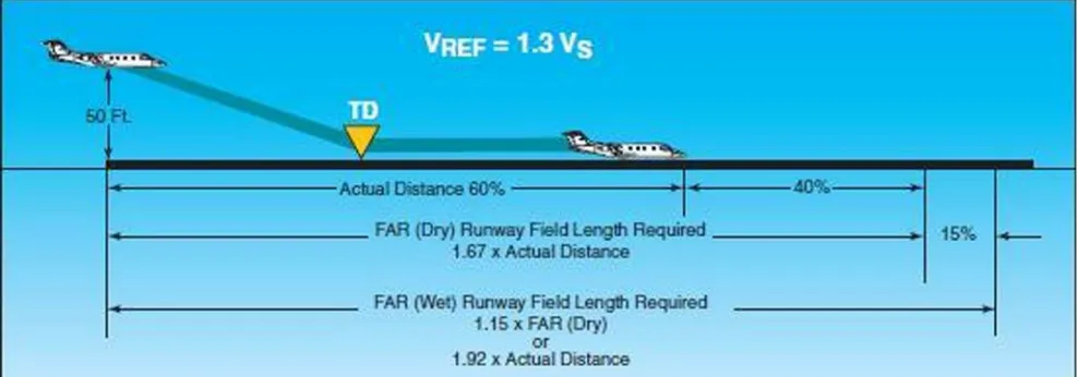
3.8.2 Detachment from the ground
After the preliminary ground run the most critical phase of the plane behaviour is the detachment phase, which is regulated by FAR standards (Fig.14). Take off is concluded only when an airplane has reached an height of 10 m. Assuming the hypothesis that during this phase the velocity does not change significantly and remains almost constant .
The radius of curvature can be calculated by Eqs. (33) and (34). In the case of assumingutakeoffconstant, they becomes
respectively:
Rt¼0¼ L utakeoff;t¼0
−W
⋅ g
W⋅u2
takeoff;t¼0
ð47Þ
R¼ L utakeoff
þT⋅sint−W
⋅ g
W⋅u2
takeoff
ð48Þ
it can be demonstrated that the most interesting condition is
R Rt¼0
≤0→ L utakeoff
þT⋅sint−W
L u takeoff;t¼0−W
⋅
u2takeoff;t¼0
u2 takeoff
≤0 ð49Þ
After this operation, the motion continues with a climb.
3.8.3 Landing operations
Landing operations can be modelled in a similar way and are almost symmetrical (Fig. 15). In this case FAR 25.119 -Landing climb all engines [41], and FAR 25.125 - -Landing [42] applies. Landing operations can be described assuming an initial push over manoeuvre, which starts at cruise speed ucruiseand can be modelled in both cases respectively:
Rt¼0¼−L u cruise;t¼0þW⋅
g W⋅u2
cruise;t¼0
ð50Þ
R¼ð−L uð cruiseÞ−T⋅sintþWÞ⋅
g W⋅u2
cruise
ð51Þ
In the case of Eq. (49) with directional thrust, it is evident that the same radius can be obtained in two modes: a low lift configuration with higher vertical thrust component, or a higher lift configuration and lower vertical thrust component, but also with a downward directed thrust, without changing the aircraft configuration.
The following manoeuvre is the climb down, with deceler-ation to a velocity, which is about touch down speedulanding. It
is in the range
1:2⋅ustall ¼ulanding¼1:3⋅ustall: ð52Þ
Usually a value of 1.23 ustallis adopted.
uland¼uland;t¼0⋅
ffiffiffiffiffiffiffiffiffiffiffiffiffiffiffiffiffiffi 1−T⋅sint W r
[image:14.595.51.546.376.700.2]: ð53Þ
In this case, a much lower landing horizontal speed can be ensured:
−0:5⋅CD⋅ρair⋅u2
down⋅Ay;z−T⋅cost−wcosγ ð54Þ
whereγis the climbing angle.
In particular, it assumes vertical configuration when
m⋅ay¼−Wþ0:5⋅CD⋅ρ
air⋅u2down;y⋅Ax;y−T⋅sint
−0:5⋅CD⋅ρ
air⋅u2down;x⋅Ay;z−T⋅cost
ð55Þ
The final manoeuvre before touching the ground is a fur-ther rotation with centre higher than the trajectory starting at 50 ft (15.24 m) with radius:
Rt¼0¼ L uland;t¼0
−W
⋅ g
W⋅u2
land;t¼0
ð56Þ
R¼ðL uð landÞ þT⋅sint−WÞ⋅
g W⋅u2
land
ð57Þ
In addition, in this case operations could be per-formed by different combinations of vertical thrust and lift force, including fixed aerodynamic configurations governed simply by jet.
It can be then possible to model the final part. If the thrust is directed in horizontal direction or in a direction, which is different from the horizontal, it can be obtained:
W g ⋅
du
dτ ¼Tcost−D−μbrake⋅ðW−LþTsintÞ; ð58Þ
whereμbrakeis the friction coefficient during braking phase.
In this case, some thrust directed vertically can be interest-ing. Braking space can be easily evaluated as in the case of the takeoff run.
3.9 Aircraft configuration
The aircraft configuration has been studied subject to the air-craft performance and required power for different operations. A complete analysis of the performances of the modified Cessna 402 plane will be performed against the traditional plane with propellers [43]. In particular, Fig. 16shows the airplane configuration with a section on the ACHEON pro-peller illustrating the main positioning of the system.
[image:15.595.51.545.55.228.2]Figure17shows the detail of the ACHEON nozzle section and its configuration so to allow a better comprehension of its behaviour. In particular, the proposed model presents a limi-tation in angular terms of the jet, to allow an effective predic-tion of the maximum angle, which could be reached. Fig. 15 Landing profile and critical velocity as identified by FAR
[image:15.595.236.545.603.710.2]t
To simplify the model controls and to ensure a better inte-gration with the airplane configuration a positioning of the geometric centre of thrust coincident with the centre of gravity will be considered. Otherwise, it is evident that torque com-ponents could be introduced with negative consequences on the aircraft behaviour. The application of the centre of thrust rotation in the centre of gravity could is also considered to increase the safety of the system and allowing an adequate system behaviour in case of technical problems.
In particular, there will be assumed three limiting positions:
– an angle =0ensured by top jet (horizontal flight);
– an angle =tensured by both jets (take off);
– an angle =2 tensured by bottom jet (landing).
Different angles t could apply, as demonstrated by the pro-ject activities. they space in a range12 ÷ 25°. The effects will be evaluated for some specific angles, while jet velocity and regimes will be defined according to specific conditions.
Energetic and environmental evaluations will be also performed.
3.10 Mission profile
To describe the results a specific mission will be considered. The typical mission profile is defined according to the FAR standards for commercial vehicles.
In some operations, different operative methods will be taken into account and will be compared. The analysis will also consider FAR standards to verify the suitability of the system for future application into aviation. Further consider-ations will regard the possible modificconsider-ations, which could be
necessary to the FAR to allow ACHEON integration. ACHEON will be also preliminarily evaluated against EC Reg. No. 216/2008 [25], identifying future certification needs for flying in Europe. A typical mission profile is illustrated in Fig.18.
4 Results
The results will be compared to the effective performance of a Cessna 402 identifying improved and degraded operation. Energy and performance related considerations would be per-formed focusing on the specific effects of the all-electric ACHEON propulsion system.
Further consideration will regard the necessity of further improvements, which could be necessary for implementing in ACHEON. It is assumed to use the same aerodynamic configuration, which is used for the traditional version and equal thrust condition.
The main parameters of the aircraft have been preliminarily calculated [27–30, 44]. The propulsion model is shown in Fig.19. The lift and drag data are calculated and reported in Table2and the engine data inAnnex, will be used as models of the aircraft and engine.
A concrete/asphalt runoff is assumed with a friction coef-ficient0.02for takeoff and landing operations.
4.1 Take off evaluation
The following data can be assumed by FAR Part 25 (Table3). Simplified takeoff profile is assumed Main data have been reported in Tables4and5.
2t
t
[image:16.595.230.544.55.151.2]G
[image:16.595.178.544.598.712.2]Fig. 17 Nozzle positioning and limiting thrust vector directions
The values in Table 6 have been calculated during takeoff, considering that the average speeds during these operations has been evaluated at 0.71 utakeoff [45]. It is
the first part of the takeoff it relates to the following phases transition a screen up to 35 ft (10 m) has been considered, as specified by FAR Part 25. Maximum ini-tial vertical speed of 7.6 m/s is assumed for the CESSNA 402 and it results after take off. It means that the initial average horizontal speed is 52.7 m.
Energy requirements for take off includes also taxi time, wait and run, according to FAR Part 25. Ten minutes operation time has been estimated. .
Advantages in terms of energy saving are evident at each angle of the takeoff length. It can be verified that if a well defined load factor has been assumed during operations that could not exceed 1, adequate comfort of the passengers is ensured,
n¼L=W; ð59Þ
which becomes for ACHEON propelled airplanes
n¼ðLþT sin tÞ=W≤1; ð60Þ
that constitutes a precise limit to aerodynamic loading in func-tion of the thrust.
L≤W−T sin t ð61Þ
It shows clearly that the flight assist can be ensured in two ways:
1. by changing lift maintaining directional thrust;
2. by changing thrust direction maintaining aerodynamic
lift.
The other evident result is that the same take off perfor-mance could be also obtained with a much-reduced aerody-namic lift and then a lower drag.
4.2 Climb
It is assumed that the plane at the end of takeoff segments up to 10,000 ft (3048 m) reaches the cruise speed (109 m/s).
After the transition phase there is a slow transition from the dual jet configuration to allow the jet to adhere to the upper surface, as shown in Fig.19, but also a climb with inclined Thrust can be performed. An angle of attach of 7 has been considered.
The difference in terms of accelerations between the two solutions is evident by subtracting the system of Eqs. (13) and (15).
m⋅ax;t−ax
¼T⋅cost⋅cosc−T⋅sint⋅sinc−T⋅cosc¼T⋅cosðcþtÞ−T⋅cosc<0
m⋅ay;t−ay
¼T⋅cost⋅sincþT⋅sint⋅cosc−T⋅sinc¼T⋅sinðcþtÞ−T⋅sinc>0
ð62Þ
It is clear the difference of accelerations along x-axis is reduced, while the one along y-axis is increased.
Average speed during climb can be evaluated in different configurations:
An average climb rate of6.7 m/shas been assumed. About 40 kWh(144000 kJ) are necessary in all the configurations. Expected energy consumption is about140 kWh(504000 kJ) for traditionally propelled aircraft and about 53 kWh (191000 kJ) for electric ones.
4.3 Horizontal Flight
Flight will is estimated considering the above model and stan-dard atmospheric data at 1000 m. An average angle of attach-ment of 3° has been assumed, even if a twin engine aircraft in cruise could also fly with horizontal axis. Consumption for 1 h flight at1000 m and cruise velocity is expected to be1060 kWh (3816000 kJ) for traditional propulsion and about360 kWh(1296000 kJ) for the electrical one only because of in-creased efficiency of electric propulsion. In the case of hori-zontal flight electric propelled airplane there is no mass reduc-tion and this aspect must be considered during landing operations.
2t t
G
CRUISE FLIGHT
Power 50%
TAKEOFF
Power 100%
LANDING
[image:17.595.53.291.54.148.2]Power 50%
Fig. 19 Preferential use of different configurations during different flight operations
Table 3 FAR Part 25 optimal takeoff and landing parameters
Flight Condition: Number of Engines
4 3 2
First Take-Off Segment 0.5 % 0.3 % 0.0 %
Second Take-Off Segment 3.0 % 2.7 % 2.4 %
Final Take-Off Segment 1.7 % 1.5 % 1.2 %
Enroute Climb 1.6 % 1.4 % 1.1 %
Approach Segment 2.7 % 2.4 % 2.1 %
[image:17.595.51.290.587.711.2]4.4 Landing
Landing energy needs can be evaluated according to usual twin-engine general aviation aircraft. Typical angle and air-speed during landing are presented in Table6.
Landing modes have been presented in Fig.20assuming a traditional 3° glideslope. Figure20shows instead the com-plete landing manoeuvre considered. It is clear that gliding takeoff requires low energy consumption. A 3° degree glideslope for a traditional Cessna 402 will require a landing space, which can be calculated and against the value of 757 m (declared by the producer). Calculations give a worst result of about763 m, which is acceptable because of the necessary approximations in calculations.
Data between the descent phase and landing using ACHEON can be assumed adopting a different profile (Table7).
Different profiles of climbing have been considered for ACHEON propelled aircraft. They can be ensured by hybrid combination of vertical component of the thrust, when
adhering to the lower surface and aerodynamic lift. In this case the thrust in vertical direction could be almost equal to the one during takeoff, while the horizontal one is much reduced. Angle of attack is considered the same as above. Considering different stall speeds and maximum deceleration about 3 m/s both spaces and times for landing operations have been calculated. Results are presented in Table8.
It is now evident that ACHEON can also perform better performances in case of landing.
4.5 Further ACHEON system improvements
[image:18.595.175.545.60.151.2]The ACHEON propulsion system can be improved by opti-mizing the inlet by an effective improvement of the inlet sec-tion, as verified by Trancossi and Madonia [46]. By optimiz-ing the air intake design it can be possible to increase the propulsive efficiency especially at high altitude. But this level of optimization it is not performed at this level because it requires a more effective design activity.
Table 4 Flight behaviour
Angle of Attack Angle of Climb Pitch Attitude Incidence Airspeed
Initial roll 4.5∘
0∘
0.0∘
4.5∘
Small, incr. After rotation 12.0∘
0∘
7.5∘
4.5∘
increasing At liftoff 12.0∘
0∘
7.5∘
4.5∘
6 % belowVY
Initial climb Decr. incr. 7.5∘
4.5∘
increasing Steady climb 7.0∘
5∘
7.5∘
4.5∘
10 % aboveV
Table 5 Takeoff comparison between tradional Cessna 402 and Cessna 402 with ACHEON with different angles of inclination
Propellers ACHEON
Angle of deflection 15° 10° 5° 0°
Direction of Tx Ty Tx Ty Tx Ty Tx Kg
Thrust 5185.2 5009 1342 5106 900.4 5166 451.9 5185 kW
Max Power 280 280 m/s
ustall 46.3 26.3 32.9 39.5 46.3 m/s
ustall,carriage, down 31.74 18 22.6 27.1 31.7 Kg
Take off mass 3105 3105 m/s
Lift Off Speed 50.93 28.93 36.19 43.45 50.93 m/s
Take off Speed 55.56 31.56 39.48 47.4 55.56 m
Liftoff Length 641.5 206.8 323.4 468.4 690 m
Takeoff Length (calculated)
690 222.4 347.8 503.8 690 m
Take off length declared 670 m/s
Lift Off Time 16.5 9.48 11.9 14.32 16.5 S
Take Off Time 17.74 10.2 12.8 15.4 17.74 kJ
Energy needs 132012 27468 31068 34668 44280 kJ
Energy saving 0 104544 100944 97344 87732
[image:18.595.179.546.450.712.2]4.6 Energy analysis
This analysis focuses on the energy analysis of the electrical ACHEON propelled Cessna 402 against the model on the market [47, 48]. This analysis produces some interesting results.
In particular, the energy comparison are presented in Table9. An emergency reserve higher than 15 % is assumed to ensure some minutes flight for the electric ACHEON Propelled aircraft then the time for flight at cruise condition could not exceed 20 min for electric ACHEON propelled plane.
It can be verified that the original configuration is not ad-equately performing in terms of autonomy and energy storage. A better energy efficiency and cruise performance of the ACHEON propelled aircraft can be obtained by decreasing cruise speed to about 324 km/h (90 m/s). Data in this case indicates increase to 40 min cruise speed.
Assuming average European electric production efficiency [49], which has been estimated about 50 % in 2010, the effec-tive energy demand will be about double than declared con-sumptions, but much lower than the one for the conventional engine.
4.7 Improving the airplane configuration
Improved performance can be ensured by equipping the plane by an electric lightweight cogeneration system coupled to heat recovery system. Assum Rolls Royce-Allison Model 250 C20R turboprop [49] with a max nominal power of about 190 kWand continuous power about170 kW (602.5 MJ) is considered [50]. It has a weight of62 kgdry (0.32 kg/kW).
Considering all the necessary accessories a weight about 1.2 kg/kW can be conservatively assumed, including the heat recovery system. Assuming the hypothesis of recov-ering heat from the turboprop and converting it by heating the fluid flow, preliminarily conceived by Trancossi [31], patented by Dumas et al. [51] and studied by Trancossi et al. [32]. Using the same calculation methodology used by Trancossi et al., thermal emission can be calculated by considering consumption about 0.48 kg/kWh and a con-servative global thermal exchange efficiency about 0.4. The amount of recovered heat per hour is then 338.65 kWh(1220 MJ).
It means an increase in terms of thrust about 30 % that means a reduction of required electrical power about54 kW.
This new condition enables flight with a partial system redefinition and general improve, with overall energy efficien-cy about three times the one of the traditional airplane.
In this case, it can be assumed the following configuration 250 kg of fuel, 250 kgcogeneration system and 1050 kg batteries.
This configuration could allow flight endurance about 6 h with a sufficient reserve,
This result is also interesting because the heat exchanger produces some losses but can be also used as a stator for straightening the jet as demonstrated by Shyam and Trancossi, which increases the adhesion, but also a positive thermal difference is a benefit because of an increased adhe-sion capability as demonstrated by Subhash in his thermal analysis.
[image:19.595.176.545.60.177.2]The resulting configuration is summarized in Table10. The operational reduction of payload, which has been as-sumed in previous all electric architecture is maintained. Table 6 Landing parameters
according to FAR25 Airspeed (KCAS) Pitch Attitude Incidence Angle of Climb Angle of Attack
Cruise (clean) 100 ÷ 120 0.0° 4.5° 0.0° 4.5°
Level VY (clean) 70 4.0° 4.5° 0.0° 8.5°
Level (flaps) 70 0.0° 8.5° 0.0° 8.5°
Slower (flaps) 65 2.0° 8.5° 0.0° 10.5°
Descent (flaps) 65 −2.0° 8.5° −4.0° ÷−6.0° 10.5°
Flare (flaps) decr. incr. 8.5° incr. incr.
[image:19.595.51.542.629.701.2]Stall (flaps) 46.3 12.0° 8.5° 0.0° 20.5°
5 Conclusions
This paper has clearly demonstrated the benefits of the ACHEON nozzle applied to the propulsion of a commuter class transport twin-engine aircraft. The choice has been fo-cused on the Cessna 402 aircraft because its geometric con-formation, which could easily allow a positioning of the ACHEON nozzle with centre of thrust almost coincident with centre of mass. The paper produces the basic con-trol equations of an aircraft with this singularity show-ing the benefits of variable direction thrust applied in this position.
For simplicity only three positions have been considered, because they seems the state that can be easily produced at this level of research activity. They are full thrust (two fans on) with an angle t of inclination (with tcomprised between0° and15 °. A nozzle with opening equal to t so that two extreme positions could be stabile:
& 0° for horizontal flight, with higher jet near 100 % ant the other below 50 %.
[image:20.595.179.544.58.226.2]& 2 t for takeoff operations to sustain the airplane during operations with lower jet about 100 % and lower below 50 %.
Table 7 Landing, Airspeeds and
Angles with ACHEON Airspeed
(KCAS)
Pitch Attitude
Incidence Angle of Climb
Angle of Attack
Cruise (clean) 100 ÷ 120 0.0° 4.5° 0.0° 4.5°
Level VY (clean) 70 4.0° 4.5° 0.0° 8.5°
Level (flaps) 70 0.0° 8.5° 0.0° 8.5°
Slower (flaps) 40÷65 2.0° 8.5° 0.0° 10.5°
Descent (flaps) 40÷65 −2.0° 8.5° −3.0°÷−12.0° 10.5°
Flare (flaps) decr. incr. 8.5° Incr. incr.
Stall (flaps) for different angles of thrust (half power angle)
0° 0° 46.3 12.0° 8.5° 0.0° 20.5°
5° 10° 39.5 12.0° 8.5° 0.0° 20.5°
10° 20° 32.9 12.0° 8.5° 0.0° 20.5°
15° 30° 26.3 12.0° 8.5° 0.0° 20.5°
Table 8 Landing performances
in different configurations Inclination of the nozzle
15 10 5 0°
Nozzle angle 15 10 5 0° deg
Direction of thrust 30 20 10 0 deg
Tx Ty Tx Ty Tx Ty Tx
Thrust 2245.17 1296.25 2436.15 886.69 2553.11 450.18 2592.50 kg
Max Power 140 kW
ustall 26.3 32.9 39.5 46.3 m/s
ustall,carriage, down 18 22.6 27.1 31.7 ù
Landing mass 3105 kg
Gliding Speed 32.875 41.125 49.375 55.56 m/s
Touch down Speed 28.93 36.19 43.45 50.93 m/s
Landing Space (calculated)
431.71 540.04 648.38 760 m
Average landing acceleration
2.03 2.03 2.03 2.03 m/s2
Landing Time 14.25 20.26 24.32 2.00 s
Ground roll Time 14.25 17.83 21.40 25.09 s
Braking Energy 2598.71 4066.67 5861.94 8053.95 kJ
Braking energy 1559.23 2440.00 3517.16 4832.37 kJ
Braking Energy saving
3273.14 2392.37 1315.21 0 kJ
[image:20.595.179.544.435.714.2]Kinematic and dynamic main parameters have been esti-mated during critical operations such as take off and landing verifying the benefits produced by the ACHEON nozzle in different flight condition. It appears fundamental, even if not directly presented in the paper, the importance of DBD to
ensure an effective governable transition between the posi-tions to avoid both too fast modificaposi-tions of the airplane be-haviour with potential stability problems and the actual con-sidered capacity of producing thrust in three well-defined directions.
In particular, further application could benefit from the pre-liminary definition of a possible single jet architecture, which aims to reduce the problems derived from high frontal section required by the dual jet configuration.
A preliminary airplane configuration equipped by high per-formance batteries is presented.
Energetic evaluations have been performed demonstrating clearly the advantages of the proposed all electric system cause of much higher energy conversion efficiency and be-cause of the possibility, which has been presented to define a cogeneration airplane architecture equipped by a Rolls-Royce Model 250 turboprop based cogeneration unit. The large dis-posability in terms of heat to be dispersed could ensure the possibility of producing a more effective propulsion effect by using them to heat the jets produced by the ducted fans.
The clear advantages of the cogeneration based solution against the battery only one is evident demonstrating the pos-sibility of an effective applicability of ACHEON all electric propulsion in the future, with a cogeneration based propulsion architecture.
In conclusion, this paper demonstrates the benefits of ACHEON based architecture to civil aircrafts ensuring en-hanced performance. Even if it is not still sufficient for future ACHEON equipped aircrafts it is a preliminary basis for con-tinuing the studies on ACEHON through a novel class of all electrical high performance aircraft, which could not been conceived before this revolutionary project.
[image:21.595.181.545.63.230.2]Acknowledgments The present work has been performed as part of ACHEON Project | ACHEON Project - Aerial Coanda High Efficiency Orienting-jet Nozzle project, with ref. 309041 supported by European Union through the 7th Framework Programme (www.acheon.eu). Table 9 Energy performances
Configuration
Cessna 402 Cessna 402 ACHEON
Flight Condition: traditional 15° 10° 5° 0°
Take-Off 132012 27468 31068 34668 44280 kJ
Second Take-Off Segment 504000 139100 kJ
Enroute (30 min) 1908000 636000 kJ
Approach Segment 267120 53000 kJ
Landing Segment 396036 8240 9320 10400 13284 kJ
Energy consumption 3207168 863808 868488 873168 885664 kJ
Max on board energy 0 1229580 kJ
Reserve −3207168 365772 361092 356412 343916 kJ
Table 10 Modified Cessna 402 Cogeneration Architecture for high energy performances
Empty weight Lb 4,069
Useful load Kg 662
Max takeoff weight Kg 3107
Max on board fuel Batteries (Boston Power Swing® 5300 Rechargeable Lithium-ion Cell)
Kg 1050
Wh/kg 207
Ah 4,420
Fuel
Kg 640
Propulsion
Cogen Rolls Royce Model 250
Power kW 250
Mass Kg 250
Motor Four Plettemberg Nov. 150 mounted in two ACHEON Nozzle
Power kW 150
Mass Kg 11.5
Performances
Max speed m/s 118.9
Max cruising speed m/s 109.4
Stall Speed m/s 46.3
Stall Speed Carriage m/s 25.1
Initial rate of climb m/s 7.366
Service ceiling M 8200
Long range cruising speed m/s 84.4 Range with reserves at
economical cruising speed
[image:21.595.49.286.356.707.2]Annex
Open AccessThis article is distributed under the terms of the Creative C o m m o n s A t t r i b u t i o n 4 . 0 I n t e r n a t i o n a l L i c e n s e ( h t t p : / / creativecommons.org/licenses/by/4.0/), which permits unrestricted use, distribution, and reproduction in any medium, provided you give appropriate credit to the original author(s) and the source, provide a link to the Creative Commons license, and indicate if changes were made.
References
1. Sehra AK (2003) Novel propulsion and power concepts for 21st century aviation. AVT Spring 2003 Symposium and Panel Business Week, Brussels
2. Trancossi M, Dumas A (2011) ACHEON: Aerial Coanda high efficiency orienting-jet nozzle. Sae Technical Papers N. 2011-01-2737, ISSN 0148–7191
3. Cen Z, Smith T, Stewart P, and Stewart J. Integrated flight/thrust vectoring control for jet-powered unmanned aerial vehicles with ACHEON propulsion. Proc Inst Mech Eng Part G: J Aerospace Eng 0954410014544179, first published on July 29, 2014 doi:10. 1177/0954410014544179
4. Trancossi M (2011) An overview of scientific and technical litera-ture on coanda effect applied to nozzles. SAE Technical Papers N. 2011-01-2591, ISSN 0148–7191
5. Baffigi F, Dumas A, Giuliani I, Madonia M, Trancossi M (2014) Ugello capace di deviare in modo dinamico e controllabile un getto sintetico senza parti meccaniche in movimento e relativo sistema di controllo. Patent IT 0001406404, Deposito RE2011A000049, Filling date July 01, 2011, Publication date September 30, 2011, approved on February 21, 2014
6. Baffigi F, Dumas A, Giuliani I, Madonia M, Trancossi M (2014) Nozzle capable of deviating a synthetic jet in a dynamic and con-trollable manner with no moving mechanical parts and a control system thereof. PTC Patent WO2013005132 A1, Publication date Jan 10, 2013, Filing date Jun 25, 2012, Priority date Jul 1, 2011, Published also as EP2726213A1, US20140191059
7. Trancossi M, Dumas A (2011) Coanda syntetic jet deflection appa-ratus and control. SAE Technical Papers N. 2011-01-2590 8. Trancossi M, Dumas A (2011) ACHEON: Aerial Coanda High
Efficiency Orienting-Jet Nozzle. Sae Technical Papers N. 2011-01-2737
9. Cattafesta LN, Sheplak M (2011) Actuators for active flow control. 43(1): 247–272
10. Xisto C, Páscoa J, and Oliveira P (2013) Modelling plasma flow on a self-field MPD thruster using a PISO based method. 44th AIAA Plasmadynamics and Lasers Conference, San Diego, USA 11. Dragan V (2014) Reynolds number calculation and applications for
curved wall jets. INCAS Bull 6(3):35–41
12. Dumas A, Pascoa J, Trancossi M, Tacchini A, Ilieva G, Madonia M (2012) Acheon project: A novel vectoring jet concept. Proc. ASME. 45172; Volume 1: Advances in Aerospace Technology: 499–508, IMECE2012-87638
13. Trancossi M, Dumas A, Vucinic D (2013) Mathematical modelling of coanda effect. SAE Technical Paper 2013-01-2195, doi:10.4271/ 2013-01-2195
14. Drăgan V (2012) A New mathematical model for Coandăeffect
velocity approximation. INCAS Bull 4:85–92
15. Subhash M, Dumas A (2013) Computational study of Coanda ad-hesion over curved surface. SAE Int J Aerosp 6(1):260–272. doi:
10.4271/2013-01-2302
16. Dumas A, Subhash M, Trancossi M, Marques JP (2014) The influ-ence of surface temperature on Coanda effect. Energy Proc 45:626– 634
17. Das SS, Abdollahzadeh M, Pascoa JC, Dumas A, Trancossi M (2014) Numerical modelling of Coanda effect in a novel propulsive system. Int J Multiphys 8(2):181–201
[image:22.595.49.288.100.586.2]18. Trancossi M, Subhash M, Angeli D (2013) Mathematical modelling of a two streams Coanda effect nozzle. ASME Int. Mech. Engg. Conf. and Exhibition, paper no. IMECE2013-63459
Table 11 Aircrat data sheet
Geometric data
Wing span m 13.45 Ft 44.2
Length m 11.09 Ft 36.5
Height m 3.49 Ft 11.6
Wing Area m2 21 Sq ft 225.8
Aerodynamic constants
CD – 0.026
E – 0.85
CLmax – 2.27
Weights
Empty weight kg 1845 Lb 4,069
Useful load kg 1262 Lb 2,783 kg 662 lb 1459.46
Max takeoff weight kg 3107 Lb 6,850
Max on board fuel kg 640 Gal 213 Batteries (Boston Power Swing® 5300 Rechargeable Lithium-ion Cell) kg 1550 Wh/kg 170 Ah 4,420 Propulsion
Engine Two 240 kW (325 hp) turbocharged and fuel injected TSIO-520-VBs
Four Plettemberg Nov. 15 mounted in two ACHEON Nozzle
Power kW 240 Hp 325 kW 150 hp 203
Weght kg 219.5 Lb 484 kg 11.5 lb 25.4
Performances
Max speed m/s 118.9 Kts 230
Max cruising speed m/s 109.4 Kts 213
Stall Speed m/s 46.3 Kts 71.4
Stall Speed Carrriage
m/s 25.1 Kts 48.9
Initial rate of climb m/s 7.366 ft/min 1,450
Service ceiling m 8200 Ft 26,900
Long range cruising speed
m/s 84.4 Kts 164 To be calculated
Range with reserves at economical cruising speed