Effects of Pore Morphology and Bone Ingrowth on Mechanical Properties
of Microporous Titanium as an Orthopaedic Implant Material
Huanlong Li
1;*1, Scott M. Oppenheimer
2;*2, Samuel I. Stupp
2,
David C. Dunand
2and L. Catherine Brinson
11Department of Mechanical Engineering, Northwestern University, Evanston, IL 60201, U.S.A. 2Department of Materials Science and Engineering, Northwestern University, Evanston, IL 60208, USA
Successful bone formation which leads to functional osseointegration is determined by the local mechanical environment around bone-interfacing implants. In this work, a novel porous titanium material is developed and tested and then impact of porosity on mechanical properties as a function of bone ingrowth is studied numerically. A superplastic foaming technique is used to produce CP-Ti material with rounded, interconnected pores of 50% porosity; the pore size and morphology is particularly suitable for bone ingrowth. In order to understand the structure-property relations for this new material, a numerical simulation is performed to study the effect of the porous microstructure and bone ingrowth on the mechanical properties. Using ABAQUS, we create two-dimensional representative microstructures for fully porous samples, as well as samples with partial and full bone ingrowth. We then use the finite element method to predict the macroscopic mechanical properties of the foam,e.g., overall Young’s modulus and yield stress, as well as the local stress and strain pattern of both the titanium foam and bone inclusions. The strain-stress curve, stress concentrations and stress shielding caused by the bone-implant modulus mismatch are examined for different microstructures in both elastic and plastic region. The results are compared with experimental data from the porous titanium samples. Based on the finite element predictions, bone ingrowth is predicted to dramatically reduce stress concentrations around the pores. It is shown that the morphology of the implants will influence both macroscopic properties (such as modulus) and localized behavior (such as stress concentrations). Therefore, these studies provide a methodology for the optimal design of porous titanium as an implant material.
(Received October 27, 2003; Accepted December 24, 2003)
Keywords: porous titanium, bone implant, finite element analysis, mechanical properties, bone ingrowth, stress shielding, morphology
1. Introduction
Titanium and its alloys are widely used as biomaterials for bone implant in dental and orthopaedic applications because of their high static and fatigue strength, low modulus, light weight, superior biocompatibility and enhanced corrosion resistance compared with other conventional biomaterials.1) To achieve long-term fixation, biomaterial implants capable of interacting more effectively with their environment have become the new focus of bone engineering, unlike passive, bioinert materials.1,2) In our work, porous titanium is proposed as an outstanding biomaterial structure that can achieve a stable bone-implant interface and has excellence biological and mechanical properties. However, the impact of the porosity, spatial distribution and morphology of the pores on the mechanical and biological properties of the metal foam are all critical to understand the behavior of the titanium foam and to optimize the morphology for bone ingrowth and orthopaedic applications.3)
There are several major approaches to model and predict the response of porous materials: composite material ap-proaches, where the included phase has a modulus of zero;4,5) cellular mechanics methods based on beam theory and cell wall structure;6) and finite element unit cell approaches, which can be equally applied for porous or composite materials. The power of the latter category was demonstrated by the landmark study by Needleman and Suresh in which the deformation characteristics of ceramic whisker- and
partic-ulate-reinforced metal-matrix composites were explored and the influence of microstructure examined.7,8) The 3D-MP (multi-particles) method9)documented the differences in 3D and 2D finite element unit cell approaches for particulate composites. In addition to the Unit Cell model, the fine 2-D spring network,10) VCFEM (Voronoi Cell Finite Element model)11)also provide alternate methods of Finite Element analysis for porous materials.
Earlier work has utilized these techniques to examine porous titanium samples of different porosity and provide values for their Young’s moduli and Possion ratios.12,13) Approaches from each of the three categories were explored to predict the elastic material properties and compare them to experimental data, including cellular solid methods,6) micro-mechanics methods,4,14) and finite element analysis. It was demonstrated that the finite element approach provided the richest information on the material mechanics as local stress fields can be evaluated and the material microstructure is more accurately represented. However, this previous work did not explore the impacts of altered pore morphology on the material response, nor did it address the important issue of localized plasticity.
Very recent work has also examined the viability of a low porosity (25%) Ti foam for in vitro cell growth.15)The results demonstrate that Ti foams coated with organoapatite pro-moted cell colonization and ingrowth. Predictions of the stress shielding effect were also made for solid implants, porous implants and porous implants with bone ingrowth, with the stress shielding effect reduced in both porous cases. The results indicate that a Ti foam with a higher porosity would both enhance the cell ingrowth and more significantly reduce the stress shielding effect. As the porosity increases however, issues of localized plasticity and the effect of pore *1Graduate Student, Department of Mechanical Engineering, Northwestern
University
*2Graduate Student, Department of Materials Science and Engineering,
Northwestern University
Special Issue on Frontiers of Smart Biomaterials
morphology become increasingly important.
Unlike aluminum foams, titanium foams cannot be produced in the liquid state, due to the high melting point and high contamination susceptibility of titanium. Existing processes are based on powder metallurgy and can be classified into two groups. First, in powder sintering processes, loose Ti powders are partially sintered or hot-pressed into a porous body.16–18)A variation on this approach mixes a temporary space-holder to the Ti powders to create large pores; after the removal of the space-holder, the Ti powders are fully sintered to create the struts of the foam.19,20) Second, in the pore expansion processes, argon gas is entrapped in a Ti body during hot-compaction of Ti powders; the resulting argon bubbles are then expanded by exposure to high temperature, where the densified Ti matrix creeps rapidly.21–24)An improvement of this process utilizes superplasticity in the matrix during pores expansion, allow-ing for higher porosity and faster foamallow-ing rates.25–27)
This paper describes the effect of the pore morphology and bone ingrowth on the mechanical properties of an unalloyed titanium foam with mid-range porosity of 44% produced by superplastic pore expansion. Foams with porosity in this range potentially offer an ideal compromise between reduced modulus (with high porosity) and known structural stability (with low porosity) for bone implant applications. The porosity level significantly reduces the modulus and weight of the implant over that of solid Ti or low porosity materials and at the same time offers more surface area and better connected pores for bone ingrowth. However, due to the close proximity of pores, mechanics issues of stress concen-trations and local plasticity need to be examined.
Finite element analysis is used to isolate the effect of the pore size, shape and position from other factors. Since processing techniques allow some measure of control over pore size uniformity and distribution, the results can help guide future material design. Previous results indicated that bone ingrowth could mitigate the stress concentrations inherent to the presence of pores.12,13,15)Therefore the finite element simulations also examine the effect of partially and fully filling the pores with bone and quantify of the localized stress and strain field variation between different pore microstructures.
2. Methods and Materials
2.1 Materials processing
Spherical, commercially-pure titanium (CP-Ti) powders (from Starmet, Concord, MA) were sieved to a 149–177mm range. The powders were packed in a mild-steel can, backfilled with 3.3 atm argon and HIPed at 890C for 120 minutes under 100 MPa argon gas at Connaway Technolo-gies and Isostatic Forging (Hilliard, OH). Three cubic specimens (with 9 mm edges) were produced by electro-discharge machining and their surfaces were polished with 400 grit paper.
Foaming was performed on these specimen in a high-vacuum furnace (p<1:3310 3Pa) by cycling temper-ature between 840 and 980C with a period of 4 minutes, corresponding to a heating/cooling rate slightly above 1 K/s. Foaming was interrupted periodically by excursions to room
temperature for specimen porosity determination. First, a measurement of the total porosity was performed by the Archimedes density method in distilled water, using a thin layer of vacuum grease to seal the surface and prevent water infiltration into the open porosity. After removal of the grease, a measurement of the closed porosity was performed by helium pycnometry. Open porosity was calculated as the difference between total and closed porosity.
Foamed specimens were cut with a low-speed diamond saw, mounted in acrylic resin, and polished to 1mmalumina paste. A compression sample with 32 mm2cross-section and
9.6 mm height was loaded at an initial displacement rate of 0.1 mm/min past the yield stress, unloaded elastically to determine the Young’s modulus, and subsequently deformed in compression to a strain of 50% at a rate of 1 mm/min. A compression cage with hard-metal platens was used to assure parallelism, with an extensometer attached to the platens to determine the elastic modulus.
2.2 Finite element method background
In our Finite Element model, the experimental stress-strain curve of commercial pure Titanium-40 is used to describe the mechanical properties of the titanium matrix.28,29) The composition of Titanium-40 is shown in Table 1. Ti-40 (with 0.25 mass% O) is close in composition to the CP-Ti powders used in the present study.
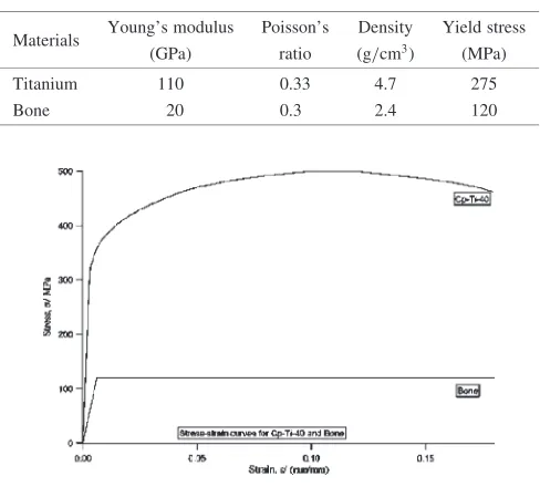
In bone-ingrowth cases, a moderate value of the Young’s modulus of cortical bone is chosen.1)Due to lack of reliable data on the hardening plasticity behavior of bone, here we assume elastic-perfectly-plastic behavior with the yield stress defined as 120 MPa. All the parameters and stress-strain curves are shown in Table 2 and Fig. 1.
Table 1 Nominal Composition-mass% for Allvac 40, Ti CP-2
(UNS-R50400).
C Fe H N O Ti
[image:2.595.305.549.552.772.2]0.10 max 0.30 max 0.015 max 0.03 max 0.25 max rem
Table 2 Material parameters of titanium and bone.
Materials Young’s modulus Poisson’s Density Yield stress
(GPa) ratio (g/cm3) (MPa)
Titanium 110 0.33 4.7 275
Bone 20 0.3 2.4 120
To examine the influence of pore morphology on mechan-ical properties, several idealized geometries are examined. In all cases, the volume fraction of the titanium matrix is 56% while the volume fraction of pores is 44%. The baseline configuration consists of 25 periodically distributed circular pores and is referred to as the ‘standard geometry’. Results are then assembled for a number of permutations of morphology, all based on the standard geometry.
. ‘ellipse’: elliptical instead of round pores.
. ‘move in center’: position of central pore is perturbed. . ‘change in center’: size of central pore is perturbed. . ‘random position’: randomly distributed pores of
uni-form size.
. ‘random size’: rando mization of pore sizes, but spatially uniform distribution.
. ‘random combination’: randomly distributed pores of random sizes.
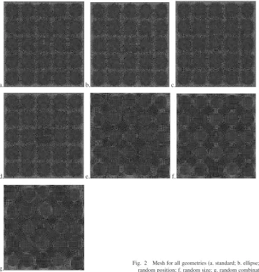
The geometric configurations can be seen in Fig. 2. All models are then examined as either fully porous, fully filled with bone,partially filled with bone. ‘Fully porous’ means that all pores are empty, where to avoid numerical difficulties a modulus of 110 7GPa is defined to the empty pores.
‘Fully filled with bone’ simulates bone growth into all pores, and the mechanical parameters of bone are given for all pores. ‘Partially filled with bone’ simulates partial bone ingrowth into pores near the boundary while other pores are
left empty.
For all models, the boundary conditions are defined as follows: the bottom boundary fixed in the y-direction; the left boundary is fixed in the x-direction; the right boundary with coupling constraint in the x-direction which ensures that all points of the right boundary have the same displacement in x-direction. All the pores are tied with the titanium matrix so that all points of the interfaces between pores and titanium matrix will have same displacement in all directions. A displacement boundary condition of up to 1% macroscopic strain is applied on the upper boundary. Use of displacement condition allows easy control of the calculation steps which is useful to gain the stress/strain information at onset of the first local plastic deformation.
To obtain the mesh, the boundaries and the interfaces between pores and titanium matrix are seeded by number which guarantees that both the seed and the nodes of the elements along boundaries and interfaces between bone and titanium matrix will locate at the same position. Linear quadrilateral elements are chosen to mesh all the area. This type of element shows good precision and achieves reliable results for both elastic and plastic regime, and still does the calculation with reasonable time and memory space. All geometries and mesh are created with ABAQUS/CAE. Then the general purpose ABAQUS finite element code is used to solve all models.
a. b. c.
d. e. f.
[image:3.595.116.485.396.783.2]3. Results and Discussion
The foaming kinetics are shown for a Ti foam created by superplastic expansion of Ar bubbles. The microstructure and mechanical properties of this foam with 50 vol% porosity are then presented. Finite element simulations were run to explore the impact of pore morphology and bone filling on the local and macroscopic mechanical properties of the Ti foam. The results are presented below, first examining the effect of the pore configurations on modulus and local and global yield properties. Subsequently, the effect of full and partial bone ingrowth is examined.
3.1 Materials processing
[image:4.595.67.272.399.590.2]Metallographic examination of the hot-pressed specimen revealed that the initial porosity was about 0.06%, and the pore size was about 12mm. Upon exposure to elevated temperature, these pores expand by creep expansion of the matrix. As demonstrated in Refs. 25–27) for similar speci-mens, thermal cycling triggers superplastic deformation in the titanium matrix, resulting in foaming rates and maximum porosity much higher than if foamed at a the maximum cycle temperature.
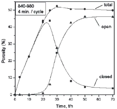
Figure 3 shows a foaming curve, where the first two points were from the first two samples, and the last six from the third. Total porosity increases near linearly with time until a
value of 50%, which is achieved after 25 hours of foaming. Porosity remains closed to the surface until it reaches a value of 44% after 20 h of foaming. Porosity then opens to the surface over a period of ca. 30 hours. The maximal porosity value of 53% is achieved after 30 h, at which point half the porosity is open. Foaming cessation is thus a combination of loss of argon in pores connected to the specimen surface and decreased pressure in those still closed, as also reported in Refs. 26, 27). The small decrease in porosity from 53 to 50% may be due to experimental error and/or to sintering of small pores, after the gas they contained had escaped.
Figure 4 is a metallographic section of the sample after 70 h. of foaming, with a near-complete open porosity of 50%. Pores are very large (about 150–300mm), within the size
range of 50–400mm recommended for bone cell
in-growth.3,30,31)The pore large size and jagged shape are the result of internal pore merging during the foaming; when porosity is closed, their shape are much more spherical.26) Very thin pore walls exist, illustrating the very large strains achievable under superplastic conditions.
Figure 5 shows the compressive stress-strain curve for the foam shown in Fig. 4, with most of its 50% porosity open (Fig. 3). Upon initial loading, the apparent Young’s modulus is about 5 GPa, and the first deviation from linearity occurs at a stress of 90 MPa. A value of 12 GPa is found for the Young’s modulus, as measured on unloading and subsequent reloading upon reaching a stress of 140 MPa, at a total strain of 4%. The low value of the initial apparent Young’s modulus is probably the result of microplasticity occurring on initial
Fig. 3 Ti foam porosity (total, open and closed) as a function of time under thermal cycling conditions (4 minute cycles between 840 and 980C).
Fig. 4 Optical micrograph of Ti foam with 50% porosity, showing large, interconnected pores with ragged surfaces. Thin pore walls are also visible.
0 10 20 30 40 50
Ti 50% porosity
0 10 20 30 40 50
0 100 200 300 400 500
600 Ti
50% porosity
Stress,
σ
/MPa
Strain, ε/%
0.0 1.0 2.0 3.0 4.0
0 20 40 60 80 100 120 140
Stress,
σ/
MPa
5 GPa
12 GPa
Strain, ε/%
[image:4.595.324.527.428.582.2] [image:4.595.129.472.629.769.2]loading, and so the value of 90 MPa is probably significantly higher than the true yield stress (see later examples of the local onset of yield in the simulations). Note that such values for modulus and strength are closely matched to those of bone, which is ideal for the optimal goal of a non-stress-shielding bone implant.
For comparison, FEM calculations for a Ti foam with 44% closed porosity (see results in the next section) predict values of 63 MPa for the yield stress and 30 GPa for the modulus. The correlation between the p redictions and experimental data is reasonable given the lower porosity of the numerical simulation and the rough and elongated pore morphology for the experimental sample. The rough pore protrusions are non-structural material segments decrease apparent porosity, while elongated pores are well known to decrease effective modulus.
3.2 Effect of morphology
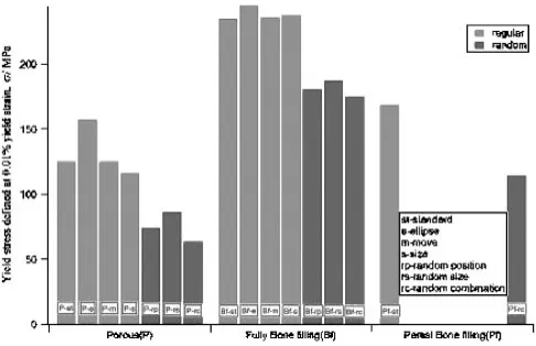
The small perturbations of the shape, size and position of pores have little influence on the Young’s modulus, as seen in Fig. 6. The modulus for the case with elliptical pores is larger than all other porous cases due to the alignment of the ellipses in the loading direction. One striking feature is that the ‘standard’, ‘ellipse’, ‘move in center’ and ‘change in center’ models all have similar Young’s modulus, while the ‘random’ models including ‘random position’, ‘random size’ and ‘random combination’ all have significantly smaller Young’s modulus. This result is also pronounced in the results for the yield stress shown in Fig. 8. The yield stress is defined as the stress that achieves 0.1% yield strain, shown in Fig. 7. Again, small perturbations of a single pore within a periodic arrangement have little effect, while randomization of the locations and sizes of the pores significantly decrease the macroscopic yield point. Since the foaming process produces microstructures which are not arranged on a precise periodic lattice, this result implies that predictive models need to account for the random nature of the pores to avoid overpredicting macroscopic material properties. It is worth noting that the most common methods of modulus prediction for foams do not account for random microstructures. The effects of bone filling on modulus and yield threshold are discussed in the next section.
To examine the effect of morphology on the onset of local plastic deformation in the neighborhood of the pores, a
plastic flag was employed. Figure 9 shows the influence of the size and position on the plastic deformation, where red indicates stress beyond the plastic limit, blue indicates elastic regime. Note that the yield strain concentrates in the neck region in between neighboring pores and that the plasticity is more localized in the cases with a perturbed pore even though the macroscopic yield properties are quite similar the standard case.
Stress concentrations can be visualized in contour plots of the stress magnitudes in the porous geometries as in Fig. 10. The stress tends to concentrate in the neck areas between pores. Compared to the standard case, changes in the position and size of the central pore cause locally smaller ligaments between pores in which stresses are noticeably higher at the same applied strain level. There is less stress concentration in the case of elliptical pores than in standard geometry because the inter-pore ligaments are thicker transverse to the loading direction than those in standard model. For the non-standard geometries, shear banding often appears, centering in the inclusion that has the largest plastic deformation as seen in Fig. 11.
3.3 Effect of bone filled pores
Since the material microstructure is best represented by the random combination geometric model, here we examine the influence of bone ingrowth for this case and the standard model only. First, consider the macroscopic stress-strain
Fig. 6 Young’s modulus of all models.
[image:5.595.48.292.62.231.2]Fig. 8 Yield stress for all models, defined by 0.1% strain offset as shown in Fig. 7.
[image:5.595.315.538.73.216.2] [image:5.595.305.548.261.418.2]curves for filled and unfilled samples shown in Fig. 12. Note that the simulations are run to a relatively low strain level for two reasons: first is to avoid numerical difficulties associated
with pore collapse and compaction; and secondly, the application of the material as a bone implant motivates consideration of the initial and local yield properties far below the onset of compaction. Results in Fig. 12 illustrate that for the same geometry, bone ingrowth causes a larger Young’s modulus and yield stress. This is also seen in the results in Figs. 6 and 8. Thus, bone ingrowth will delay the
a.
c.
b.
d.
Fig. 9 Onset of local plastic deformation shown at macroscopic strain level 0.2% for several cases (a, b, c) and at macroscopic strain level 0.14% for random geometry (d). Red indicates local plasticity threshold achieved, while blue areas are in elastic regime. (a. standard, b. move in center, c. change in center; d. random combination).
a b
c d
e
[image:6.595.47.292.71.329.2]a b
[image:6.595.275.548.73.655.2]Fig. 11 Shear banding appears centered in inclusions with largest plastic deformation for fully bone filling. (a. random position, b. change in center).
Fig. 10 Stress contour plots for several porous geometries and 0.3% macroscopic strain level. (a. standard, b. ellipse, c. move in center, d. change in center, e. contour color scale; (Unit for stress is GPa)).
a
c
b
d
[image:6.595.47.285.406.683.2]onset of plastic deformation for a porous material, in spite of the relat ively low modulus of bone compared to titanium.
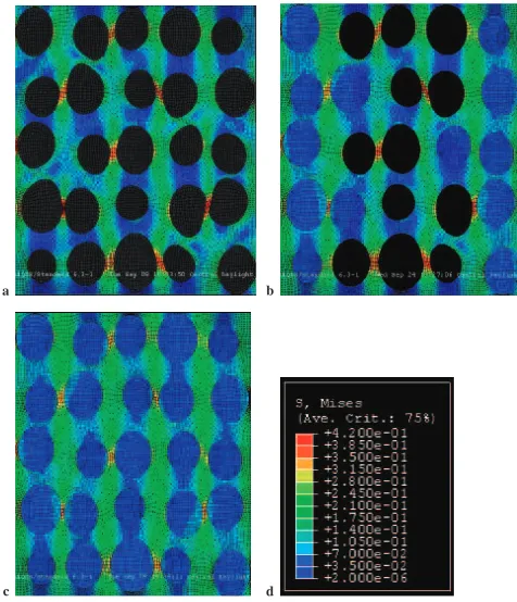
One of the most dramatic influences of bone ingrowth is the change in local material response. This can be illustrated in several ways. First results for the stress contour plots for porous, partial filled and fully filled are shown in Fig. 13. When the positions of the pores are distributed randomly, the shapes of some pores are changed under large deformation as shown in Fig. 13a, and the large stresses in confined ligaments increase substantially above the applied macro-scopic load (red areas). The localized deformation is reduced in the case where the sample is fully filled by bone, as are the local stress concentrations (Fig. 13c). Partial bone ingrowth protects the outer pores, but the inner still porous material is still subjected to elevated stress levels. This result indicates that fully open porosity to allow full bone ingrowth would be ideal in the eventual application.
In addition to stress contour plots, the magnitude of stress and strain at the onset of the first local plastic deformation in the material is a useful quantitative metric. In all cases, the first local plastic deformation in the titanium matrix appears significantly before the strain and stress reach the overall yield strain and yield stress. The influence of bone ingrowth can be seen in Fig. 14, where complete bone ingrowth increases the maxiumum stress that can be applied without any local plastic deformation by more than a factor of two. Compa ring these values to Fig. 12, it is clear that the first local plastic event occurs at stresses less than half the macroscopic yield value in all cases.
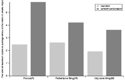
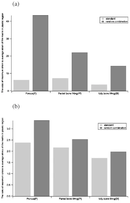
A stress concentration factor can be obtained by consid-ering the ratio of the maximum stress to the average applied stress. In the elastic region (no localized plasticity), this ratio is shown in Fig. 15, where it is seen that bone ingrowth can decrease the stress concentration factor by close to a factor of two in the random geometry. Bone ingrowth has significantly less influence on the stress concentrations for the periodically arranged pores. Once plastic deformation is reached, the ratio of maximum strain to average strain and the ratio of maximum stress to average stress of matrix differ from one another and from those shown in Fig. 15. The strain values and ratios are naturally much larger than the stresses due to the limits on stress during plastic deformation. Magnitudes
can be seen in Fig. 16.
It can be seen in the above results that the bone ingrowth significantly improves the material properties of the porous titanium, in particular for materials with random pore size and locations where localized plasticity and large stress concentrations can occur easily. Although the increase of the Young’s modulus through the bone ingrowth is not ideal for the orthopaedic implant application, the moduli still remain much lower than the Young’s modulus of solid Titanium. Thus the material with bone ingrowth will still reduce the negative effects of stress shielding that exist in current solid Titanium implants. For example, the Young’s modulus of the fully bone filled model with random combination geometry (52 GPa) is much lower than that of solid Titanium (110 GPa), although it is larger than that of the corresponding unfilled porous model (31 GPa). Compared to porous and partial filling, full bone ingrowth will improve both overall plastic properties and local mechanical properties that are very important for orthopedic implants. Considering all aspects, bone ingrowth will improve the overall material response of the orthopedic implants.
4. Conclusion
[image:7.595.57.282.71.225.2]In this paper, we have demonstrated development of a porous Ti foam material of mid-ranged porosity, with applications toward bone replacement engineering. Exper-imental results demonstrate a foam of 50% porosity with dramatically reduced modulus and yield strength, which can
[image:7.595.320.531.72.209.2]Fig. 12 Macroscopic stress-strain curve for selected models from finite e lement simulations. Symbols indicate the stress level at the onset of local plasticity in the matrix.
Fig. 14 Macroscopic stress when first local plastic deformation appears.
[image:7.595.322.530.245.379.2]provide advantages for bone ingrowth and reduced stress-shielding. Finite element simulations were performed on idealized geometries which demonstrated that both pore morphology and bone ingrowth have significant influence on the mechanical properties of the titanium foam. Slight changes of the shape, size and position of pores have little influence on the Young’s modulus and overall yield stress. However, randomization of size and spatial distribution, similar to that seen in experimental samples, causes Young’s modulus and overall yield stress to decrease significantly. Also the stress concentration of the random geometries is much greater than regular geometries. Another revealing result is that the localized plasticity occurs well within the nominally ‘‘linear’’ region, at less than half the macroscopic yield threshold.
Perhaps the most important feature is the impact of bone ingrowth. For the same geometry, bone filling remarkably improves the mechanical properties of the implant. With bone ingrowth, both Young’s modulus and yield stress increase, stress concentrations decrease and plastic deforma-tion is delayed. These results indicate that design of porous foams with open porosity to allow full bone ingrowth are desirable to increase the mechanical viability of the material. The analysis used here can als o be employed to specify the stress and strain values in the initial bone ingrowth (and the full bone ingrowth) as a function of pore morphology, pore locations, applied loading. Ongoing work is beginning to
relate these parameters to bone cell growth in experiments for improved material design.
Acknowledgments
The authors gratefully acknowledge support of this work by the National Science Foundation under grant number DMR-0108342.
REFERENCES
1) M. Long and H. J. Rack: Biomaterials19(1998) 1621–1639. 2) K. D. Riew and J. M. Rhee: Clinical Orthopaedics and Related
Research,394(2002) 47–54.
3) J. D. Bobyn, R. M. Pilliar, H. U. Cameron and G. C. Weatherly: Clinical Orthopaedics and Related Research150(1980) 263–270. 4) T. Mori and K. Tanaka: Acta Metall.21(1973) 571–574.
5) J. Aboudi: Mechanics of Composite Materials-A Unified Microme-chanical Approach, Elsevier, 1991.
6) L. Gibson and M. Ashby:Cellular Solids: structure and Properties (Cambridge University Press, 1997).
7) T. Christman, A. Needleman and S. Suresh: Acta Metall.37(1989) 3029–3050.
8) J. Llorca, A. Needleman and S. Suresh: Acta Metall. Et Mater.39
(1991) 2317–2335.
9) H. Shen and C. J. Lissenden: Mater. Sci. and Eng.A338(2002) 271– 281.
10) M. Ostoja-Starzewski, P. Y. Sheng and I. Jasiuk: Engineering Fracture Mechanics58(1997) 581–606.
11) S. Moorthy and S. Ghosh: Inter. J. Numerical Methods Eng.39(1996) 2363–2398.
12) S. L. Thelen:Titanium Foam for Use in Bone Implants: Microstructure Effects on effective Properties and Local States, in Mechanical Engineering. June 2000, Northwestern University: Evanston, Illinois. 13) S. L. Thelen, F. Barthelat and C. L. Brinson: Journal of Biomedical
Materials Research, (2003).
14) Y. Benveniste: Mech. Matls.6(1987) 147–157.
15) E. D. Spoerke, N. G. Murray, H. Li, C. L. Brinson, D. C. Dunand and S. I. Stupp: Nature Materials, (manuscript in preparation, 2003). 16) N. Taylor, D. C. Dunand and A. Mortensen: Acta Metall. Mater.41
(1993) 955–965.
17) I. H. Oh, N. Nomura and S. Hanada: Mater. Trans.43(2002) 443–446. 18) I. H. Oh, N. Nomura, N. Masahashi and S. Hanada: Scr. Mater.49
(2003) 1197–1202.
19) M. Bram, C. Stiller, H. P. Buchkremer, D. Stover and H. Baur: Adv. Eng. Mater.2(2000) 196–199.
20) C. E. Wen, M. Mabuchi, Y. Yamada, K. Shimojima, Y. Chino and T. Asahina: Scr. Mater.45(2001) 1147–1153.
21) M. W. Kearns, P. A. Blenkinsop, A. C. Barber and T. W. Farthing: Metals and Materials3(1987) 85–88.
22) D. T. Queheillalt, B. W. Choi, D. S. Schwartz and H. N. G. Wadley: Metall. Mater. Trans. A31(2000) 261–273.
23) D. M. Elzey and H. N. G. Wadley: Metall. Mater. Trans. A30(1999) 2689–2699.
24) D. M. Elzey and H. N. G. Wadley: Acta Mater.49(2001) 849–859. 25) N. G. Davis, J. Teisen, C. Schuh and D. C. Dunand: J. Mater. Res.16
(2001) 1508–1519.
26) N. G. D. Murray and D. C. Dunand: Compos. Sci. Technology 63
(2003) 2311–2316.
27) N. G. D. Murray, C. A. Schuh and D. C. Dunand: Scr. Mater.49(2003) 879–883.
28) A. International:Atlas of stress-strain curves. 2nd ed. (Materials Park, OH: ASM International, 2002).
29) D. B. Freels, S. Kilpatrick, E. S. Gordon and W. G. Ward: Clinical Orthopaedics and Related Research394(2002) 315–322.
30) J. Klawitter and S. Hulbert: J. Biomed. Mater. Res.6(1971) 161–229. 31) S. Simske, R. Ayers and T. Bateman: Mater. Sci. Forum250(1997)
151–182.
(a)
[image:8.595.64.274.73.401.2](b)