Steam Oxidation Studies on 50Ni-50Cr HVOF Coatings on 9Cr-1Mo Steel:
Change in Structure and Morphology across the Coating/Substrate Interface
*Thiyagarajan Sundararajan, Seiji Kuroda and Fujio Abe
National Institute for Materials Science, Tsukuba 305-0047, Japan
Steam oxidation resistance of 50Ni-50Cr coatings sprayed by a high velocity oxyfuel process on modified 9Cr-1Mo steel substrate was evaluated in the temperature range of 873–1023 K. The present study focuses on the microstructural changes during the oxidation tests. The coated samples showed the formation of chromium carbide at the coating/substrate interface during the steam oxidation. The magnitude of the chromium carbide formation was increased with increase in the temperature and the duration. Microstructural examination of the etched cross sections showed that beneath the chromium carbide layer the substrate microstructure transformed from tempered martensite to higher grain-width ferrite microstructure. The carbon depletion in this region resulted into longer ferrite grain formation. Micro hardness studies showed that at the coating/substrate interface the micro hardness values increased with increasing the test temperature and the duration. The substrate layer just beneath the coating showed the decreased hardness values compared to the core substrate region.
(Received November 7, 2003; Accepted February 13, 2004)
Keywords: steam oxidation, 9 chromium - 1 molybdenum steel, nickel-chromium coating, high velocity oxy fuel spray, microstructure
1. Introduction
Thermal spray coatings are considered as a promising technique for improving the oxidation and hot corrosion resistances of the materials exposed to high temperature
environments.1,2)Thermal spray process has several
advan-tages for application to large-scale structures such as its capability to do onsite modification, small heat input to the substrate and high deposition rate. These positive features stimulated us to find out the suitability of the thermal spray process for the steam oxidation resistance of USC boilers, which will be used in the thermal power plants. The present power plants operate at the steam temperature of 823 K and the modified 9Cr-1Mo steel shows the satisfactory
perform-ance at this temperatures.3)In the near future, the operating
temperature is intended to increase to 923 K, which facilitates the increased plant efficiency with reduction in the emission gas. Our group has undertaken a project to explore the suitability of thermal spray processes for this application and
the results have been documented elsewhere.4–8) HVOF
coating of 50Ni-50Cr showed the excellent steam oxidation
resistance in the tested duration of 1000 hours.5) The
formation of chromium oxide on the top surface of the coating protected the material against steam oxidation. However, formation of chromium carbide was noticed at the coating/substrate interface for most of the specimens. This may have an adverse effect on the integrity of the coating in the long duration. The present study aims to study
the kinetics of chromium carbide formation with different temperature and duration. Also, the changes in structure and morphology of the adjacent layers due to chromium carbide formation have been studied. In particular, the diffusion of the carbon to form these carbides has been examined with the microstructure evaluation and micro hardness studies of the steel substrate.
2. Materials and Method
The 9Cr-1Mo type ferritic steel was used as a substrate
specimen with following dimensions. 1 cm2area with 4 mm
thick specimens coated with 50Ni-50Cr powder (Manufac-turer: Praxair). Chemical composition of the substrate and powder are represented in Table 1. Thermal spray coatings were deposited out using a HVOF spray process (JP 5000, Praxair, TAFA), which utilize the supersonic jet generated by the combustion of kerosene-oxygen mixture. The process parameters used for coating are given in Table 2.
[image:1.595.44.549.700.742.2]Prior to the coating process, the specimens were sand blasted using alumina powder for better adhesion of the sprayed coatings to the substrate. Six passes were adopted including the two pre-heating passes for pre-heating the substrate. Thickness of the coating obtained was about 60mm. The coated specimens were supplied to X-ray diffraction (XRD) and scanning electron microscope (SEM) investigations before placing them into the steam oxidation chambers. Steam oxidation tests were carried out at different
Table 1 Chemical composition of substrate and coating powder (mass%).
Material C P S Si Mn Cr Ni Mo Cu V Al N Nb Fe
9Cr-1Mo 0.10 0.005 0.001 0.24 0.44 8.74 0.04 0.94 0.01 0.21 0.014 0.058 0.076 bal 50Ni-50Cr 0.05 — — 0.7 0.2 50 bal — — — — — — 2.8
*This Paper was Presented at the Autumn Meeting of the Japan Institute of
temperatures viz., 873, 923, 973 and 1023 K. The procedure followed for the steam oxidation process was described
elsewhere.4)The sample pieces were taken out after different
durations namely 36, 360 and 3600 kilo seconds (ks) of steam oxidation test. The surfaces of oxidized specimens were analyzed by XRD to identify the new phases formed during steam oxidation in comparison with the as-coated conditions. Backscattered electron image (BSE) and electron probe micro analysis (EPMA) studies were carried out on the cross sections to reveal their change in morphology and the elemental distribution of the coating after the steam oxida-tion.
The substrate microstructure was examined from the cross sections. For the microstructure examinations the polished specimens were swabbed in the vilellas reagent (100 mL ethyl alcohol + 5 mL HCl + 4 g picric acid) for 20 seconds, subsequently cleaned with the de-ionized water. Micro hardness studies were carried out on the cross sections of the steam oxidized specimens in comparison with the as-coated conditions. The load applied for each indentation was 0.050 kg.
3. Results and Discussion
3.1 As-coated morphology
Figure 1 shows the XRD spectra of 50Ni-50Cr powder and its coating made by the HVOF process. The powder pattern exhibited three major peaks responsible for Ni-Cr (111), (200) and (220) indicating that the powder exists in a single fcc phase. In the case of the coating, it also showed an
identical spectrum pattern as the powder. According to the Ni-Cr phase diagram, 50Ni-50Cr consists of two phases, Ni rich fcc phase and Cr rich bcc phase. The presence of single fcc phase indicated that the powder and the coatings are in a supersaturated meta stable state and the HVOF coating of 50Ni-50Cr retained the phase of the powder. However, peak broadening was noticed for coated specimen compared to the XRD pattern for the powder material. This is attributed to the lattice distortion occurred during spray process.
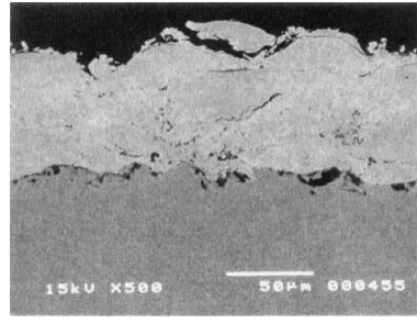
The BSE image cross section for the 50Ni-50Cr coating on modified 9Cr-1Mo steel substrate is represented in Fig. 2. The HVOF coating process yielded the thickness of around
60mm and the coating appears to be free from through
porosity.
3.2 Steam oxidation 3.2.1 EPMA studies
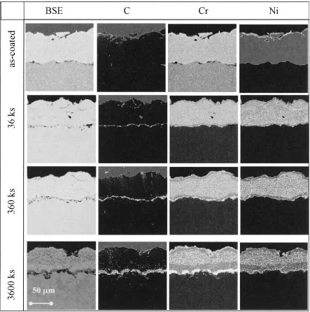
Figure 3 shows the EPMA elemental mapping for the 50Ni-50Cr coated specimens steam oxidized at 1023 K for three different durations. At 36 ks (10 h) of oxidation, the C elemental mapping showed a thin layer of high C concen-tration at the interface, which was absent in the respective as-coated condition. The Cr elemental mapping also shows the enrichment of Cr at the similar position with carbon. These results inferred that during the steam oxidation, the 50Ni-50Cr coating on 9Cr-1Mo steel substrate yielded the formation of chromium carbide at the interface. With further increase in the test duration to 360 and 3600 ks (100 and 1000 hours), the BSE image showed the visible dark gray layer at the interface. The black colored portion observed in the BSE image coincide with the enrichments of C and Cr in their respective elemental mappings. This indicated the formation of chromium carbide at the interface. The thickness of the chromium carbide formed at the interface increased with the increase in the test duration. Apart from the chromium carbide formation, the coating did not undergo any other drastic changes such as diffusion of the coating elements to
the substrate. In our earlier studies,4)the 80Ni-20Cr coating
showed significant diffusion of Ni from the coating to the steel substrate. In the present system the absence of such diffusion may be attributed to the formation of chromium carbide at the interface, which might have retarded the diffusion.
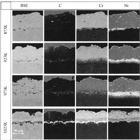
[image:2.595.329.519.72.219.2]Figure 4 shows the EPMA elemental mapping for the
Table 2 Spray parameters used for HVOF spray process. Fuel (kerosene) flow rate 0.00632 dm3/s
Oxygen flow 14.37 dm3/s
Barrel length 0.102 m Torch traverse speed 0.700 m/s Spray distance 0.380 m Powder feed gas Nitrogen (N2)
Powder size 20–53mm
Manufacturer Praxair
Fig. 1 XRD spectra for 50Ni-50Cr powder and its coating produced by HVOF process.
[image:2.595.47.291.84.195.2] [image:2.595.49.288.593.757.2]50Ni-50Cr coated specimen steam oxidized for 3600 ks at different test temperatures. The specimen steam oxidized at 873 K showed the absence of C and Cr enrichment at the coating/substrate interface. This infers that steam oxidation at 873 K did not form chromium carbide at the coating/ substrate interface till the test duration of 3600 ks. The specimens steam oxidized at 923 K and 973 K showed the enrichment of C at the coating/substrate interface, where the enrichment is scattered and non-continuous. Considering the Ni elemental mapping, the specimen 873 K/3600 ks showed a small amount of inward diffusion. At 923 and 973 K the diffusion of Ni proceeded to the further distance at the substrate compared to the 873 K. On the other hand, in the case of 1023 K-tested condition, the Ni map showed a least diffusion to the substrate materials compared to all other tested temperatures. This inferred the following points: The diffusion rate of Ni is increased with increase in the test temperatures. Similarly, the chromium carbide precipitates at the coating/substrate interface becomes thicker and
contin-uous with increase in temperature and duration. Once the chromium carbide forms a continuous layer, the diffusion of Ni to the substrate will be restricted. This can be noticed in the specimens tested at 1023 K, where the continuous chromium carbide layer formed even at 36 ks of test durations and absence of Ni inward diffusion to the steel substrate.
3.2.2 Microstructural examination
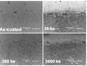
Figure 5 show the microstructures of the specimens cross-sections, steam oxidized at 1023 K for different durations in comparison with the as-coated condition. The steel substrate of the as-coated specimen showed the tempered martensite/ ferrite microstructure, which is as expected for normalized modified 9Cr-1Mo steel. In steam oxidation of the coated specimen at 1023 K/360 ks, the substrate region adjacent to the coating showed the bigger grain size compared to core substrate microstructure. The microstructure consists of grains with bigger grain formed in the Cr-Mo steels are typically known as ferrite microstructure. The formation of
[image:3.595.77.520.71.518.2]the bigger grain structure is arise from the recovery of excess dislocations and the sub grain structures. With increasing the test duration the region with bigger grain width also expanded towards the inner portion of the steel substrate. At 3600 ks tested condition, the bigger grain region increased
to more than 50mm. The transformation of tempered
martensite/normalized banite structures to the ferritic struc-ture has been documented in the welded strucstruc-tures of
dissimilar Cr-Mo steel.9,10) Post weld heat treatment of
dissimilar weld between the steel with different Cr concen-tration or the Cr-Mo steel and the stainless steel often results in the formation of a carbon depleted soft ferrite zone in the
low Cr side and carbides precipitated in the high Cr side.9,10)
This phenomenon was attributed to the migration of carbon from the low Cr side as a consequence of the difference in the activities of carbon present in the materials with difference in the Cr concentration. This can be explained by the following equation considering the binary alloy (Fe-Cr) system.
ac¼Nc½expðNA"cAþNB"cBÞ
Where,acis the activity of the carbon;NA,NBand theNCare
the number of constituent atoms A, B and the carbon present
in the alloy, respectively;"c
Aand"cBrepresent the Wagner
interaction parameter for the constituent element A and B.10)
For the chromium, the Wagner interaction parameter is negative and the higher the Cr concentration the lower the activity of the carbon.
In our present system, the coating consists of Ni-Cr system and the substrate is Fe-Cr system. The carbon activity for Ni system is considered to be higher than the Fe systems if the
concentration of binary element (Cr) is the same.11)However,
the coating Ni-Cr system has a very high Cr concentration (50 mass%) than the substrate Fe-Cr system (9 mass%). Since
the Wagner interaction parameter ("cCr) is negative, the
higher Cr concentration in the coating might have lowered the activity of the carbon to a level even below that of the
[image:4.595.68.527.68.528.2]substrate. This could be the driving force behind the carbon migration from the steel substrate to the adjacent coating region and formation of the chromium carbide at the coating/ substrate interface. Consequently, the substrate region ad-jacent to the coating become depleted with carbon concen-tration and hence transformed to the ferrite microstructure.
The stepwise mechanism of breaking the smaller grains, carbon migration and the higher width ferrite grain formation
are discussed elsewhere.10)
Figure 6 shows the microstructure of cross sections for the 50Ni-50Cr coated modified 9Cr-1Mo steel specimens steam oxidized for 3600 ks at different temperatures. At 823 K the
Fig. 5 Effect of substrate microstructure adjacent to the coating with steam oxidizing duration.
[image:5.595.114.486.69.353.2] [image:5.595.113.484.393.674.2]specimen did not show any bigger-grain width microstructure in the substrate adjacent to the coating. Instead of that a small portion of the substrate adjacent to the coating (around
510mm thickness) showed a smooth surface without any
distinct microstructure. This region coincided with the Ni diffusion zone of the steel substrate observed in the EPMA studies (Fig. 4). From the above results it is concluded that at 873 K, the carbon migration did not occur from the substrate to the coating whereas the Ni diffusion occurred to the
substrate from the coating. In our earlier studies4) the
diffusion of Ni occurred from the 80Ni-20Cr coatings to the same modified 9Cr-1Mo steel substrate. The Ni rich zone also showed the similar smooth surface and it was identified
as austenite by micro XRD studies.8)This suggested that the
smooth surface obtained in the 873 K/3600 ks specimen might have arisen from the formation of Ni-rich austenite structure. Increasing the temperature from the 873 K to 923 K and 973 K, the ferrite zone is not very clear compared to the 1023 K-tested condition. This may be due to the following reason; though the carbon migration might have occurred in the area adjacent to the coating region for both 923 and 973 K, the Ni diffusion also occurred from the coating to the substrate. This resulted in the complicated microstructures for both the specimens.
3.2.3 Micro hardness studies
Figure 7 shows the micro hardness studies carried out on the cross section of the coating and the near substrate regions for as-coated and steam oxidized specimens at 1023 K. The as-coated specimen showed the uniform hardness values of
about 460 HVacross the coating structure. The substrate near
the coating interface showed a little higher value compared to the core substrate. The reason for the increased hardness value at substrate near the interface might be the work hardening produced by the sandblasting the substrate prior to the coating process. The specimens steam-oxidized at 1023 K for 36 ks showed the variation in the hardness values across the coating structure. In particular, at the interface, the specimen showed the higher hardness values. The increased hardness value at the interface was attributed to the formation
of chromium carbide at this region, which was identified by EPMA studies. With further increase in the test duration from 36 ks to 360 and 3600 ks, the hardness values showed the similar trend of variation in the coating region and the hardness values at the interface increased further. At 1023 K/ 3600 ks condition the value obtained at the interface was
around 700 HV. This is much higher than the average coating
hardness value of 460 HV. However, the coating near the
interface showed lower micro hardness values compared to the average hardness values of the coating. This might arise from the depletion of Cr in this zone, which was consumed to form chromium carbide. In the substrate, the region adjacent to the coating interface showed lower values compared to the core substrate. However, the difference is very small compared to the core substrate. In the as-coated specimen, it showed the higher hardness values in this region compared to the steam oxidized conditions. The decreased hardness values at this region were attributed to the change in the microstructure from the tempered martensite to the ferrite along with carbon depletion.
The hardness measurements were extended to the speci-mens steam oxidized at different temperatures for 3600 ks and the results are represented in Fig. 8. The specimen steam oxidized at 873 K showed little variation in hardness across the coating structure, and also, at the interface, it did not show any increase in the hardness. This has a good agreement with the EPMA studies, in which it showed the absence of chromium carbide formation at the coating/substrate inter-face. Similar trend was observed for the specimens steam oxidized at 923 K. On the other hand, the specimens steam oxidized at 973 and 1023 K showed higher hardness values at the interface. In the substrate, decreased hardness values were observed in the region just beneath the interface compared to the core substrate, but the difference appears to be very small. The hardness studies revealed that though the carbon migration occurred from the near substrate region to the coating/substrate interface to form the chromium carbide, the carbon depleted zones showed the hardness values very close to the core substrate.
Fig. 7 Micro hardness measurements on 50Ni-50Cr coatings steam oxidized at 1023 K for different duration.
Fig. 8 Micro hardness measurement on 50Ni-50Cr coatings steam oxi-dized for 3600 ks at different temperatures.
[image:6.595.68.270.564.758.2] [image:6.595.325.527.564.758.2]The results obtained in this study by analyzing the coated specimens before and after steam oxidation are summarized as follows: In the as-coated condition, the coating has the uniform concentration of Cr across the coating and beneath that the steel substrate possesses the tempered martensite structure with uniform grain size. After the steam oxidation, both coating and the zone underneath the substrate undergo a few changes. On the top of the coating, chromium is enriched as a chromium oxide leaving the chromium depleted zone in the underlying layer. At the coating/substrate interface, for 1023 K-tested conditions, chromium is enriched to form a continuous layer of chromium carbide, which resulted in the absence of Ni diffusion to the substrate. The substrate region adjacent to the coating turns into the low-hardness carbon-depleted zone. This causes the substrate microstructure to transform from the tempered martensite to ferrite with bigger grains. Below 1023 K the chromium carbide does not form a continuous layer, which allows the Ni in the coating to diffuse into the substrate resulting in a more complicated microstructure.
4. Conclusion
The 50Ni-50Cr coatings formed by HVOF spraying for protection of modified 9Cr-Mo steel from steam oxidation at the USC condition showed the formation of chromium carbide at the interface during steam oxidation. The thickness of carbide formation is increased with increase in the temperature and the duration. A continuous carbide layer was formed at temperature of 1023 K, whereas, carbide precipitates appeared in a dispersed manner below 973 K. When the carbide formed a continuous layer, the Ni diffusion from the coating to the substrate was essentially blocked, whereas, when the carbide precipitates were dispersed and non-continuous, Ni diffused from the coating to the substrate.
The carbon required to form the chromium carbide migrated from the substrate adjacent to the coating. The carbon depletion in the segment of substrate resulted in the ferrite microstructure with lower hardness.
Acknowledgements
The authors are very much thankful to Mr. K. Nishida for his help in EPMA analysis. The first author (T.S) thanks Dr. S. K. Albert, IGCAR, India for the fruitful discussion during his stay at NIMS.
REFERENCES
1) W. Kaysser: Surface Engineering,17(2001) 305–311.
2) C. Cheng, G. H. Meier, R. A. Perkins and W. T. Bekker: inMaterials for coal gasification(ed. R. W. Bekkeret al.), (Metals Park, OH, ASM International, 1988) p 159–169.
3) R. Viswanathan and W. Bekker: J. Mater. Engg. Perfom.10(2001) 81– 95.
4) T. Sundararajan, S. Kuroda, T. Itagaki and F. Abe: ISIJ Int.43(2003) 95–103.
5) T. Sundararajan, S. Kuroda, T. Itagaki and F. Abe: ISIJ Int.43(2003) 104–111.
6) T. Sundararajan, S. Kuroda, T. Itagaki and F. Abe: in Thermal Spray 2003: Advancing the science & Applying the Technology, (Ed) C. Moreau and B. Marple, (ASM International, Materials Park, Ohio, USA, 2003) pp. 495–502.
7) T. Sundararajan, S. Kuroda, K. Nishida, T. Itagaki and F. Abe: ISIJ Int.
44(2004) 139.
8) T. Sundararajan, S. Kuroda and F. Abe: Collected Abstracts of the 2003 Autumn Meeting of the Japan Institute of Metals, pp 366 (in Japanese). 9) O. K. Chopra, K. Natesan and T. F. Kassner: J. Nucl. Mater.96(1981)
269–284.
10) C. Sudha, A. L. E. Terrance, S. K. Albert and M. Vijayalashmi: J. Nucl. Mater.302(2002) 193–205.
11) A. M. Katsnelson, V. Y. Dashevskly and V. I. Kashin: Steel Research