Agent-Based Synthesis of Distributed Controllers
for Discrete Manufacturing Systems
Ernesto López-Mellado
CINVESTAV Unidad Guadalajara, Zapopan, Mexico. Email: [email protected]
Received February 4th, 2011; revised February 23rd, 2011; accepted February 25th, 2011.
ABSTRACT
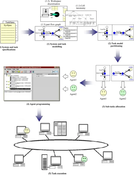
A method for designing real-time distributed controllers of discrete manufacturing systems is presented. The approach held is agent based; the controller strategy is distributed into several interacting agents that operate each one on a part of the manufacturing process; these agents may be distributed into several interconnected processors. The proposed method consists of a modelling methodology and software development framework that provides a generic agent archi- tecture and communication facilities supporting the interaction among agents.
Keywords: Agent-Based Software Design, Distributed Knowledge Based Controllers, Discrete Manufacturing Systems
1. Introduction
Nowadays discrete manufacturing systems are large and complex systems that integrate several kinds of devices of miscellaneous nature and behaviour, namely robots, con- veyors, machines, sensors, etc. Additionally, the produc- tion requirements are often changed; these facts impose to the system components to be versatile, and to the coor-dination system or controller to be highly flexible.
The core of a control system is complex software, which determines at last, the flexibility and the perform-ance of the automated system. This control software pro-vides several functions: tasks execution, monitoring, de-cision making, and planning; it is generally distributed into a four layer hierarchy [1]; in this scheme the control function is decomposed into four levels in which the re-sponse time is shortest in the lower levels.
The lowest level includes the local controllers of the physical devices in the cell (robots, conveyors, machines, sensors, etc. The task coordination level or cell level manages and supervises the activities of the local control- lers involved in a cell by the generation of pertinent com- mands according to events issued from the local control level. The task planner generates the strategy of the con-troller for the cells according to the specifications from the production planning level.
Due to the complexity of the tasks, especially which performed at the cell level, the synthesis of the controller is a difficult job often addressed through planning
tech-niques. One of the problems found in the synthesis real- time controllers is that the representation of the qualitative controller often includes a large amount of knowledge whose processing is time consuming.
This work deals with the task coordinator level. The functions of this control level can be decomposed mainly in a) the sequencing of operations to accomplish the as-sembly task in a normal functioning regime, and b) the handling of exceptions representing operation failures [2]. In this paper the case of normal execution is addressed.
The design and implementation of tasks controllers of complex manufacturing systems has been addressed by using several approaches. The object oriented approach has been held for modelling [3], simulation [4-6], and con- trol [7] of manufacturing systems. The agent based ap-proach [8] has been adopted to address some problems in manufacturing systems [9]; DeLoach [10] proposes a mo- delling language for describing the diverse kinds of agents, and defines a methodology (MaSE) for the formal synthe- sis of agent systems; in [11] Bussmann focuses on deci-sion making issues during the planning stage, and in [12] he addresses the task programming issue proposing a syn- thesis method that leads to concurrent centralised control software; in [13] Ouelhadj proposed a dynamic control ar- chitecture for manufacturing systems organised into cells, but the programming of the agents is not reported.
executed; Section 3 presents the proposed method for the design of distributed control software: first the decompo-sition of the task model is described, then agent based solution to the synthesis of distributed software is out-lined.
2. Controller Modelling
This section presents the methodology that helps to ob-tain systematically the contents of the knowledge bases from a model of the manufacturing/assembly system; this model, close to that presented in [7], includes the system description and the tasks specification. The aim of this stage is to obtain in a structured way the system function- ing and production requirements.
The description consists in a component classification of the manufacturing process, and a structuring of the sys- tem workspace.
The component classification leads to a taxonomy of the system components organised as a hierarchy including capabilities and features of each component, and the total quantity of devices. The hierarchy is useful to program the necessary classes in the control software. Figure 2 shows an example of components hierarchy.
2.1. System Description
The structuring of the system workspace consist of a defi- nition of relevant physical emplacements where operations are performed on the work pieces or parts; rather than spa- ce partition into regions, the structuring is a discrete assi- gnment of positions. The key element for structuring the workspace is the notion of site, which is defined as the place where parts can be temporary held or stored in a sta- ble position (a table, a magazine, a robot gripper, ...) [2].
The sites may be single or composed (macro-site); sin- gle sites held one part or subassembly; composed sites have two or more emplacements which manage the infor- mation attached to a set of sites closely located and func-tionally equivalents. The sites that are associated to effec- tors are named active sites; otherwise they are called pas- sive sites. A site contains information about the work zone were it is emplaced that can be used as mutual exclusion resource (for robot collision avoidance, for example).
into a site. For example, Figure 3 describes the operations
pick and place performed by a robot (R1); three sites are involved: two passive sites (CONV2 and TAB1), and an active site (GRIP1) associated to the robot gripper. The definition of FPG is given below:
Definition. A flow of parts graph is the tuple F = (G, SITES, OPER, , , ), where
G is a connected directed graph G = (V, A), where —V is a finite set of vertex,
—A V V is a set of edges or arcs.
SITES = {site1, ···, siten} is a finite set of site names,
which are not input or output sites.
= {sitein1, ···, siteinp, siteout1, ···, siteoutq} is a fini-
te set of site names labelling sites where the parts entry or leave the FMS.
: V SITES {} is a labelling function that assigns name sites to the vertex of G.
: A OPER is a labelling function that assigns operations names to the arcs of G.
2.2.2. Sequencing the Operations
The dispatching rules are antecedent-consequent rules that state the conditions in which an operation must be exe-cuted; they are obtained directly from the FPG, and the number of rules is the same than the number of arcs in the FPG. The antecedent part is composed by conditions that involve mainly sensory conditions and tests (contents, part posture, …) on the sites related by the operation; other conditions may involve tests on sites located upstream the FPG. The consequent part includes the request of execu-tion of the associated operaexecu-tion and the updating of the involved sites.
2.3. A Modelling Example
For illustrating purposes we include an example regarding a simple assembly system; it will be addressed through the rest of the paper.
2.3.1. System and Task Description
1) The system: Consider the assembly cell sketched in
Figure 2. Taxonomy of the assembly cell.
CONV2 GRIP1 TAB1
[image:4.595.59.302.88.439.2]Pick.R1 Place.R1
Figure 3. Flow of parts graph.
B1
B2
B3 R1
R2
ST A1
A2 C1
Figure 4. Assembly cell layout.
the storing table has four positions. The parts to be as-sembled arrive through the conveyor B1; two kinds of as- sembled products the leave the cell through B2 and B3. In the front of R1, an optical sensor C1 detects the arrival of parts; over this zone a camera of a location-recogni- tion system is emplaced.
2) The task: Eight types of parts (A, B, C, D, E, F, G, and H) constitute the input flow in B1; they arrive at ran- dom order. R1 gets the parts and builds assemblies (stacks) on A1 (with the parts A, B, C, and D) or A2 (with the parts E, F, G, and H) according to a predefined order for each product. The detection of parts in C1 stops B1; the identity of the parts is determined by the vision system when they arrive at the position C1. R1 gets part only if it can be as- sembled or temporary stored in STi. Otherwise the part is left in B1. R2 gets completed assemblies from A1 or A2 and places them on B2 and B3 respectively.
2.3.2. System and Task Modelling
1) System taxonomy. The components of the assembly system are classed from a functional point of view: sen- sors, effectors, etc. This classification is useful to struc-
ture the factual knowledge of the assembly system: task state, component capabilities and relationships, etc. Fig-ure 2 shows the hierarchy concerning the assembly sys-tem of the example; the isys-tems in the lowest level of the hierarchy can be object instances of the upper concept (class).
2) Workspace modelling. In the example the following sites are defined: CONV1, CONV2 and CONV3 are the sites associated to the place where the parts stops in front of the robot; GRIP1 and GRIP2 are associated to the grip- pers of R1 and R2 respectively. The storing table has four sites: STi (i = 1, ···, 4); they can be managed by the macro site ST. The sites associated to assembly tables are ASSB1 and ASSB2.
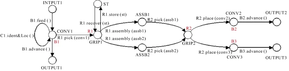
3) Flow of parts. The FPG shown in Figure 5 describes the flow of parts required in the assembly task; the sites defined in the model are related by the operations whose outcome is, mainly, the transferring the parts between the sites. Operations may only modify the properties of the part into a site; as an example notice that the operation Ident-Loc does not transfer the part to another site but it changes the attributes of the unknown part.
Operations may also put parts into the flow model or drawn out parts (or products) from the model. The FPG for this example is defined as follows:
F = (G, SITES, OPER, , ) where G = (V, A) with V = {v0, v1, v2, v3, v4, v5, v6, v7, v8, v9, v10, v11}
A = {(v0, v1), (v1, v2), (v1, v1), (v1, v3), (v3, v4), (v4, v3),
(v3, v5), (v3, v6), (v5, v7), (v6, v7), (v7, v8), (v7, v9), (v8, v10),
(v8, v11)}
SITES = {conv1, conv2, conv3, grip1, grip2, assb1, assb2, st1}
= {input1, output1, output2, output3}
Figure 5. Flow of parts graphs for the assembly cell.
(conv2), R2.place2(conv3), B2.advance(), B3.advance(), C1.ident&Loc()}
= {(v0, input1), (v1, conv1), (v2, output1), (v3, grip1),
(v4, st1), (v5, assb1), (v6, assb2), (v7, grip2), (v8, conv2),
(v9, conv3), (v10, output2), (v11, output3)}
= { ((v0, v1), B1.feed()), ((v1, v2), B1.advance()), ((v1,
v3), R1.pick(conv1)), ((v3, v4), R1.store(st)), ((v4, v3),
R1.retreive(st)), ((v3, v5), R1.assembly(assb1)), ((v3, v6),
R1.assembly(assb2)), ((v5, v7), R2.pick(assb1),), ((v6, v7),
R2.pick(assb2)), ((v7, v8), R2.place(conv2)), ((v7, v9),
R2.place(conv3)), ((v8, v10), B2.advance()), ((v8, v11),
B3.advance()), ((v1,v1), C1.ident&Loc())}
3. Distributed Software Design
This section deals with the design of the distributed soft- ware that implements the task controller of a manufactur- ing system. First the modularisation of the task model is presented, and then the resulting partition is taken for im- plementing the agents [14].
3.1. Task Model Partition
The task model must be decomposed into subtasks in such manner that every subtask may be assigned to an agent; this decomposition is achieved by a partition of the FPG. Several strategies for obtaining sub-graphs from the FPG may be adopted according to the number of processors, the geographical distribution on the components, or the simi- larity of the sub-graphs.
In this work the strategy held for decomposing the gra- ph is creating the maximal number of sub-graphs; each sub-graph must involve one active site. This approach al- lows defining agents capable to control one effector. A three-step algorithm is described below.
Algorithm. Partitioning the task model.
1) Identify active and passive sites. Let Act SITES, the set of active sites and Pass SITES the set of passive sites.
2) Sub-model creation. For every sAct, create a sub- graph gk including s and its predecessors and successors.
In gk it is included an active site and several passive sites.
SG = {g1, g2, ···, gr} is the set of sub-models.
3) Simplification of sub-models. The operations asso-ciated to the arcs of a graph gk must be executed by the
effectors or sensors associated to the active site of gk. Thus
the arcs labelled with other operations must be withdrawn from gk; consequently isolated vertex must be eliminated too.
The sites belonging to two or more gk are called
inter-face sites; they are in the boundary of the graph and they must be carefully managed because they are considered as shared resources.
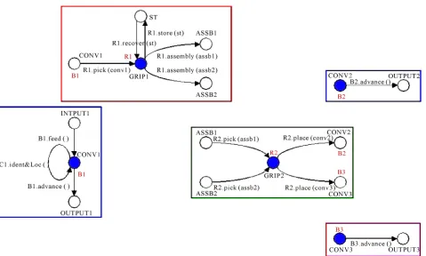
Example. Consider the FPG of Figure 5; defining Act = {conv1, conv2, conv3, grip1, grip2}, and Pas = {asb1, assb2, st}, the decomposition procedure yields the sub- graphs depicted in Figure 6; so SG = {g1, g2, g3, g4, g5}.
3.2. Task Programming Framework
Once the task model is decomposed, each sub-model is used for defining an agent. Since every sub-model invol- ves an actuator, it must be controlled by the corresponding agent avoiding situations in which two or more agents handle the same effector. The knowledge base of every agent corresponds to the set of rules associated to the arcs of the pertaining subtask.
The developed platform supports the programming of the agents that implement the subtasks of the system; this platform is based on JADE V1.2 (Java Agent Develop-ment framework) [15], which meets the standards of FIPA [16].
3.2.1. Requirements
Agent requirements. Each agent has a unique name
manages the corresponding subtask; it initialises and updates the contents of its sites and macro-sites. exchanges messages with other agents; it interprets
the message and perform the requests such as pro-vide information about the contents of a site or about
the execution of an operation.
Figure 6. Graph decomposition.
manages the associated devices (effectors and sen-sors involved in the subtask).
Sites requirements. Each site or macro-site has a unique name.
provides facilities for managing its state, i.e. the ini-tialising and updating of the associated attributes such as contents, position, sensor values, trace of the operations performed on it, etc.
provides facilities for managing special features, such as flags for mutual exclusion, the agent names that share it, or the assembly patterns if it is a site for assembly.
Devices requirements. For every device (effector or sensor) in the system, one must create an interface mod-ule that allows consulting the device state and handling the messages representing actions requests or responses. Every module has a unique name.
3.2.2. Definition of Classes
Component architecture. The implemented components are integrated into a package organised in four sub-pack- ages; it is shown in Figure 7. The sub-package MApack- age.sites contains the classes Site and Part, MApack-age.macrosites contains the class Macrosite and the class- es related with the access of sites contained in the macro- site. Three kinds of sites are considered: interface sites
(shared by two or more sub-tasks), internal sites, and re-
mote sites (non shared but belonging to other sub-tasks).
Figure 8 shows a detail of the above packages.
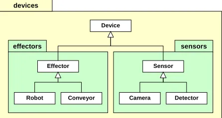
The sub-package MApackage.devices contains the class
Device and other sub-packages. MApackage.devices. effectors and MApackage.devices.sensors contain sub-classes illustrated in Figure 9. This organisation is strongly suggested by the taxonomy of the manufacturing system obtained during the modelling stage.
[image:6.595.309.535.534.702.2]Agent class. The class AgentBase is an abstract class that specialises the class Agent from JADE. This class em-
Figure 8. Relationships among sub-packages.
sensors effectors
devices
Device
Effector Sensor
Camera
Robot Conveyor Detector
Figure 9. Devices sub-package.
beds the behaviour of a generic agent that manages all the activities related to a subtask. Every agent must be pro-grammed by extending AgentBase, declaring the knowl-edge of the corresponding subtask, and instancing the ex- tended subclass. The generic agent provides the facilities for the management of sites and the handling of messages related with the manufacturing task and messages for in- teracting with other agents; interaction among agents is performed through four kinds of messages regarding in-formation requests and sending about sites, and request/ confirmation on the use of sites shared by two or more agents.
Agent programming. The programming of each agent is done based in the information obtained from the cor-responding subtask graph.
3.2.3. Component Identification
The first step for programming an agent is to identify the rules, the sites, the actions, and devices regarding the sub- task. For every site in the graph one must declare which agent shares this site, and define if it is a remote site. If a site is used for assembly declare the assembly pattern to follow during the execution of the task. When an in terface site is associated to sensor, only one agent must manage
Operation Ident-Loc
Description
If during the feeding a part is detected, the con-veyor 1 stops and the part is identified. The sen- sor value is reset.
Related sites Conv1
Related devices Conveyor1, Vision system, Detector.
Pre-conditions
Conv1 is empty, the state of conveyor is FEED-ING, the presence sensor is ON, and the subtask state is INITIAL.
Actions Stop Conveyor1. Identify and locate the part with
the vision system. Reset sensor.
Post-conditions
[image:7.595.307.536.83.257.2]Conv1 holds a part, the state of Conveyor1 is STOP, the vision system is IDLE, and the sensor is OFF. The state of the task is HOLDINGPART.
Figure 10. Frame for a rule description.
such sensor.
3.2.4. Building the Rule Base
The rules define the strategy of the controller. Every agent has a small set of rules corresponding to the arcs of the sub-graph. Before the writing of the rules it is convenient to enumerate all the information regarding each rule. This may be systematised by the filling of frames, such as shown in Figure 10 for the operation Ident-Loc of the sub-task 1.
The Java coded rules for the agent coordinating the sub- task 3 is given below.
// implementing rules for the agent named
// ManufacturingAgent3
void rules()
{
// declaring reference to site for place //the
part
Site destinationPart = null;
// GRIP2.TAKE1: Grip2 takes the assembled //part
from ASSB3
if(assb3.getSite(0).isAssembled() &&
grip2.isEmpty() &&
conv2.isEmpty() && destinationPart==null)
{
grip2.setContent(assb3.getContent(0));
assb3.removeContent(0);
sendUpdateMessages(grip2);
sendUpdateMessages(assb3);
//
destinationPart = conv2;
}
// GRIP2.TAKE2: Grip2 takes the assembled part
// from ASSB4
if(assb4.getSite(0).isAssembled()&&
grip2.isEmpty() &&
[image:7.595.61.284.286.405.2]Part.isEmpty() && destinationPart!=null)
{
destination-
Part.setContent(grip2.getContent();
grip2.removeContent();
sendUpdateMessages(destinationPart);
sendUpdateMessages(grip2);
destinationPart = null;
}
}
3.3. Implementation Issues
This method has been demonstrated through the software implementation of several case studies. The software has been written in Java using the JADE framework for sup-porting the agent definition and task interaction.
The distributed software has been tested on several per- sonal computers interconnected through a local area net- work; every agent was assigned to single PC.
For executing the controller, first the JADE framework is initiated in a computer where an agent may be executed, and then the rest of the agents are started in their compu- ters.
For every agent the interaction with a device has been simulated through a visual interface on screen; during a test, users simulate the devices response to commands sent by the controller through the keyboard.
4. Conclusions
In this work a method to develop distributed software for manufacturing control systems has been presented. One important issue of the proposed method is the modelling stage; the specifications are transformed into graphical models that contribute to reduce the problems due to am-biguities and incompleteness. The partitioned task model leads to obtain systematically the knowledge of every agent in the control software, allowing modifying easily the strategies of the subtasks; this feature is useful when task reprogramming is needed.
The programming methodology takes advantage of the JADE framework facilities, which permit to the defined agents to be executed into different kinds of platforms.
Discrete Event Systems, Vol. 77, No. 1, January 1989, pp. 195-209.
[2] E. López and R. Alami, “A Failure Recovery Scheme for Assembly Workcells,” IEEE International Conference on
Robotics and Automation, Cincinnati, May 1990, pp
702-707.
[3] E. Arjona-Suárez and E. López-Mellado, “A Computer Language for the Modelling of Flexible Manufacturing Systems,” Proceedings of the 13th IASTED International Symposium on Robotics and Manufacturing Santa Bar-bara, California, November 1990, pp. 183-187.
[4] C. R. Glassey and S. Adiga, “Conceptual Design of a Software Object Library for Simulation of Semiconductor Manufacturing Systems,” Journal of Object Oriented Programing, Vol. 2, No. 4, 1989, pp. 39-43.
[5] M. Bakalem, G. Habchi and A. Courtois, “PPS: An Inte-grated Object Oriented Approach for Modelling and Simulation of Manufacturing Systems,” IEEE Interna-tional Conference on Systems, Man and Cybernetics. Texas, 2-5 October 1994, pp. 2184-2189.
[6] G. Ramzi, M. Bakalem and G. Habchi, “An Object Model for Simulation of Manufacturing Systems,” IEEE Inter-national Conference on Systems, Man and Cybernetics, Vancouver, 22-25 October 1995, pp. 137-142.
[7] E. López and E. Medrano, “Object-Based Design of FMS Controllers,” Proceedings of IASTED International Con-ference on Robotics and Manufacturing, Cancun, May 1997. pp. 342-345.
[8] N. R. Jennings, K. Sycara and M. Wooldridge, “A Road-map of Agent Research and Development,” International Journal of Autonomous Agents and Multi-Agent Systems, Vol. 1, No. 1, 1998, pp. 7-38.
doi:10.1023/A:1010090405266
[9] W. Shen and D. H. Norrie, “Agent-Based Systems for Intelligent Manufacturing: A State-of-the-Art Survey,”
Knowledge and Information Systems,Vol. 1, No. 2, 1999, pp. 129-156.
[10] S. A. DeLoach, “Multiagent Systems Engineering: A Me- thodology and Language for Designing Agent Systems,”
Agent-Oriented Information Systems’99, Seattle, 1 May 1998, pp. 45-57.
[11] S. Bussmann, H. Baumgärtel and M. Klosterberg, “Multi- Agent Coordination of Material Flow in a Car Plant,”
[12] S. Bussmann, “Agent-Oriented Programming of Manu- facturing Control Tasks,” Proceedings of the 3rd Interna- tional Conference on Multi-Agent Systems, Paris, 1998, pp. 57-63.
[13] D. Ouelhadj, C. Hanachi and B. Bouzouia, “Multi-Agent System for Dynamic Scheduling and Control in Manu-facturing Cells,” Proceedings of the IEEE International Conference on Robotics and Automation, Leuven, 16-20 May 1998, pp. 2128-2133.
[14] J. G. Morales-Montelongo, “Agent-Based Distributed Co-
ordination of Manufacturing Systems,” MSC Thesis, Cinvestav Unidad Guadalajara, Mexico, November 2002.
[15] F. Bellifemine, A. Poggi and G. Rimassa, “JADE—A FIPA—Compliant Agent Framework,” Proceedings of International Conference on Practical Applications of Intelligent Agents and Multi-Agent Technology, London, April 1999, pp. 97-108.