CALCULATION OF TENSION FORCE
OF BELT CONVEYOR
Ismet Ibishi1
Department of Mining Engineering, University of Prishtina Mitrovice, Republic of Kosovo
ismetibishi609@hotmail.com Ahmet Latifi2
Department of Mechanical Engineering, University of Prishtina Mitrovice, Republic of Kosovo
ahmetnlatifi@hotmail.com Gzim Ibishi3
Department of Mining Engineering, University of Prishtina Mitrovice, Republic of Kosovo
Gzim-Ibishi@hotmail.com Kadri Sejdiu4
Department of Mechanical Engineering, University of Prishtina Mitrovice, Republic of Kosovo
kadrimsejdiu@live.com Melihate Shala-Galica5
Department of Mechanical Engineering, University of Prishtina Mitrovice, Republic of Kosovo
Bekim Latifi6
Department of Mechanical Engineering, University of Prishtina Mitrovice, Republic of Kosovo
bekimlatifi123@hotmail.com
Abstract:
In this paper is done the explanation on tension fashion of the belt conveyor which is employed in Kosovo Energy Corporation – KEK, for coal transportation to provide electric power plant. The aim of the paper enables to recognize tension forces not to pass with deformation of belt so that this problem will damage the working process. Work principle is based on initial tension and tension during working process. The fact is known that the tension starts from the carriage on the way to tension mechanization, so forces on the rope passing through pulley there has to dominate the friction coefficient. All this process is related to economy of transportation mechanism.
Key words: belt conveyor, tension force, carriage, friction coefficient, mechanism, pulley.
1. Introduction
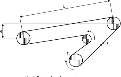
Belt conveyors can be used for hoisting rock up surface slopes, drifts for inclinations not greater than 18°.
Raghvendra, Arvind, Pratesh [2012],a typical conveyor installation has the following principle components
such as; belt which carries the material, idler which support the carrying, pulleys which support and move the belt and control its tension as well as change directions, and drive which transmits the motive power to one or more pulleys to move the belt and its carrying load. Ramlu [1996], as belt conveyors consists of several components, their careful selection and design have decisive influence on the capital and operating costs and
hence the economy of conveyor transportation as a whole. Lech, Robert, Jędrzej [2011] stated that a good belt
conveyor design is based on
Fig 1 Principle scheme of conveyor
Todd, Larry, Andrew [2002], Baldin, Furlanetto, Turco [1982] Belt conveyors have shown the ability to
transport materials that vary from large, heavy, sharp-edged lumps to fine particles; from wet, sticky slurry to dry, dusty powders; from foundry sand to potato chips; and from tree-length logs to wood chips. Of all the material handling systems, belt conveyors typically operate with the lowest transport cost per ton, the lowest maintenance cost per ton, the lowest power cost per ton, and the lowest labor cost per ton. From the illustrating above we gain;
(1) (2)
Whereas the tension force [Ft] that secure the normal work during the movement of belt conveyor is;
(3)
So that if we have . Then;
2 (4)
Substituting the force [F2] in function of [Fp] the tension force is;
(5) Where are;
µ - Coefficient of sliding friction between the belt and pulley
- Angle of contact or angle of wrap of the belt around the pulley in radians
Table 1 Friction coefficient
µ - Coefficient of sliding friction between the belt and pulley
Surface of drum Steel Rubber layer Ceramic layer
Dry surface 0.35-0.4 0.4-0.45 0.4-0.45
Wet clean surface 0.1 0.35 0.35-0.4
Wet lubricated surface 0.05-0.1 0.25-0.3 0.35
For our study problem we have [µ = 0.35] and [ = 2000] in table 1 shown friction coefficient [µ] so whether we
substitute in equation 5 we get tension force 0.83332 . Values of tension force [Ft] are given in table 3
Table 2 Values of
Contact
Angle
Friction coefficients of drive pulley
0.10 0.15 0.20 0.25 0.30 0.35 0.40 0.45 0.50 0.55 0.60 170 180 190 2.895 2.709 2.543 1.784 1.661 1.552 1.234 1.144 1.063 0.909 0.838 0.775 0.697 0.638 0.587 0.548 0.499 0.456 0.439 0.398 0.361 0.357 0.321 0.290 0.293 0.262 0.235 0.243 0.216 0.192 0.203 0.179 0.158 200 210 220 2.394 2.259 2.136 1.453 1.364 1.284 0.990 0.925 0.866 0.718 0.667 0.621 0.541 0.499 0.462 0.418 0.384 0.353 0.329 0.300 0.274 0.262 0.238 0.216 0.212 0.190 0.172 0.172 0.154 0.138 0.140 0.125 0.111 230 240 250 2.024 1.922 1.828 1.211 1.144 1.082 0.812 0.763 0.718 0.579 0.541 0.506 0.428 0.398 0.370 0.325 0.300 0.277 0.251 0.230 0.212 0.197 0.179 0.163 0.155 0.140 0.127 0.124 0.111 0.100 0.099 0.088 0.079 360 370 380 1.144 1.102 1.063 0.638 0.612 0.587 0.398 0.379 0.361 0.262 0.248 0.235 0.179 0.168 0.158 0.125 0.116 0.109 0.088 0.082 0.076 0.063 0.058 0.053 0.045 0.041 0.038 0.033 0.030 0.027 0.024 0.021 0.019 390 400 410 1.025 0.990 0.957 0.563 0.541 0.519 0.345 0.329 0.314 0.223 0.212 0.201 0.149 0.140 0.132 0.102 0.095 0.089 0.070 0.065 0.061 0.049 0.045 0.042 0.034 0.031 0.029 0.024 0.022 0.020 0.017 0.015 0.014 430 450 0.894 0.838 0.480 0.445 0.287 0.262 0.181 0.163 0.118 0.105 0.078 0.068 0.052 0.045 0.035 0.030 0.024 0.020 0.016 0.013 0.011 0.009 Table 3 Values of tension force [Ft]
Floor Conveyor
V-1 Z-1 ZTU-1 KTU-1 KTU-2 ITU-1 ITU-2 STU-1 STU-2
15386.72 8 69479.7 9 36939.7 33243.66 8 23593.43 9 249653. 8 106408.0 6 18116.24 3 46132.52 9 Main Conveyor
GTU-1 XIII-a XIII GTU-3 GTU-4 XII XIII-a XIV XV
71241.32 6
6980.62 2037.52 5
42395.7 81134.92 72444.9
2
39318.92 89977.35 83434.13 9
2. Materials and Methods
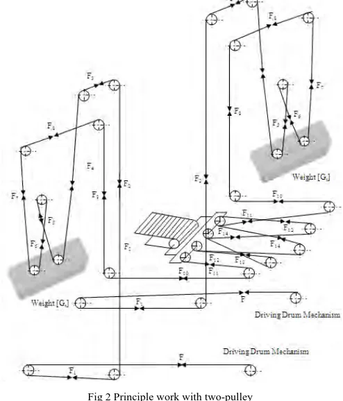
According to principle scheme of mechanism for tension of belt which is shown in figure 2, is consisted by driving drum, weight, infinite rope, carriage for tension, moveable pulley, and unmovable pulley. The working principle is done into two steps, first one is initial tension and the second step is tension during work. During initial tension the weight is placed on the floor whereas belt conveyor is loose. When the mechanism of driving drum activates, the rope is wrapped on drum whereas the tension carriage starts gradually to move, when the tension force in tension carriage is based on weight, then the weight start to lift up. If the weight is lift up until to an unexpected height, then the driving mechanism is determined and the brakes will activate so that the drum cannot move further. After the initial tension is done, then the conveyor may start working. During the working process the loads may change on belt conveyor and also the tension force will change which is necessary to secure normal work. The balance of these loads makes it possible to lift up and down different weights according to how loads vary respectively how the length of the belt varies.
3. Results and Discussion
3.1Calculation of loads for tension with two- pulley
From the principle scheme 2, for the initial tension we have;
, , (6)
Whether we substitute by [Gt] we have;
(7)
In the same fashion for tension force [Ft] we have;
2 (8)
If we substitute previous equation by [Gt];
From the principle scheme 2, for tension during the working we have;
, , , (10)
If we substitute [Fz] we have;
(11) If we substitute [F], in the same fashion for weight we get;
(12)
For [ = 0.95] we have 0.3014153 . Number of disks is; / . Results of the calculation of
loads for tension with two pulleys are presented in table 4;
Fig 2 Principle work with two-pulley
Table 4 Results of tension with two pulleys
Conveyor ZTU-I KTU-I KTU-2 STU-I STU-2
Fp(N) 44328.35 35898.04 28318.5 21739.84 57759.96
Initial
tension 0.4648
20603.817 18543.04 13160.2 10510.09 26847.92
/ 3.4339 3.09 2.1933 1.68418 4.4747
Tension during work
0.2511 11133.907 10019.89 7111.35 5460.373 14507.51
/ 1.8556 1.6699 1.1852 0.691 2.4179
No of rings 5 5 5 5 7
Avg. no of rings
/2 2.6447 2.3799 1.689 1.297 3.4459
3.2Calculation of loads for tension with four-pulley
According to principle scheme of tension we have tension force [Ft] and weight [G].
2 (13)
(14) Initial tension has to dominate friction resistances of pulley from driving drum up to carriage tension. The
Fig 3 Principle work with four-pulley
From the principle scheme in figure 3, the initial tension is;
, , (15)
If [Gt] is substituted we have;
(16)
The force in the drum is given;
(17)
If we substitute in [Gt];
(18)
For [ = 0.95] we have 1.242448 . If we substitute [Fsh] into [Gt] we have 1.035 , its
weight makes safety work without slipping in the beginning. The number of rings is given;
(19) We understand that the tension during the work starts from the carriage tension towards to tension mechanism. During this time forces which come up on the rope while they pass through pulleys have to dominate the friction
coefficient. This friction factor we consider through utilization coefficient [ = 0.95]. From the principle scheme
in figure 3 we gain formulations of tension during working;
, , , , (20)
From the above expressions we gain;
(22) Whereas the weight is given as;
(23) If we substitute [F] we gain;
(24)
For [ = 0.95] we have 0.5195 . If we substitute [Ft] into [Gt] we have 0.43295
This is the minimal force of tension during the work, when the forces are in balance. If the loads are smaller then it cannot secure the normal work of driving mechanism. The weights are composed of rings, and their total
weight is 600 . The number of rings is given;
Results of the calculation of loads for tension with four pulleys are presented in table 5; Table 5 Results of tension with four pulleys
ITU-1 ITU-2 GTU-1 XII XIII-a XIII GTU-3 XIV XV GTU-1
2958 9. 37 1279 81. 72 8549 0. 84 8693 3. 79 4781 2. 9 6702 1. 32 5087 5. 12 1079 75. 57 1001 70. 57 9736 2. 37 In itial Tigh ten in g 0.4648 3062 4. 997 1321 60. 99 8848 3. 019 8997 6. 472 4883 4. 3 6936 7. 06 5265 5. 74 1115 74. 4 1036 76. 53 1007 70. 05 5. 104 22. 026 14. 747 14. 99 8. 13 11. 56 8. 775 18. 62 17. 279 16. 795 Ti ght eni n g du ri ng wo rk 0.4648 1280 9. 238 5527 7. 745 3700 8. 884 3673 3. 637 2042 5. 477 2901 3. 529 2202 3. 83 4674 2. 494 4336 3. 838 4214 8. 169 2.
13 9.2 6.2
6.
27 3.4
4. 83 3. 67 7. 79 7.
227 7.03
Nu
mb
er of 10 10 11 12 11 13 11 11 12 12
Nu mbe r of measures of 3. 617 15. 62 10. 457 10. 63 5. 765 5. 198 6. 222 13. 205 12. 253 11. 9
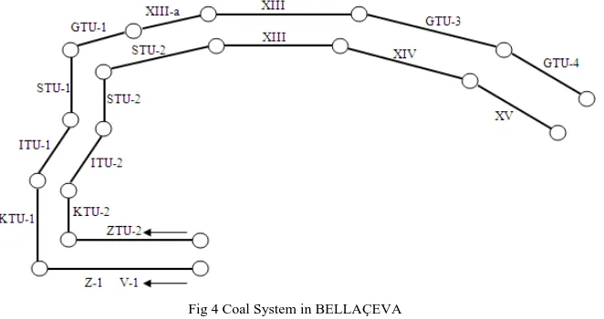
Fig 4 Coal System in BELLAÇEVA
3. Conclusion
In this paper are realized calculations of weights of loads in rubber belt of conveyor which at the same time are done according to tension force of belt that relates with the force of rope of pulleys. We have done the calculations of forces during the tension of system with tow and four pulleys, these calculations have its technical and economical importance because is know the duration of belt and tension rope and enable to know the time of replacement of belts and their maintenance.
References
[1] Baldin, A., Furlanetto, L., Turco, F. (1982). Priručnik za održavanje industrijskih postrojenja, OMO Beograd
[2] Lech G., Robert K., Jędrzej B. (2011). Tests of belt conveyor resistance to motion; Eksploatacja i Niezawodność - Maintenance and Reliability, 3: 17-25.
[3] Raghvendra, S.G., Arvind, Y., Pratesh, J. (2012). Failure analysis of belt conveyor system in a thermal power plant, IJATER, 2(3) pp.204-210.
[4] R. Todd Swinderman., Larry J. Goldbeck., Andrew D. Marti. (2002). Foundations 3: The Practical Resource for Total Dust & Material Control, Neponset, Illinois, USA.
![Table 3 Values of tension force [Ft]](https://thumb-us.123doks.com/thumbv2/123dok_us/9665738.1494435/3.595.65.544.83.444/table-values-of-tension-force-ft.webp)