IJSRSET1841114 | Received : 10 January 2018 | Accepted : 27 January 2018 | January-February-2018 [(4) 1 : 496-500 ]
© 2018 IJSRSET | Volume 4 | Issue 1 | Print ISSN: 2395-1990 | Online ISSN : 2394-4099 Themed Section : Engineering and Technology
496
Experimental Analysis for Optimizing Parameter Heating
System
M. Sabaskar1, Dr. K. Karthick2
1Post Graduates, Department of Mechanical Engineering, King College of Technology, Namakkal, Tamil Nadu,
India
2AssociateProfessor, Department of Mechanical Engineering, King College of Technology, Nallur, Namakkal,
Tamil Nadu, India
ABSTRACT
This suggest a better replacement of cold mass fraction which defines the ratio between the mass of air moving out through the cold exit to the actual mass of air entering the vortex tube through the inlet. Sustainable manufacturing Innovations elements are Remanufacture Redesign, Recover, Recycle, Reuse, Reduce. It has a good thermal response that restructures it with a low temperature. The properties of materials are particular to the exact composition of the metal and the way it was processed. The optimizing the parameters of vortex tube for increasing the cooling temperature. These optimized vortex tube could produce maximum hot gas temperature of 391 K at 12–15% hot gas fraction and a minimum cold gas temperature of 267 K at about 60% cold gas fraction. CFD - a computational technology that enables one to study the dynamics of things that flow. CFD is concerned with numerical solution of differential equations governing transport of mass, momentum and energy in moving fluid. Cold air machining outperforms mist coolants and substantially increases tool life and feed rates on dry machining operations. The effective cooling from a Cold Air Gun can eliminate heat-related parts growth while improving parts tolerance and Surface finish quality Commercial vortex tubes are designed for industrial applications to produce a temperature drop of about 26.6 °C (48 °F). With no moving parts, no electricity, and no Freon, a vortex tube can produce refrigeration up to 6,000 BTU (6,300 kJ) using only filtered compressed air at 100 PSI (689 kPa). A control valve in the hot air exhaust adjusts temperatures, flows and refrigeration over a wide range.
Keywords: Computational Fluid Dynamics Analysis, Navier – Stokes Equations, SIMPLE, SIMPLE-C, SIMPLER, QUICK and PISO.
I.
INTRODUCTION
The vortex tube (also called Ranquehilsch vortex tube) is a simple mechanical device which splits a compressed gas streaminto cold and hot streams without any chemical reactions or external energy supply. Vortex tubes have advantages compared to other refrigerating or heating devices, being simple, having no moving parts, using no electricity or chemicals and having long operation time. They need only compressed gas to operate. Their critical
excellent review of the studies existing in the literature can be found in a recent study and a more recent study. The mystery topic for the vortex tubes is the energy separation effect. Although the vortex tubes have been known for decades, the mechanism producing temperature separation phenomenon asa gas or vapor passes through a vortex tube hasn’t been fully understood yet accordingtoRanque, the reason for energy separation is the adiabatic expansion and compression. The first detailed explanation about this phenomena belongs to Hilsch he claimed that the reason is the internal friction.
II.
IMPORTANT DEFINITION
1. Cold mass fraction:
The cold mass fraction defines the ratio between the mass of air moving out through the cold exit to the actual mass of air entering the vortex tube through the inlet. It is an important parameter which defines the performance and the temperature separation of a vortex tube this is expressed byμc= Mc/Mi(1.1)Where Mc is the mass flow rate of cold air and Mi is the mass flow rate through the inlet.
2. Cold air temperature drop
Cold air temperature drop is the difference between the temperatures of air at inlet to that of the Temperature of air at cold exit. It is denoted by δTc = Ti – Tc(1.2)Where Ti is the temperature of air at inlet and Tc is the temperature of air at cold outlet.
3. Cold orifice diameter ratio
Cold orifice diameter ratio is the ratio between the diameters (d) at the cold exit to that at the inlet (D). β=d/D(1.3)
4. Coefficient of performance
It is defined as defined as a ratio of cooling rate to the energy used in cooling. It is given by
COP=Qc/W (1.4).Where Qc is the cooling rate per unit of air in the inlet vortex tube, and W is mechanical energy used in cooling per unit of air inlet.
III.
PROBLEM SOLVING STEPS
Once you have determined the important features of the problem you want to solve, you will follow the basic procedural steps shown below.
1. Creating the model geometry and grid.
2. Starting the appropriate solver for 2D or 3D modeling.
3. Importing the grid. 4. Checking the grid.
5. Selecting the solver formulation.
6. Choosing the basic equation to be solved: laminar or turbulent (or in viscid), chemical species or reaction, heat transfer, etc. identity additional models needed: fans, heat exchanger, porous media, etc.
7. Specifying material properties. 8. Specifying the boundary conditions. 9. Adjusting the solution control parameters. 10. Initializing the flow field.
11. Calculating a solution. 12. Examining the result. 13. Saving the result.
IV.
THERMODYNAMICS OF THE RANQUE
HILSCH VORTEX TUBE
When first introduced to vortex tube technology, it would appear that there has been a violation of the laws of thermodynamics. It would seem that there is an internal heat flux without any work input. As in any refrigeration process, work input is paramount to its operation.
Herein lies the crux of the problem, and the almost century long quest to fully understand the operation of the tube. The First Law of Thermodynamics can be written as follows, “When a system undergoes a thermodynamic cycle then the net heat supplied to the surroundings plus the net work input to the system from its surroundings is equal to zero” Mathematically this statement is written as
0
Q W
Where Q and W denote the heat supplied and work input to the system respectively. From this First Law
the steady flow energy equation can be applied to the RHVT’s boundary.
Figure 1. Vortex Tube Inlet and Outlet Resulting in an equation of the following form
.
in
m
, 2
2
ins in in
U
h
Z
+Q W
m h
c(
s c,
2
2
c c
U Z
,
(
h s h
m h
22 h
U
h
Z
where
m
,
h
o,h
s, U, Z,Q
andW
denote the mass flow rate, the total enthalpy, thestatic enthalpy, thevelocity vector, the height above the datum, the rate of heat andwork inputs supplied respectively, and the subscripts in, c and h denote the inlet, coldand hot outlets respectively.
Figure 2. Experimental Setup
PARAMETERS VALUES
Tube inner diameter ,D 10.20mm
Cold orifice diameter dc 4.56mm
Tube L/D radio 11.37
Number of nozzle 6
Tangential inlet nozzle width
1.41mm
Vortex inlet height 0.97mm
Hot exit gap 0.3mm
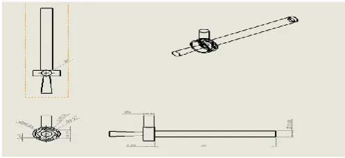
Figure 3. Vortex Tube Dimension
V.
RESULT AND DISSCUSTION
The various results are obtained from the analysis fluid flow in vortex tube is discussed in this chapter. The temperature at the cold end and hot end is taken as output.
Figure 4. Experimental Result OfEXAIR 3205 Medium Model
L/D Ratio and Cold End Temperature
Figure 5. Energy Separation In The Vortex Tube L/D=5.39
The path line clearly shows that flow separation of swirling air inside the vortex tube. The length of the vortex tube is 55mm, reducing the length of the vortex tube below 55mm give the large eddy in nearer to the hot end of the vortex tube. Below this length increase the temperature at cold end.
ORIFICE RADIOS
IN MM
COLD END
TEMPERATURE IN°C
3
23.67-26.61
2
1.60-4.10
2.5
1.60-4.12
1.5
1.60-4.12
Orifice Radius and Cold End Temperature
VI.
CONCLUSION
This work shows that reduction in length of the
vortex tube will reduce the cold end
temperature,because reduction in length of the vortex tube will affect the velocity inside the vortex generator and tube. Orifice diameter is modified and analyzed, increasing the orifice diameter increasing the temperature at cold end.
Reducing orifice radios to 2mm and 1.5mm give the cold end temperature, reducing the orifice radios below 1.5mm increasing the temperature at cold end. Hot end gap at 0.4mm give the optimum temperature 1.31°c.
VII.
REFERENCES
L/D RADIO
COLD END
TEMPERATURE IN °C
14.21
4.47-6.85
12.35
4.96-7.29
11.37
3.54-6.25
10.39
5.64-8.47
9.31
4.93-7.26
8.33
3.42-6.12
7.35
3.37-6.07
6.37
2.85-5.56
[1]. N. F. Aljuwayhel, G. F. Nellis, and S. A. Klein, "Parametric and internal study of the vortex tube using a CFD model vol. 28, pp. 442-450, 2005.
[2]. A. T. Al-omran and R. R. Ibrahim, "EFFECT OF THE COLD OUTLET DIAMETER ON THE," vol. 18, no. 2, 2005.
[3]. G. De Vera, "The Ranque-Hilsch Vortex Tube," pp. 1-10, 2010.
[4]. N. Pourmahmoud and A. R. Bramo, "THE EFFECT OF L / D RATIO ON THE TEMPERATURE SEPARATION," vol. 6, no. January, pp. 60-68, 2011.
[5]. H. M. Skye, G. F. Nellis, and S. a. Klein, "Comparison of CFD analysis to empirical data in a commercial vortex tube," Int. J. Refrig., vol. 29, no. 1, pp. 71-80, Jan. 2006.
[6]. R. S. Maurya and K. Y. Bhavsar, "Energy and Flow Separation in the Vortex Tube : A Numerical Investigation," pp. 25-32, 2013. [7]. L. H. Tang, M. Zeng, and Q. W. Wang,
"Experimental and numerical investigation on air-side performance of fin-and-tube heat exchangers with various fin patterns," Exp. Therm. Fluid Sci., vol. 33, no. 5, pp. 818-827, 2009.
[8]. Y. T. Wu, Y. Ding, Y. B. Ji, C. F. Ma, and M. C. Ge, "Modification and experimental research on vortex tube," Int. J. Refrig., vol. 30, no. 6, pp. 1042-1049, Sep. 2007.
[9]. K. Dincer, S. Baskaya, B. Z. Uysal, and I. Ucgul, "Experimental investigation of the performance of a Ranque - Hilsch vortex tube with regard to a plug located at the hot outlet Int. J. Refrig., vol. 32, no. 1, pp. 87-94, 2009.