Dynamic Stress Analysis with Different boundry
Conditions by ISO-Surface behaviour
Parth K Pandya
1, Anuj Kumar Sehgal
2Scholar (M.Tech), Sharda University Greater Noida,U.P. India Assistant Professor, D.o.M.E, Sharda University, Greater Noida, U.P. India
Abstract— Any CAE (Computer Aided Engineering) software the first result will be in contour manner which comes with the colour scale (Legend).But that will only give rough scenario about what is happening inside the layers in object when force is applied. That result is in iso-surface mode. Different members like Slabs, Beams and beam column joints behavior can be decided by the plane stress. An iso-surface is a three-dimensional analog of an iso-line. It is a surface that represents points of a constant value within a volume of space. Computer aided investigations on a solid object are carried out using the ANSYS 15.0 software to verify maximum stress and its location. To predict detailed stress values with 3D model created itself by Ansys 15.0 15. Solid object is made with the two imprinted faces on it for the application of dynamic analysis. Dynamic analysis is done by dividing time in to fractions & after that iso-surface is studied. Material used during the research is structural steel due to its importance and availability. The behavior of iso-surface changes with respect to the boundary condition viz. contact area of force. Visual representations of iso-surfaces are ubiquitous in the scientific and engineering literature. In this paper, we present techniques to assess the behavior of iso-surface extraction codes. More concretely, we derive formulas for the expected order of accuracy (or convergence rate) of several iso-surface features, and compare them to experimentally observed results in the selected codes. This technique is practical: in two cases, it exposed actual problems in implementations. We provide the reader with the range of responses they can expect to encounter with iso-surface techniques, both under "normal operating conditions" and also under adverse conditions. Armed with this information the results of the verification process--practitioners can judiciously select the iso-surface extraction technique appropriate for their problem of interest, and have confidence in its behavior. The material taken is structural steel in which the linear behavior is taken consideration in this case.
I. INTRODUCTION
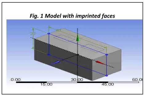
A block of 20*40*20 106 mm is modelled by using Ansys 15.0 software and two faces are imprinted on that to divide the whole surfaces into different surfaces. The two rectangular surfaces is taken here as imprinted faces
.
Imprinted faces are command used in Ansys 15.0 together with the extrude option. The meshing is the next step to define the number of nodes and elements as per the FEM analysis. Finite element analysis (FEA) involves solution of engineering problems using computers.
Nonlinear finite element method models for ultimate strength analysis of steel stiffened-plate structures under combined biaxial compression and lateral pressure actions have been studied [1], as part I AND IN Part II the stiffened panels surrounded by strong support members such as longitudinal girders and transverse frames are studied. In similar to Part I, some important factors of influence such as structural dimensions, initial imperfections, loading types and computational techniques in association with ultimate limit states are studied. Some useful insights in terms of nonlinear finite element method modeling are developed using ANSYS 15.0 code together with the ALPS/ULSAP semi-analytical method, the latter being for the purpose of a comparison.
II.
MATERIAL
Material chosen here is Structural Steel having Density 7.85 g/cm3, poisons Ratio 0.3, Young’s modulus 2 x 10¹¹Pa, Tensile Yield Strength 2.5 x 10⁸Pa, Compressive Yield Strength 2.5 x 10⁸ Pa, Bulk Modulus1.7 x 1011Pa and Shear Modulus 7.69 x 10¹⁰Pa. Ansys 15.0 15 has default properties of this material which is being taken from Fatigue Data at zero mean stress comes from 1998 ASME BPV Code, Section 8, Division 2.The analysis has been done by considering these mechanical properties of material.
III.
MESHING
Finite Element Analysis will comprise of discretizing the solution in small elements. The end points of elements are nodes and whole domain would be known as Element. Meshing is discretizing of domain into sub-domain.
In our case of rectangle object the meshing done can be represented by Figure 2. It comprises the data of number of elements and number of nodes used in the default meshing. Default meshing is course meshing. Number of elements 1221
used is and number of nodes are 2386.
From the meshed path you can easily observe that the imprinted faces have common mesh pattern. Which is having triangular type of meshing default taken by Ansys 15.0. Next step is for boundary conditions.
IV.
BOUNDRY CONDITONS
Boundary conditions are the degree of freedom allowed for the object as well as loading conditions. We have given one surface of object fixed in translation and rotation (0 Degree of Freedom). A is fixed support of object, B &C are forces applied on imprint faces.
In Ansys 15.0 dynamic analysis force application comes with the fraction of time. The three loading conditions taken on
Imprint faces B & C are as shown in Table 1.
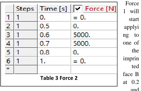
The Load is given in this particular manner. The loads are applied by dividing the time in 10 fractions. The Force one is applied from 0.2 to 0.4 and Force 2 is applied from 0.6 to 0.7
fraction of time as shown in Table2.
Force 1 will start applyi ng to one of the imprin
ted face B at 0.2 and application would be end at 0.4, same way Force 2 would start applying at imprinted face C at 0.6 and application of Force 2 will end on 0.7 time fraction.
Force 1(N)
Force 2(N)
2500
5000
3500
6000
4500
7000
Table 1 Forces Magnitude
Fig. 2 Mesh
Fig. 3 Boundary Conditions with Imprinted Face B & C
Table 2Force 1
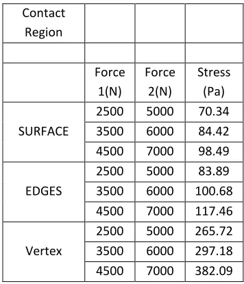
Fig. 5 Three Contact Regions
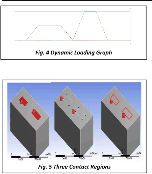
The contact surface of force is considered in three manner (1) Surface (2) Vertex (Point) (3) Edges with three different incremental loading conditions for an
experimental value and for studying iso-surface behavior. After applying the loads as per the fractional time as discussed further the final results with time variations comes.
Next is going to solutions where we will have to start the calculation at each and every nodes. Each nodes contains the material property of applied material and that is being solved by stiffness matrix method.
V. SOLUTIONPROCESS
Finite Element Method (FEM) is the one by which we can find the stress, stain, deformation etc. FEM comprises of three very basic steps which any CAE software almost adopts
1. Pre Processing :Apply material & Boundary Conditions 2. Solver :After meshing generation solve the equations 3. Post Processing : Generate desired result i.e Stress ,Strain. Pre-processing defines as material selection and boundary conditions has been done. By stiffness matrix method the solution starts. The method is as below.
By taking any material’s elastic property and try to consider it as a spring with stiffness K, Force applied is F and Change in length is ΔL. This equations for stress and strain
Equation 1 Stress Strain relation and Stiffness
Thus, The final solution as a stiffness matrix over every node as
R= [K] {u}-[F]
R= Reaction Matrix u= Displacement Matrix K= Stiffness Matrix F= Load Matrix
VI. RESULTS
First the results of applying Force1 2500N and Force2 5000N in Dynamic manner on surface contact region these are
two result windows where exactly Iso-surface behavior for von misses stresses are observed. Stress value is 70.34Pa. The result for applying same magnitude of force for contact region in Dynamic manner on edge region is as below. Von Misses stress value is 83.89Pa because surface area is edges of imprinted faces as shown in Figure4.
When applying on vertexes (Points) or the corners of imprinted faces in Dynamic stress conditions the induced Von Misses stresses are 265.72Pa.
Fig. 4 Dynamic Loading Graph
−
−
−
+
−
−
+
−
−
+
−
−
=
−
P
u
u
u
u
u
k
k
k
k
k
k
k
k
k
k
k
k
k
k
k
k
R
0
0
0
0
0
0
0
0
0
0
0
0
0
0
0
0
0
0
0
0
5 4 3 2 1 4 4 4 4 3 3 3 3 2 2 2 2 1 1 1 1 1Fig. 6 Surface Contact Region Stresses
Fig. 6 Surface Contact Region Stresses
VII. DISCUSSION
As seen from above result The iso-Surfaces is one way of post processing so that the activity occurs inside the layers of object depending upon material property during the loading conditions can easily guide precisely what happens inside the surface layers of object. Studying the surface which basically is 2D is very necessary because first part engaged during any loading is the surface of the object.
The behavior of iso-surface is monitored after application of force. By studying the behavior how the stress travels inside the object is something very noticeable. Elastic and plastic region of any structure is more defined and in some cases unknown materials with all Isotropic, Orthotropic and Anisotropic is discoverable.
When force dynamically applied to surface region of body the iso-Surface behavior as seen in figure 7 will be limited in only one plane (say YZ plane). Further, during the edge region of dynamic force the iso-surface will start immerging in two different plane together, means (say YZ and XZ plane) ,and during edge region loading immerging the iso-surfaces will be having less stress value than surface region. By changing the dynamic loading condition to vertex the stress values will be highest and the iso surface around the surface region and edge region will be having less stress value than of vertex.
The reason of taking Dynamic condition is because the when Force is applied dynamically at the time of application of force the blue layer or iso-surface passes through whole object which shows the elastic behavior of material and later at force’s highest value plastic and fracture region as well Factor of safety we can discover. For all three loading condition with different contact region will be different. Study of three different force magnitudes with different contact region is
Table 4 Stresses for different Contact Region
Contact
Region
Force 1(N)
Force 2(N)
Stress (Pa)
SURFACE
2500 5000 70.34 3500 6000 84.42 4500 7000 98.49
EDGES
2500 5000 83.89 3500 6000 100.68 4500 7000 117.46
Vertex
2500 5000 265.72 3500 6000 297.18 4500 7000 382.09
VIII. CONCLUSION
Dynamic loads when applied to imprinted faces it is very easy to understand how the load penitrates and travel through layers inside the body by iso-surfaces.The stress values become larger when the contact region of force is decresed and from contact region surface to edges will result in iso-surface from more than one plane will be result. Inedge contact region the iso-surface will have lesser stress values near surface region same way moving result to vertex(Point) wil give result to the lesser and\or negligible stress value over surface and edge region of imprinted faces.
IX. FUTURESCOPE
Study of iso-surface will open the gates of studying different material’s mechanical and thermal properties including CFD (Computational Fluid Dynamics) & fatigue studies.Fracture mechanics and fracture growth depending on the inner layers and chemical composiotion can be studied by the iso-surface and dynamic analysis.
X. ACKNOWLEDGMENT
I am very much thankful to the Department of Mechanical Engineering, Sharda University to provide the software support and undoubtedly my family during entire research.
REFERENCES
[1] F. C. Filippou, “Finite Element Analysis of Reinforced Concrete
Structures Finite Element Analysis of Reinforced Concrete
[2] S. A. Kulkarni, B. Li, and W. K. Yip, “Finite element analysis of precast hybrid-steel concrete connections under cyclic loading,” Journal of Constructional Steel Research, vol. 64, no. 2, pp. 190–201, 2008.
[3] Y. Luo, A. Li, and Z. Kang, “Parametric study of bonded
steel-concrete composite beams by using finite element analysis,” Engineering Structures, vol. 34, pp. 40–51, 2012.
[4] M. Gyimesi, V. Zhulin, and D. Ostergaard, “Particle trajectory
tracing in ANSYS 15.0,” Nuclear Instruments and Methods in Physics Research, Section A: Accelerators, Spectrometers, Detectors and Associated Equipment, vol. 427, no. 1–2, pp. 408–411, 1999.
[5] H. Karagülle, L. Malgaca, and H. F. Öktem, “Analysis of active
vibration control in smart structures by ANSYS 15.0,” Smart Materials and Structures, vol. 13, no. 4. pp. 661–667, 2004.
[6] Y. Nakasone, S. Yoshimoto, and T. A. Stolarski, Engineering
Analysis with ANSYS 15.0 Software. 2006.
[7] T. Etiene, C. Scheidegger, L. G. Nonato, R. M. Kirby, and C. T.
Silva, “Verifiable visualization for iso-surface extraction,” in IEEE Transactions on Visualization and Computer Graphics, 2009, vol. 15, no. 6, pp. 1227–1234.
[8] T. Athawale and A. Entezari, “Uncertainty quantification in
linear interpolation for iso-surface extraction,” IEEE