IJSRSET1738163 | Received : 20 Nov 2017 | Accepted : 08 Dec 2017 | November-December-2017 [(3)8: 498-503]
© 2017 IJSRSET | Volume 3 | Issue 8 | Print ISSN: 2395-1990 | Online ISSN : 2394-4099 Themed Section: Engineering and Technology
498
Review of Analysis of Power System Oscillation Damping &
Voltage Stability Improvement Using SSSC In A Multi-Machine
System
Amit Kumar
1, Pardeep Nain
21
M.Tech Scholar EE Department OITM, Hisar, Haryana, India
2
Assistant Professor, EE Department OITM, Hisar, Haryana , India
ABSTRACT
The planning and operation condition of electrical power systems are changing due to a variety of causes. FACTS controller helps in raising dynamic stability limit and provide better power flow control. Static synchronous series compensator (SSSC) is one of the important members of series FACTS controller. In this paper is presented the effect of SSSC for damping power system oscillation. Interconnection of electric power systems is becoming increasingly widespread as part of the power exchange between countries as well as regions within countries in many parts of the world. There are numerous examples of interconnection of remotely separated regions within one country. In cases of long distance AC transmission, as in interconnected power systems, care has to be taken for safeguarding of synchronism as well as stable system voltages, particularly in conjunction with system faults. With series compensation, bulk AC power transmission over very long distances (over 1000 km) is a reality today. These long distance power transfers cause, however, the system low-frequency oscillations to become more lightly damped. As a result, many power network operators are taking steps to add supplementary damping devices in their systems to improve the system security by damping these undesirable oscillations. With the advent of voltage sourced converter-based series compensation, AC power system interconnections can be brought to their fullest benefit by optimizing their power transmission capability, safeguarding system stability under various operating conditions and optimizing the load sharing between parallel circuits at all times. This Paper reports the results of simulation studies that are carried out to investigate the effectiveness of a three phase Static Synchronous Series Compensator (SSSC) compensation scheme in damping power system oscillations in multi-machine power systems. Application of static synchronous series compensator (SSSC) based damping controller for enhancement of power system stability is throughout investigated in this paper. SSSC is effectively utilized for power flow control in the power system. A SSSC-based damping controller is proposed for rotor angle stability enhancement and to eliminate the power oscillation damping in power system. To improve the rotor angle stability and power oscillation damping in system an supplementary signal can be superimposed as a power flow control signal for SSSC damping controller. Speed deviation of rotor is taken as the input signal to the SSSC damping controller
Keywords : SSSC, PowerOscillations Damping(POD), FACTS controller.
I.
INTRODUCTION
Electric power systems are constituted by the interconnection of a huge number of different components and hence they are electromechanically coupled. They can be considered among the most complex systems to be planned and safely operated. This complexity arises as a consequence of large amount of devices contemporaneously in operation, each one with its own internal dynamics, which
however interacts with each other, giving rise to a complex collective behavior. The wide geographic extension of electric power systems that can span entire countries and even continents adds complexity to the issue connected to their analysis and control .
variables being bounded. So that practically the entire systems remain intact. Power system stability can be classified as voltage stability, rotor angle stability and frequency stability. Among these types, inter-area oscillation comes under rotor angle stability.
For any given situation, the rotor angle stability of the system depends on whether or not the deviations in angular positions of the rotors result in sufficient restoring torque. Loss of synchronism can occur between one machine and the rest of the system, or between groups of machines, with synchronism maintained within each group after separating from each other. The change in electromagnetic torque of a synchronous machine following a perturbation can be resolved into two components.
Growth of electric power transmission facilities is restricted despite the fact that bulk power transfers and use of transmission systems by third parties are increasing. Transmission bottlenecks, non-uniform utilization of facilities and unwanted parallel-path or loop flows are not uncommon. Transmission system expansion is needed, but not easily accomplished. Factors that contribute to this situation include a variety of environmental, land-use and regulatory requirements. As a result, the utility industry is facing the challenge of the efficient utilization of the existing AC transmission lines. Thus, the transmission systems are being pushed to operate closer to their stability and thermal limits. Although electricity is a highly engineered product, it is increasingly being considered and handled as a commodity. Thus, the focus on the quality of power delivered is also greater than ever. Series capacitive compensation of power transmission lines is an important and the most economical way to improve power transfer capability, especially when large amounts of power must be transmitted through long transmission lines. However, one of the impeding factors for the increased utilization of series capacitive compensation is the potential risk of Subsynchronous Resonance (SSR), where electrical energy is exchanged with turbine-generator shaft systems in a growing manner which can result in shaft damage.
II.
TRANSMISSION LINE SERIES
COMPENSATION
2.1 Steady-state voltage regulation
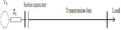
A series capacitor is capable of compensating the voltage drop of the series inductance of a transmission
line. Referring to Figure 2.1, during light loading (Load L), the voltage drop on the series capacitor is low. When the load increases (Load H) and the voltage drop on the line becomes larger, the contribution of the series capacitor increases and, therefore, the system voltage at the receiving line end will be regulated as desired.
Figure 2.1. A simple radial power system and voltage drop compensation with a series capacitor
2.2 Increase in the power transfer capability by raising the first swing stability limit
A substantial increase in the stability margin is achieved by installing a series capacitor. The series compensation will improve the situation in two ways: it will decrease the initial generator load angle corresponding to a specific power transfer and it will also shift the power-load angle (P-δ) characteristic upwards. This will result in increasing the transient stability margin.
2.3 Increase in power transfer
The increase in the power transfer capability as a function of the degree of compensation for a transmission line can be illustrated using the circuit and the vector diagram shown in Figure 3.1. The power transfer on the transmission line is given by:
sin
sin
(1
)
S R S R
line C line
V V
V V
P
X
X
X
k
Where k is the degree of compensation defined as
C line X k
X
The effect on the power transfer when a constant load angle difference is assumed. Practical compensation degree ranges from 20 to 70 percent. Transmission capability increases of more than two times can be obtained in practice.
close. Therefore, the power transmitted in each line will be similar. The voltage drop in both relationship between the line currents IL1 and IL2 can be expressed
as:
IL1ZL1= IL2ZL2
If overloading the lower thermal rating line, is to be avoided (i.e., IL2 ≤ IL2max), then the full power
capacity of the other line, L1, will never be reached (i.e.,
IL1< IL1max).
For example, consider the case when L1 is a four
conductor bundle (quad) circuit configuration, whereas L2 has a two conductor bundle (twin) circuit
configuration. If the conductors of the two bundles are identical, then L1 has twice the rating of L2. The
inductive reactances of the two lines, however, are very close. If a series capacitor is installed in the higher thermal rating line, both transmission lines can operate at their maximum capacity when the appropriate degree of compensation is provided (50% in this case).
III.
THE STATIC SYNCHRONOUS SERIES
COMPENSATOR
The Static Synchronous Series Compensator is a series-connected converter-type FACTS device. Although no stand-alone SSSC has been in service, the series converter of the Unified Power Flow Controller (UPFC) at the Inez Substation of the American Electric Power (AEP) system in Kentucky, USA represents an SSSC .SSSC uses VSC to inject into the transmission line an almost sinusoidal voltage with independently controllable magnitude and phase angle. The SSSC uses a controller that can rapidly change the injected voltage into the transmission line. This gives the SSSC the capability to dynamically exchange reactive and/or active power with the power system. This injected voltage is almost in quadrature with the line current. The very small part of the voltage which is in phase with the line current provides the losses in the converter.
Because capacitors are cheaper than power electronic elements, SSSC is less competitive than fixed series compensation in terms of price. In order to reduce the overall cost, a hybrid scheme can be employed. In such a scheme, the capacitive compensation in each phase is shared between an SSSC and a fixed capacitor.
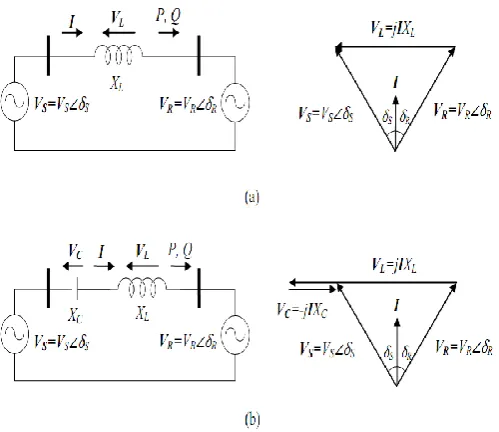
Consider a simple two-machine power system model without and with a series capacitor compensation and the corresponding phasor. In this model, it is assumed
for simplicity that the transmission line resistance is negligible and, therefore, the line is represented by an inductive reactance. Moreover, it is assumed that the machines at both ends are represented by as constant amplitude sinusoidal voltages at synchronous frequency. Figure 3.1(b) shows that the series capacitor provides a lagging quadrature voltage with respect to the line current and this capacitive voltage drop opposes the leading voltage drop across the inductor. It can be observed from Figure 3.1(b) that the current and, in turn, the power flow increases in the system.
Figure 3.1. A schematic diagram of a simple two-machine power system and its vector diagrams: (a) without series compensation, (b) with series capacitor
compensation.
The active (real) power at the receiving-end bus for the uncompensated system in Figure 3.1(a) is given by
2
sin(
)
sin
S R
S R
L L
V V
V
P
X
X
where VS and VR are the magnitudes of the sending and
receiving end voltages respectively, ( it is assumed that V=VS=VR),
(is called the load angle) is the angle betweenthe sending and receiving end voltages (
S
R) and XL isthe transmission line inductive reactance.
For the series capacitor compensated system (Figure 3.1(b)),
2 2 2 2
sin sin sin sin
( ) (1 )
(1 C)
eff L C L
L L
V V V V
P
X
X X X X k
X X
Where XCs the capacitor reactance,
X
eff =XLXC is theeffective reactance, and k= C
L X
X is the degree of series
compensation (0k<1)Figure 3.2 shows the normalized active power versus the load angle of the series capacitor compensated system shown in Figure 3.1(b) as a parametric function of the degree of series capacitive compensation. It is clear that series capacitor compensation increases the transmitted power by a fixed percentage of that transmitted by the uncompensated line at a given δ and that higher power transfer is achieved by increasing the degree of the compensation.
IV.
THE STATIC SYNCHRONOUS SERIES
COMPENSATOR MODELED
4.1. Phase Control Technique for SSSC
The modeled SSSC circuit with its two six-pulse VSCs and their series transformers.The converters are connected in series to the transmission line through two banks of lossless three-phase single-phase two-winding transformers with no saturation. The dc sides of the converters are connected in parallel and share the same dc busThe change in the phase shift between the SSSC output voltage and the line current results in the change of the dc capacitor voltage Vdc , which ultimately
changes the magnitude of the SSSC output voltage VSSSC and the magnitude of the transmission line current line I.
4.2. PWM Technique
SSSC is modeled as a three-phase, PWM-controlled two-level VSC. The SSSC is modeled in detail, based on an ideal representation of the converter valves and diodes. RC parallel snubber circuits are used to reduce numerical oscillations due to switching, while a series inductance is employed at the converter output to smooth the output current. The series transformer is modeled as an ideal, three-phase, two-winding, Y-Δ connected transformer. The modeled PWM-controlled SSSC basic circuit. The control of the SSSC is achieved by applying SPWM control technique with a small modification. A third harmonic of appropriate amplitude is added to the sinusoidal control waveform to increase the fundamental component of the SSSC output voltage . The requency modulation ratio mf =15 is chosen to eliminate the even harmonics and moreover, since 15 is a multiple of 3, to cancel out the most dominant harmonics from the line-to-line output voltages (in the
three-phase converters, only the harmonics in the line-to-line voltages are of concern). The control and triangular waveforms are synchronized with respect to the reference voltage at left side Bus, instead to the transmission line current, which was thecase for the phase controlled SSSC.
V.
CONCLUSION
This thesis analyze the performance of a SSSC in a multi machine system in the presence of different faults is considered. The output results illustrate that the power system oscillations are damped out very rapidly with the help of SSSC based damping controllers in few seconds. The study reveals that SSSC is proficient to enhance the power flow through the transmission line by injecting a fast changing voltage in series with the line. The injected voltage is in quadrature with line current and hence it can provide both inductive and capacitive compensation. PWM based and phase controller have both disadvantages and advantages, which makes the design process somewhat complicated. The dc voltage pre-set value in PWM-based controllers has to be carefully selected. As the modulation ratio lies between zero and one, the dc voltage should not be lower than the maximum of the requested SSSC output phase voltage in order to obtain proper control. On the other hand, if the dc side voltage is too high, the rating of both the GTO valves and dc capacitor has to be increased, which means higher installation costs. Not only that, a higher dc side voltage means a lower amplitude modulation ratio, and the lower modulation ratio results in higher harmonic distortion. Phase control allows the dc voltage to change according to the power system conditions, which is clearly advantageous, but it requires a more complicated controller and special and costly series transformers.
VI.
REFERENCES
[1]. O. Ziaee, F. F. Choobineh, "Optimal location- allocation of TCSC devices on a transmission network", IEEE Trans. on Power Systems, vol. 32, no. 1, pp. 94-102, Jan. 2017.
[3]. D. A. Ingole, Prof. Dr. V. N. Gohokar; Voltage Stability Improvement In Multi-bus System Using Static Synchronous Series Compensator 1st International Conference on Power Engineering, Computing and CONtrol, PECCON-2017, 2-4 March 2017, VIT University, Chennai Campus. [4]. A. Ganga Dinesh Kumar, N. V. Ramana ,
Integrating SSSC with Variable Structure Observer based Optimal Controller for Damping Frequency Oscillations of Deregulated Power System ; International Journal of Applied Engineering Research ISSN 0973-4562 Volume 12, Number 14 (2017) pp. 4191-4198 Research India Publications.
[5]. Abhinav L. Purkar, Prof. Prasanna D Bharadwaj; Improvement of Multi-Machine Power System Stability Using SSSC ;International Journal for Research in Applied Science & Engineering Technology (IJRASET) ; Volume 4 Issue IV, April 2016 IC Value: 13. 98 ISSN: 2321-9653. [6]. Abhinav L. Purkar, Prof. P. D. Bharadwaj;
Enhancement of Multi Machine Power System Stability Using SSSC with Power Oscillation Damping (POD) Controller;Print ISSN : 2395-1990, Online ISSN : 2394-4099, Volume 2, Issue 3, pp. 822-827, May-June-2016.
[7]. C. Udhaya Shankar, Dr. Rani Thottungal, Mythili, "voltage stability improvement and power oscillation damping using static synchronous series ; compensator (SSSC)", IEEE Sponsored 9th International Conference on Intelligent Systems and Control (ISCO)2015.
[8]. R Visakhan, Rahul R, Asha Anu Kurian,
"Comparative study of PSS and FACTS-POD for power system performance enhancement", 2015 IEEE Instrumentation, Control and Computing (PICC).
[9]. Maninder rohal , Mr. Ravi, "Application of SSSC Based Power Oscillation Damping Controller for Transient Stability Enhancement of Multimachine system for Unsymmetrical Faults", Power India International Conference (PIICON), 2014 6th IEEE.
[10]. Shashi Gandhar, Jyoti Ohri, Mukhtiar Singh, "Application of SSSC for Compensation
Assessment of Interconnected Power
System"2014 IEEE 6th India International Conference on Power Electronics (IICPE). [11]. C. Anitha, P. Arul "Enhancement of Voltage
Stability in Transmission System Using SSSC
"International Conference on Circuit, Power and Computing Technologies [ICCPCT] 2014. [12]. Khadanga, R. K. , Satapathy, J. K. "Gravitational
search algorithm for the static synchronous series compensator based damping controller design" Students' Technology Symposium (TechSym), 2014 IEEE, Feb. 28 2014-March 2 2014 Page(s):356-361
[13]. Kotwal, C. , Sangala, U. ; Pillai, G. N. "Improving
power oscillation damping using static
synchronous series compensator" Published in: India Conference (INDICON), 2013 Annual IEEE, 13-15 Dec. 2013Page(s):1-6.
[14]. Tossaporn Surinkaew, Issarachai Ngamroo and Worawat Nakawiro, "Robust Power Oscillation Damper Design for DFIG-based Wind Turbine", 2013 10th International Conference on.
[15]. S Arun Kumar, C Easwarlal, M Senthil Kumar, "Multi Machine Power System Stability Enhancement Using Static Synchronous Series Compensator", 2012 International Conference on
Computing, Electronics and Electrical
Technologies [ICCEET].
[16]. M. Farahani ; Damping of subsynchronous oscillations in power system using static synchronous series compensator;Volume: 6, Issue: 6, June 2012; International Conference on
Computing, Electronics and Electrical
Technologies [ICCEET].
[17]. Unal, I. Rai, D. , Faried, S. O. "Damping power system oscillations using an SSSC-based hybrid series capacitive compensation scheme" PowerTech, 2011 IEEE Trondheim, 19-23 June 201, Page(s):1-6
[18]. Borre, A. C. Ortiz, A. , Watanabe, E. H. & Sulkowski, W. "Synchronous generator power oscillations damped by using TCSC or SSSC working as a variable reactance" International Conference on Electrical Machines and Systems (ICEMS), 2011 I20-23 Aug. 2011, Page(s):1-6. [19]. Faridi, M. Maeiiat, H. ; Karimi, M. ; Farhadi, P.
“Power system stability enhancement using static synchronous series compensator (SSSC)" Computer Research and Development (ICCRD), 2011 3rd International Conference on (Volume:3 )11-13 March 2011, Page(s):387-391.
2011-2011 IEEE Region 10 Conference , 21-24 Nov. 2011, Page(s): 928-932.
[21]. Vishwakarma, S. Tripathi, R. K. "Transient energy dissipation and damping improvement using STATCOM & SSSC" Power, Control and Embedded Systems (ICPCES), 2010 International Conference on, Nov. 29 2010-Dec. 1 2010, Page(s):1-4.
[22]. H. Taheri , S. Shahabi, Sh. Taheri, A. Gholami "Application of Synchronous Static Series Compensator (SSSC) on Enhancement of Voltage Stability and Power Oscillation Damping". EUROCON 2009, EUROCON '09. IEEE.
[23]. Li Juan , Dong Sheng ; Zhou Xingfu"A Nonlinear Control Approach to Increase Power Oscillations Damping by SSSC" Computer and Electrical Engineering, 2008. ICCEE 2008. International Conference on, 20-22 Dec. 2008 Page(s):734-738. [24]. Anil C. Pradhan and P. W.
Lehn"Frequency-Domain Analysis of the Static Synchronous Series Compensator" IEEE TRANSACTIONS ON POWER DELIVERY, VOL. 21, NO. 1, JANUARY 2006.
[25]. S. Salem and V. K. Sood, "Modeling of SSSC with EMTP RV, " IEEE ISIE 2006, July 9-12, 2006, Montréal, Québec, Canada.
[26]. Fawzi. A. Rahman Al Jowder, and Boon-Teck Ooi"Series Compensation of Radial Power System by a Combination of SSSC and Dielectric
Capacitors" IEEE TRANSACTIONS ON
POWER DELIVERY, VOL. 20, NO. 1, JANUARY 2005.
[27]. F. A. R. Al Jowder, B. T. Ooi, "Series Compensation of Radial Power System by a Combination of SSSC and Dielectric Capacitors, " IEEE Transactions on Power Delivery, Vol. 20, No. 1, January 2005, pp. 458-465.
[28]. Chandrakar, V. K. , Kothari, A. G. "Fuzzy logic based static synchronous series compensator (SSSC) for transient stability improvement" Electric Utility Deregulation, Restructuring and Power Technologies, 2004. (DRPT 2004). Proceedings of the 2004 IEEE International
Conference , Volume:1, 5-8 April