Considerations in Designing DCI (Data Centre
Interconnect) in Full Mesh VPLS/ Multicast Enable WAN
over OTV Tunnel
Arsalan Iqbal
*, Steve Benoit, Usman Dar
Georgian College, IT Department, Barrie, L4M3X9, Canada.
* Corresponding author. Tel.: +1-416-997-4022; email: [email protected] Manuscript submitted August 4, 2016; accepted March 20, 2017.
doi: 10.17706/ijcce.2017.6.2.127-136
Abstract: VPLS/ MPLS is one of the most popular Wide Area Network (WAN) technologies used today by service providers. VPLS depends on pseudowires (PW) within Multiprotocol Label Switching (MPLS) network to emulate Ethernet connectivity in a full mesh topology, to multiple remote sites, sharing an Ethernet broadcast domain. As IP multicast services continue to be offered, many customers find it desirable to extend their multicast applications to remote sites, where traditional technologies fail to support such connectivity. A layer-2 VPN service using VPLS supports the extension of multicast services to remote sites. In this paper, the impact of a full mesh VPLS with the interoperability of Cisco Overlay Transport Virtualization (OTV) and multicast traffic has been analyzed. The paper concludes that an inadequately designed full mesh VPLS based WAN can have a significant negative impact on overall WAN performance in terms of reachability and packet loss for data, voice, and multicast traffic on the same customer edge (CE) device. The paper further proposes a design solution to avoid drastic impacts on the overall WAN performance when a large amount of multicast traffic is to be transported.
Key words: VPLS, OTV, multicast, iSCSI, InterMapper, multiprotocol label switching (MPLS).
1.
Introduction
The extension of layer 2 connectivity over geographically disperse remote sites is a requirement of many modern data center solutions. This setup provides business continuity and resilience in the form of high availability, responsiveness, data replication, high performance, and disaster recovery. This data center design depends on the underlying physical architecture, the type of layer 2 and 3 protocols used, and the applications running in the enterprise [1]. WAN connectivity can be achieved by a number of ways that include traditional ATM, Frame relay, X.25, TLS (Transparent LAN Services) or the more modern MPLS-VPLS.
Virtual Private LAN Services (VPLS) is a class of Virtual Private Network (VPN) that supports the connection of multiple sites in a single bridged domain over a managed IP/MPLS network. VPLS presents an Ethernet interface to customers, simplifying the LAN/WAN boundary for Service Providers and customers, and enabling rapid and flexible service provisioning, because the service bandwidth is not tied to the physical interface. All services in a VPLS appear to be on the same Local Area Network LAN, regardless of location.
by a full mesh of tunnels, enabling any-to-any connectivity [2]. In essence, a VPLS glues several individual LANs together across a packet-switched network provided by scalable-shared IP/MPLS backbone to appear and function as a single LAN. The underlying MPLS can provide Traffic Engineering (TE) functionality, which includes the Quality of Service (QoS) guarantees [3], resource optimization, and fast failure recovery. Each service router has a VPLS service instance (also referred as a Virtual Switching Instance, or VSI) [4].
Each VSI performs MAC address learning and constructs a table that maps MAC addresses to the corresponding MPLS paths (pseudo wires) [4] or the customer access ports. By using VPLS services, customers can significantly expand the coverage of their private (LAN) while keeping the routing control to themselves. It is an ideal solution for non-IP protocols (e.g., Interwork Packet Exchange, IPX) within a campus [5]. VPLS service instances are provisioned in the customer facing service routers involved in the service, and multiple services in the same router are isolated by the service instances and do not exchange traffic. As an important part of any Ethernet bridged network, VPLS supports VLAN tagging, double tagging (Q-in-Q), and VLAN translation [6]-[11]. Fig. 1 shows the emulated LAN provided by the MPLS/VPLS network connecting multipoint sites PE1 and PE2 via P1/ P2 and P3/P4.
Fig. 1. MPLS VPN architecture [10].
Overlay Transport Virtualization [7], [8] is a technology introduced by Cisco Inc. in the Nexus 7000 and ASR 1000 platforms. OTV allows customer to deploy virtual computing resources and clusters across geographically distributed data center, delivering transparent workload mobility, business resiliency, and superior computing resource efficiencies. Customers can now deploy DCI between sites without changing or reconfiguring the existing network design. One of the key OTV features is to extend Layer 2 LANs over any network. OTV uses IP-encapsulated MAC routing, and works over any network that supports IP, and is designed to scale across multiple data centers.
Messaging Service), Simple Mail Transfer Protocol (SMTP) or SYSLOG message to advise staff of a condition that could escalate into a problem.
The paper is organized as follows, Section 1 has been the introduction; Section 2 defines the overall system design; problem definition and the impact will be addressed in Section 3; Section 4 analyzes the different scenarios that can lead to a proper design; a workable DCI design has been proposed in Section 5; and the conclusion in Section 6 summarizes the study.
2.
System Design
The physical architecture is modeled by connecting geographically distributed remote sites using service provider VPLS. This MPLS based VPLS service is totally transparent to customers. In this structure, customers have the choice to enjoy both a layer 2 and layer 3 connectivity depending on network infrastructure need and requirement.
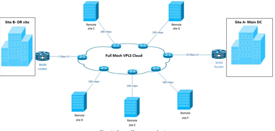
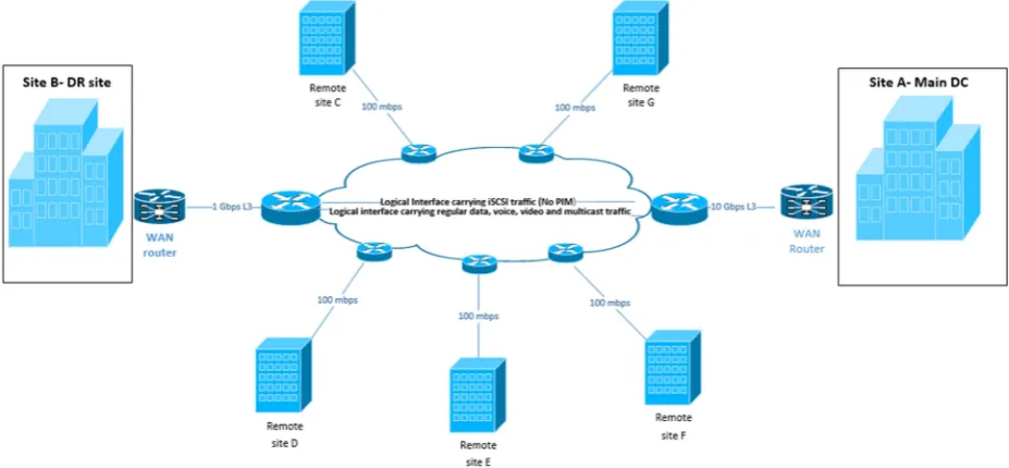
Fig. 2 shows the overall system design for the implementation of this study. Main data centre located at site A is connected to data center B (site B – Disaster Recovery (DR) site) through VPLS cloud on the WAN. Other remote sites are also connected to the VPLS cloud. This VPLS cloud emulates a big layer 2 switch providing connectivity and visibility between all the sites.
Fig. 1. Overall system design.
The physical connection between the main site and PE equipment is a 10 Gbps link, the connection between Data Centre B and PE equipment is at 1 Gbps speed while all other remote sites are connected using 100 mbps speed to the service provide edge equipment.
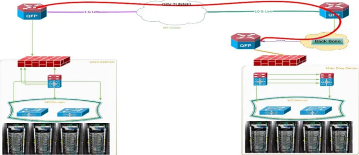
Data, voice, video and multicast traffic has been transported between all the sites. While, along with all other traffic, iSCSI traffic transport is only between the main data center and DR site. The iSCSI traffic is transported between the two sites through Cisco overlay transport virtualization. OTV provides a layer 2 extension between the two sites for data center interconnect. Fig. 3 below shows the DCI design between the two sites.
Fig. 2. DCI (Data Centre Interconnect) using OTV.
Fig. 3. Multicast operation.
3.
Problem Definition and Impact
Problem Definition
3.1.
To test interoperability between all the related technologies, a multicast session was established at site B (DR site). At the DR site, a computer system/disk imaging operation was started on a server computer in a server vlan and 15 client desktop computers on a client vlan joined the session. Both servers and client resided in the same site (site B). In a typical multicast operation once multicast tree is formed traffic follows the shortest path. However, in this test the traffic was flooded in the whole VPLS based WAN.
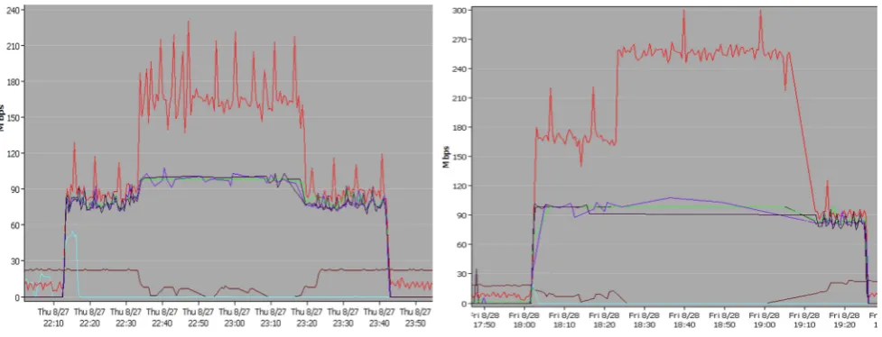
Imaging operation started at 10:10 pm at the DR site. The outgoing traffic generated by the imaging operation was between 150 mbps and 210 mbps on a 1 Gbps circuit. All of the remote sides started receiving multicast traffic at the inbound direction at 100 mbps on a 100 mbps circuit. Now that the capacity of the circuit/ link was 100 mbps and there was no bandwidth left for the other data/voice/control traffic thus dropping connectivity with the main site.
Fig. 5 shows the InterMapper graph of traffic being flooded in the WAN. OR-B102A is the router at the DR site sending traffic at the outbound direction. All other remote sites are receiving the same multicast traffic at the inbound direction.
the remote sites were receiving the multicast traffic at 100 mbps on a 100 mbps circuit. With the second test again connectivity to the remote sites on the full mesh VPLS was lost because of no bandwidth availability.
During both tests, the multicast routes were verified on the remote sites router and no client computers had joined the active multicast session at site B.
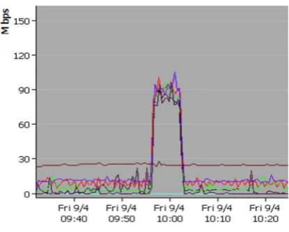
Fig. 7 and Fig. 8 show the results for some more tests with less imaging traffic. The graphs shows that out bound traffic from the DR site to be 95 mbps and all remote sites receiving the same traffic at almost 90 mbps.
Fig. 4. Multicast traffic flooding. Fig. 5. Multicast traffic flooding at 250 mbps.
Fig. 6. Multicast traffic flooding at 90 mbps. Fig. 7. Multicast traffic flooding.
Impact
3.2.
During the first two tests connectivity to the remote sites was completely lost because of the traffic being flooded in the VPLS based WAN. No bandwidth was available for other regular data, control, voice and video traffic thus bringing the whole site down.
4.
Analysis
Fig. 8. PIM sparse-mode.
In Fig. 10 we can see that the server with IP address 10.33.100.110 has joined a group 239.0.0.154. The output also confirms that the Outgoing Interface List (OIL) contains two interfaces i.e. gi0/0/4.2122 (client computer vlan interface) and gi0/0/3.1113 (WAN interface). In normal multicast scenario once the multicast tree is built, server should only send traffic to the client vlan where clients has joined the 239.0.0.154 group.
Fig. 9. DR router multicast routes.
Fig. 11 shows that after manually clearing the multicast route from the DR router, the wan interface in the OIL has been cleared and the flooding has been stopped out on the WAN.
Fig. 10. Clear mroute manually.
Fig. 11. Multicast flooding stops.
Fig. 14 below shows another possible solution to stop the flooding of traffic on the WAN by applying an outbound traffic access-list. Multicast traffic was generated using a multicast tool.
Fig. 12. Running multicast client. Fig. 13. Blocking multicast group.
Blocking multicast traffic at the outbound direction for a specific group stops the flooding for that specific group only. If the multicast group changes the access list need to be updated and a new multicast group needs to be added to that list.
5.
Proposed Design
In this paper, we proposed a more permanent and automated design solution to stop the flooding of multicast traffic in the VPLS based WAN. In the current scenario all the multicast, data, voice, video and iSCSI traffic is carried on a single logical interface (same as a physical interface) with PIM sparse-mode enabled on the interface. We proposed the use of two logical interfaces. Regular voice, video, data and multicast traffic is transported along one logical link while iSCSI traffic is transported along another logical interface. For the multicast communication PIM sparse-mode is enabled on the interface where regular data, voice, and video is transported. However, for the iSCSI traffic, PIM sparse mode is not been enabled on the interface, thus stopping the flooding of traffic on the WAN.
Fig. 14. New sub-interface configuration.
Fig. 15. Proposed design with new logical interfaces.
To test the new design we run the multicast server and client once again. Both have joined a group 239.0.1.2. This can be shown in Fig. 17-Fig. 19.
The above output confirms that no proxy routes are being installed in the OIL (output interface list) of the router. This means that no traffic is being pushed back to the WAN once multicast tree has been formed.
Fig. 19. Multicast route for group 239.0.1.2.
6.
Conclusion
In this paper, we proposed an effective methodology to handle diverse traffic (regular data, voice, video, multicast, iSCSI, and OTV) on a CE equipment. The use of VPLS as a WAN by both customers and service providers has gained enormous popularity in industrial and educational networks. However, the type of service and applications running in the production networks can be directly affected by the type of VPLS architecture used. The study proved that an inadequately designed full mesh VPLS cloud has a devastating impact on the performance of production networks affecting data, voice and video traffic. The proposed network design showed significant improvement in network performance by isolating unicast data, multicast and OTV- data center interconnect traffic. The proposed design solution recommends the use of separate logical sub interfaces on the CE device for traffic isolation connected to the VPLS cloud. Thus, reducing the cost of separate dedicated physical interfaces for a different type of traffic. The designed presented in the study allows the use of OTV traffic to be transported on one logical sub interface and the regular data, voice, video and multicast traffic on other logical sub interface. With the proposed model all the related technology works together in a seamless manner.
7.
Future Work
This study presents an approach to isolate traffic using two logical interfaces. However, there may be a situation where two logical interfaces will be providing ECMP (equal cost multipath) for unicast traffic. RFP (Reverse Path Check) is performed in IP multicast routing to avoid loops. This means that incoming multicast traffic will not be accepted or forwarded unless it is received on an interface that is the OIL (outgoing interface list) for unicast route to the source of the packet. A temporary solution could be to disable ECPM on the router interfaces, however more work need to be done for a permanent solution.
Acknowledgment
The authors wish to thank Georgian College of Applied Arts and Technology for providing a test bed for the implementation of this study. The authors would also like to expressly thank Mr. Randy Baker, Network Security Specialist, for providing continuous guidance and expertise in collecting and analyzing data using InterMapper.
References
[1] IQBAL, A., & KHAN, S. L. A. (January 2015). Performance evaluation of real time applications for RIP, OSPF and EIGRP for flapping links using OPNET modeler. International Journal of Computer Networks
and Communications Security (IJCNCS), 3(1), 16–26.
[2] CISCO. From
html
[3] De Clercq, J., & Paridaens, O. (May 2002). Scalability implications of virtual private networks. IEEE Communications Magazine.
[4] Metz, C. (June 2004). The latest in VPNs. IEEE Internet Computing.
[5] Xu, Z. Designing and implementing IP/MPLS-based ethernet layer 2 VPN services. An Advanced Guide
for VPLS and VLL.
[6] Anil, K. G., Jayarekha, P., Krishna, K. M., & Guruprasad, H. S. (June 2013). Implementation of software for VPLS service reconfiguration. (IJEAT).
[7] CISCO. Retrieved February 16th, 2016, from
http://www.cisco.com/c/en/us/products/collateral/switches/nexus-7000-series-switches/white_pap er_c11-644634.html
[8] CISCO. Retrieved January 29th, 2016, from
http://www.cisco.com/c/en/us/td/docs/solutions/Enterprise/Data_Centre/DCI/4-0/EMC/mobdisast errecapps.pdf
[9] Intermapper. ( 2006). From http://www.intermapper.com/
[10]Lobo, L., & Lakshman, U. (October 2005). MPLS configuration on Cisco iOS software. Cisco Press. [11]Rosen, E., & Rekhter, Y. (Feb. 2006). BGP/MPLS IP virtual private networks (VPNs). RFC 4364
(Proposed Standard), from http://www.ietf.org/rfc/rfc4364.txt
ArsalanIqbalreceived his Master’s degree in computer science, with a gold medal, from University of Peshawar, Pakistan in 2006. He received Masters of Engineering (M.Eng) degree in computer networks from Ryerson University, Toronto, ON, Canada in 2014. He is currently working as an Infrastructure Support Technologist, Georgian College, Barrie, Canada. Along with extensive industry experience, he is an active researcher on emerging technologies and his current research interests include cloud computing, data centre networking, storage area networking and virtualization.
Mr. Iqbalholds reputable International recognized certifications which include CCIE (Cisco Certified Internetwork Expert), VCP (VMware Certified Professional – Data Centre Virtualization/Network Virtualization) and CCDP (Cisco Certified Design Professional).
Steven C. Benoit has been working in the computer and network field for over 30 years having graduated with honours from Radio College of Canada in the early 1980s. The last 20 years have been spent in the Ontario college system having taught networking and C programming at both Georgian College and Humber College. While at Georgian College he has been lead in the design and development of the college’s network and communication infrastructure.
![Fig. 1. MPLS VPN architecture [10].](https://thumb-us.123doks.com/thumbv2/123dok_us/1311695.1638795/2.595.91.506.297.542/fig-mpls-vpn-architecture.webp)