Real-Time Simulation Engine Implementation in
Automotive FlexRay Communication
Chu Liu
*, Feng Luo, Yunge Qu
Clean Energy Automotive Engineering Center, College of Automotive Engineering, Tongji University, Shanghai 201804, China.
* Corresponding author. Tel.: +86-2169589482; email: [email protected] Manuscript submitted June 29, 2014; accepted March 19, 2015.
doi: 10.17706/ijcce.2015.4.4.246-255
Abstract: To overcome the difficulty of today's automotive FlexRay system development, this paper presents a low cost and dedicated approach to the hard real-time simulation in FlexRay enabled electronic control units (ECU). A real-time simulation engine named "RSE" is implemented in micro-controller firmware, which is able to load executable code generated dynamically from the PC environment through high-speed USB interface. With the help of the dynamic code generation, the behavior of the micro-controller can be controlled freely by the script to achieve FlexRay frame transmission and reception, control signals input and output, internal algorithm execution and so on. Firmware reprogramming is not necessary for the micro-controller due to the fact that most of the low-level register access functions and algorithms are exported by the simulation engine as application interface (API) for the user scripts. Experiments prove that with the decent loading and execution performance of the dynamic code, the development efficiency of the automotive FlexRay systems can be greatly improved.
Key words: FlexRay bus, automotive networks, hard real-time simulation, dynamic code generation, HIL.
1.
Introduction
1.1.
The Development of Automotive FlexRay Systems
With the increasing demands for automobiles in safety improvement, performance and comfort enhancement, environmental impact reduction, the higher communication speed, reliability in automotive networks are becoming more and more important. And with the advantage of guaranteed latency, predictability, high baud rate, deterministic, flexibility and extendibility, FlexRay has established itself as a de-facto standard for in-vehicle, time-triggered communication systems.
As complexity of the FlexRay hardware being developed increases, so too does the complexity of the embedded system that is designed to control the communication controller for FlexRay communication. The basic solution for this is hardware-in-the-loop (HIL) simulation and test technique, which aims at providing an effective platform for developing and testing real-time embedded systems. This approach is to attach one or more ECUs to a simulator, which represents all the needed signals that the ECUs required during runtime. All the behavior of the ECUs are monitored and checked so that the hardware development and software development of embedded systems are able to go parallel.
1.2.
Problems That FlexRay Development Faces
critical and predictable. Here "time critical" means hard real-time. For example, a signal is predicted to be updated in one milliseconds, neither earlier (the calculation of this signal requires time), nor later (the updated signal has to be transmitted in the incoming slot) [1].
To achieve this, all the control algorithm and communication related functions should be implemented in firmware of the FlexRay enabled embedded systems. This also requires that the HIL simulation also be hard real-time to simulate FlexRay transmission so as to interact properly with the embedded systems [2].
Time critical applications make the simulation and setup for end users expensive and slow, and also make development and debug difficult.
1.3.
FlexRay Simulation Approaches
Nowadays there are many solutions for the automotive FlexRay network simulation and development. They are aiming at the following aspects:
1) Developing and optimizing the embedded systems with little or without manual programming; 2) Remaining bus simulation;
3) Simulation and Test of ECU.
As investigation shows that there are three kinds of mainstream methods used for FlexRay simulation: 1) FlexRay development boards: starter kits or evaluation kits from semiconductors. The disadvantages
are that the hardware level registers manipulation and debugging are very complicated and time cost, frequent modification and validation are required when the communication parameters are altered [3]. 2) Hardware-in-the-loop system such as SPACE [4].
3) Universal analyzing and simulation tools such as CANoe. FlexRay from vector and multibus analyzer from IXXAT and so on [5]. These comprehensive tools are powerful but expensive; moreover, they do not provide a means for the user to access and manipulate the hardware modules of the FlexRay enabled embedded systems.
1.4.
RSE Architecture
The approach presented by this article will help the developer to create a hardware-in-the-loop simulator for FlexRay system development, which is able to simulate nodes and I/O signals required by the ECU under development and test. The diagram of the approach is demonstrated in Fig. 1.
FlexRay Bus
HIL Simulator
HIL Simulator
ECU Under Development
and Test
Sim ECU1
Sim ECU2
Sim ECUn
I/O(s)
. . .
Fig. 1. Diagram of the approach.
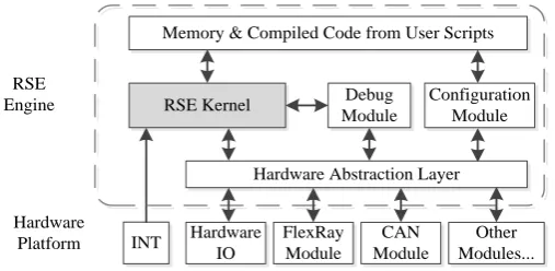
IO read and write and so on. RSE is made up of a collection of header and C source codes, and can be migrated into any hardware platform for real-time simulation, which requires only a small modification of the hardware low level interfacing functions. The developer can access not only the hardware resources, but also high-level scripts for the real-time simulation. The architecture of the RSE engine is shown in Fig. 2.
RSE Kernel Debug
Module
Configuration Module
Hardware Abstraction Layer Memory & Compiled Code from User Scripts
Hardware IO
FlexRay Module
CAN Module
Other Modules... INT
RSE Engine
Hardware Platform
Fig. 2. RSE engine architecture.
The RSE kernel is designed to be hardware independent, which only requires a memory buffer to run user scripts, this memory buffer is made up of three parts:
1) Execution memory, which contains the code compiled from user scripts;
2) Global memory, which contains all the global variables the script uses, and also constant variables; 3) Stack memory, which is managed by the RSE engine for internal function and API invoke.
The hardware abstraction layer translates communication requirements and IO commands into hardware operations.
2.
Implementation of the RSE Engine
The implementations of the real-time simulation engine includes the script based simulation language formulation, the script parser and compiler development, the configuration and debug module integration, API list, low-level drivers and script editing environment realization.
2.1.
Scripting Language Definition
To realize such a simulation environment the first step required is to define a proper scripting language for real-time control. Considering the portability, cross-platform ability, minimum memory consumption, and support for embedded system control such as Bit-wise operation, the C language template is chosen since it has good portability and is closeness to the machine.
The newly defined scripting language is called "RSE Language", where the most part of it is a subset of the standard C language, but it also has new features added such as CAN frame typed variable. Here the CAN feature is supported because an Automotive FlexRay network is a multi-bus environment, which includes not only FlexRay network, but also CAN, LIN, MOST and Ethernet bus systems. CAN bus is a subnet of FlexRay bus and should also be supported natively [6]. The RSE language is defined in the Backus-Naur Form (BNF), which is a notation used to describe context free grammars [7].
2.2.
Parser Creation
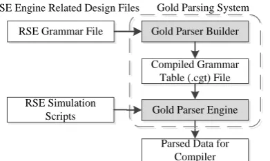
RSE Grammar File Gold Parser Builder
Compiled Grammar Table (.cgt) File
Gold Parser Engine RSE Simulation
Scripts
Parsed Data for Compiler RSE Engine Related Design Files Gold Parsing System
Fig. 3. RSE parser development using gold parsing engine.
In above all the steps, the most important one in the creation of the RSE parser is the design of the RSE grammar for the gold parser builder. This grammar file can be written using any text editor, which has to comply with the BNF syntax rules in the gold parsing system. Fig. 4 shows the grammar development inside the gold parser builder editor.
Fig. 4. The design of RSE language grammar file.
2.3.
The Design of the Compiler
To make RSE engine understand the purpose of the script, a compiler is needed to translate the scripts into binary stream that can be directly executed by the embedded system. Unlike compilers such as Win32, ARM and Motorola, the RSE compiler is platform independent, which generates intermediate code for the RSE engine low level APIs. RSE engine is API based, there are a total 60 basic APIs already implemented in the RSE engine kernel in embedded system, which support all the low level operations of the RSE language such as "Addition", "Subtraction", "If statement", "goto statement" and so on. Take one of the APIs "Addition" for example. Please see corresponding RSE script below:
y = x1 + x2 + x3
Such a piece of scripts will be automatically converted into two same API calls by the RSE engine, the name of these APIs are called "Addition", one API calculates "x1 + x2", generate result "x" and stores the result value "x" into internal stack, and the next one deals with "x + x3" and stores the result into the variable "y".
represents "x1" in the script, and "o2" represents "x2". "o1" and "o2" are popped from the internal stack managed by the RSE engine, after calculation, the result value will be pushed into the internal stack again for the next statement operation. So if the stack is properly managed by the engine, all the internal API can be directly and easily invoked.
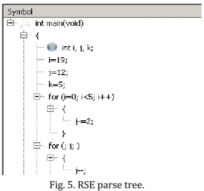
To properly manage the internal stack of the RSE engine, the compiler needs the parsed data structure generated by the RSE engine parser; this parsed data can be further generated into a complete parse tree by the RSE compiler. The parse tree is an ordered, rooted tree-like data structure that represents the syntactic structure of a string according to the grammar of the RSE language [9].
The RSE parse tree is built during the "reduction" stage when the simulation script is parsed by the RSE engine parser. The incoming reduced objects are pushed into a compiler stack when a statement is not completed, and popped from the compiler stack when a complete operation is identified by the compiler. Having all the reduced items in the parse tree, the logic of the user scripts are revealed by the compiler. Fig. 5 shows a parse tree generated by a piece of test codes, in which all the variable definitions, assignments, "if" statements, "for" statements and "while" statements are identified by the compiler.
Fig. 5. RSE parse tree.
The next step is to use the identified parse tree to form the final execution code, which is intermediate compared with the native binary code. A kind of data structure is proposed with the name "Execution Unit" for the execution code, which is the basic data structure that can be used by the low-level API of the hardware runtime environment. Each execution unit represents an atomic operation which is also known as the internal API mentioned above.
The compiler reads the parse tree from the very beginning, and generates execution units into a global memory buffer area called "execution memory".
Execution units are placed in an ordered sequence so that the RSE engine can find the next execution unit when the current one is performed. Fig. 6 shows an overview of the generated execution units after the parse tree has been built.
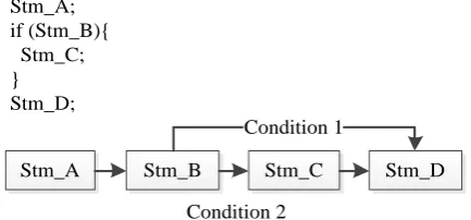
Until then, the whole parse tree has been generated into a flat memory area as execution units. Each execution unit has an execution pointer connecting to the next execution unit. Some execution units such as "for" or "while" have more execution pointers because they contain potential jumps that can link to other execution units. The RSE compiler is responsible for the correct linking of all the execution units. Fig. 7 demonstrates the linking of the execution units around the "If" statement.
Stm_C. Care should be taken to also make the execution pointer of Stm_C link to Stm_D, as to meet the requirements of the user logic.
Fig. 6. Execution units generated from the parse tree.
Stm_A Stm_A; if (Stm_B){ Stm_C; } Stm_D;
Stm_B Stm_C Stm_D
Condition 1
Condition 2
Fig. 7. The linking of execution units.
2.4.
RSE Execution Engine Design in the Embedded System
The RSE Execution Engine is designed to be platform independent, which is achieved by implementing kernel functions in pure C code and separating hardware specific functions with the engine functions by inserting a software layer called "Hardware Abstraction Layer".
There are four files required for the universal RSE engine in embedded systems:
2.4.1.
RSEInc.h
This is the platform switch option header file, which defines the capability including the stack size, global variable size and maximum execution unit count of the current RSE engine. By switching the compiler options of the endian mode, the RSE engine can be configured to accommodate different CPU models such as big-endian or small-endian.
2.4.2.
RSE.h
This is the main header file for data types and structure. Here the basic data type is declared including the 8-bit, 16-bit, 32-bit, 64-bit integer data types, IEEE 32-bit float and 64-bit double data types, and also CAN message data type defined in the RSE language. The data structure of RSE execution unit is also defined in this header, which contains the atomic operation type, parameter requirements and linking information with other execution units.
2.4.3.
RSEInternalFunctions.c
implemented, that support all the features of the RSE engine.
2.4.4.
RSESystemFunctions.c
This is the user API implementation unit. All the functions that can be invoked by the scripts are exported in this unit such as I/O operation, FlexRay frame transmission and reception. Interrupts such as timer interrupts and capture interrupts are also implemented inside this unit in order to ensure the real-time performance of the RSE engine.
2.5.
Configuration Module Realization
To make the RSE engine run with execution units, the next step is to download all the configuration data compiled by the RSE compiler from PC into the embedded system through USB interface. The data is represented by two kinds of memory: the execution units array and the initialization data of global variables, since the stack memory is allocated and managed by the engine itself in the embedded system, this kind of memory does not need to be downloaded.
As all the configuration data has been prepared, the RSE engine can be started from the entry point of the execution units. There are several entry points within an execution memory, which are defined by the RSE compiler from entry points of different functions during the compilation.
2.6.
Debug Module Integration
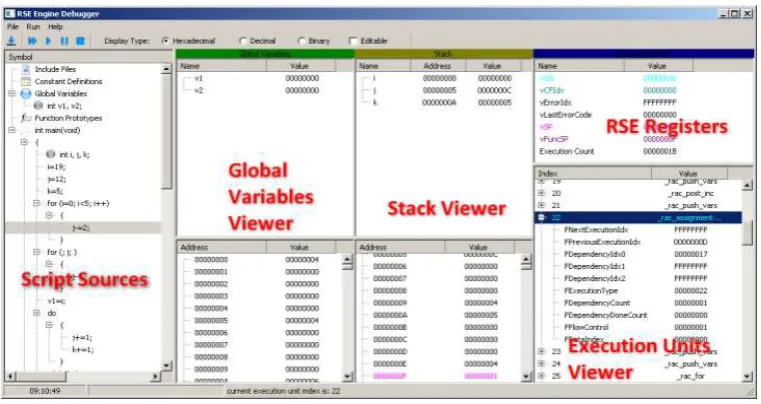
To ease the development process of the RSE engine, a RSE engine debugger is also created for the engine, which is running on windows platform on PC. As shown in Fig. 8.
Fig. 8. The RSE engine debugger.
The symbol tree on the left side is the script source viewer, where the users are able to find the script source written by them. Break points can be set on the source lines.
Global variables viewer displays all the global variables defined by the user script, and the stack viewer displays local variables inside the currently function being executed.
RSE Register window displays all the internal registers defined by the RSE engine. Unlike CPU registers, these registers are emulated including stack pointer, current function pointer, current execution unit pointer and so on.
2.7.
Simulation Engine Script API Realization
The Script API acts as a bridge to interconnect the hardware abstraction layer of RSE engine and the hardware components of the specific platform. Commands are translated from the hardware abstraction layer and the corresponding registers are set accordingly.
Take one of the API "int flexray_send_frame (const int ASlot, const unsigned char* AData, const int ASize);" for example, which updates the transmit buffer of FlexRay module and schedules the frame for the dedicated slot transmission. In the implementation area of this API function, the three input parameters are first popped from the RSE internal stack, and the parameter data is retrieved from the global memory and written into the registers of the FlexRay registers.
After all the needed APIs are created for the user scripts, user script is able to control most of the behavior of the current platform just like it is controlled by the native code. The time cost during script execution is a little bit longer than the native code due to additional time is required to analyze the intermediate code generated by the compiler by the RSE engine.
2.8.
FlexRay Low-Level Driver Development
As during the simulation, the FlexRay register values and parameters may be reloaded to adapt new network settings, a stand-alone FlexRay driver is needed for the simulation engine. Since FlexRay driver is also specific to platform, new driver should be generated for each migration of the dedicated platform.
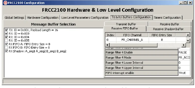
The FlexRay driver is responsible for FlexRay hardware module initialization, configuration, state management, interrupt handling, and also frame transmission and reception. Take one of the FlexRay driver implemented on Freescale MC9S12XF512 for example, which configures the Freescale FRCC2100 FlexRay core using the configuration generator as shown in Fig. 9.
Fig. 9. FlexRay configuration generator designed for Freescale FRCC2100.
This FlexRay driver configuration generator stores the generated configuration data into a memory area on the embedded system, which is loaded by the RSE engine API to configure the FlexRay hardware module. Due to the flexible configuration generation capability and the unlimited possibilities of the user simulation scripts, the difficulty of the FlexRay development is greatly reduced.
3.
Results and Analysis
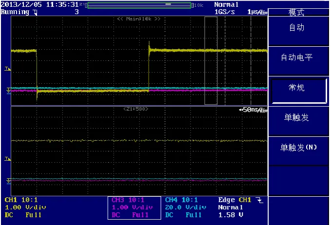
Take one of the implementations MC9S12XF512 as an example, the on-chip memory consumption of the RSE engine is about 20 KB and 16 KB flash memory is used for storing the RSE hardware driver and API implementation. Benchmark is also performed to validate the real-time performance of the RSE engine, the method of IO toggle measurement is used to measure the interrupt time overhead in the RSE script. A simple FlexRay receive interrupt costs about 4.3 micro-seconds for RSE processing, which is acceptable compared with the native code (about 1 micro-second), as shown in Fig. 10.
Fig. 10. Interrupt time overhead in RSE script.
Numerous simulation and test scripts are executed on all the platforms mentioned above and identical results are generated. Experiments prove the correct performance of the simulation engine even when executing complicated algorithms.
4.
Conclusion and Future Work
This paper demonstrates the development of the Real-Time simulation engine (RSE) implementation. The definition of the simulation language, the creation of the script parser and compiler, and the realization of the RSE kernel in embedded system along with the debugger and configuration module are introduced. Finally an experiment with RSE engine installed is executed for the validation of the features and engine performance. The advantages of this real-time simulation solution are concluded as below:
1) Execute c code directly in memory in real-time; 2) Support of single step debugging;
3) Error-free execution, support of memory bound check; 4) Safe, execution can be started or stopped at any time; 5) Easy and fast migration;
6) Execution speed higher than pure scripting language; 7) Light-weight, 16-bit micro-controller is also supported.
References
[1] Chaaban, K., & Leserf, P. (2009). Simulation of a steer-by-wire system using FlexRay-based ECU network. Proceedings of International Conference on Advances in Computational Tools for Engineering Applications (pp. 21-26).
[2] Schneider, R., Goswami, D., Zafar, S., & Chakraborty, S. (2011). Constraint-driven synthesis and tool-support for FlexRay-based automotive control systems. Proceedings of the 9th International
Conference on Hardware/Software Codesign and System Synthesis (pp. 139-148).
[3] Hagiescu, A., Bordoloi, U. D., Chakraborty, S., Sampath, P., et al. (2007). Performance analysis of FlexRay based ECU networks. Proceedings of the 44th Annual Design Automation Conference (pp. 284-289). [4] Stroop, J., & Stolpe, R. (2006). Prototyping of automotive control systems in a time-triggered
environment using FlexRay. Proceedings of the IEEE Conference on Computer Aided Control Systems
Design (pp. 2332-2337).
[5] Tian, G., Bai, P., & Chen, Q. (2008). Response time analysis of FlexRay communication in fuel cell hybrid vehicle. Proceedings of Vehicle Power and Propulsion Conference (pp. 1-4).
[6] Schmidt, E. G., Alkan, M., Schmidt, K., Yürüklü, E., & Karakaya, U. (2010). Performance evaluation of FlexRay/CAN networks interconnected by a gateway. Proceedings of International Symposium on
Industrial Embedded Systems (pp. 209-212).
[7] Garshol, L. M. (2005). EBNF: What are they and how do they work. Acedida Pela úLtima Vez Em, 16. [8] Kastner, W., & Kastner-Masilko, F. (2004). EDDL inside FDT/DTM. Proceedings of IEEE International
Workshop on Factory Communication Systems (pp. 365-368).
[9] Buehrer, G., Weide, B. W., & Sivilotti, P. A. G. (2005). Using parse tree validation to prevent SQL injection attacks. Proceedings of the Int. Workshop on Software Engineering and Middleware (pp. 106-113).
Chu Liu was born in Fujian, China in July 1985. He is now a PhD research student in Clean Energy Automotive Engineering Center of Tongji University in Shanghai, China. His major field of study is automotive network technology. He received his master’s degree in automotive engineering from Tongji University in Shanghai, China, 2011.
His research interests include automotive network communication, vehicle to vehicle communication, and intelligent vehicle.
Feng Luo received his PhD degree in aircraft control engineering from Northwestern Polytechnical University in 2000. From 2000 to 2002, he did his postdoctoral research work in the Department of Automotive Engineering of Tsinghua University. He joined Tongji University in 2002, he is now a professor in automotive engineering study of Tongji University.
His research interests include automotive networks, automotive electronic system control, and vehicle to vehicle communication.
Yunge Qu was born in Jilin, China in December 1988. She is now a master student in Tongji University in Shanghai, China. She received her bachelor’s degree in automation from Jilin University in 2012.