Instantaneous Power Controller Based
PSCPWM-Multilevel DSTATCOM Device For
Up-Gradation Of Power-Quality
J. Ganesh Prasad Reddy, Dr. K. Ramesh Reddy
Abstract: This paper presents the up-gradation of power quality with DSTATCOM connected in distribution system. The DSTATCOM employed for
power quality (change for the better) is a multi-level (5-level) cascaded H-Bridge configured device which is capable of delivering leveled compensating signals which are later filtered. The power switches of multi-level configured DSTATCOM are pulsed using multi-carrier PSCPWM fashion to which character reference components are obtained from instantaneous power control method. The proposed system is competent to make up unbalance, power factor and harmonics insisted by three-phase balanced non-linear loads and unbalanced non-linear load types in the distribution system.
Index Terms: DSTATCOM, Multilevel Inverter, Instantaneous Power Controller, Power-Quality Up-gradation, Phase-Shift PWM Scheme
————————————————————
1.
INTRODUCTION
Power delivery to the load point is expected to be utmost clear in nature with accuracy. Any deviation of power network parameters from the ideal form is annoyance in power system [1-5]. Poor power quality [6] makes system to experience stalled production, increased energy consumption, reduction in production pace, malfunctioning of equipment, reduced efficiency, reduction in life time of equipment. Presence of non-linear loads deteriorates power quality by inducing harmonics in source components. Harmonics are the waveforms having frequencies which are integral multiples of fundamental frequency. Non-linear loads when connected draw only non-linear components of currents from source components leaving out harmonic components at point of common coupling (PCC) [1-4]. This phenomenon disturbs or distorts the source currents and affects the other sensitive loads connected at PCC. Harmonic mitigation can be done through many ways. Passive filters with low circuit arrangement can mitigate harmonics. But passive filters can fix only fixed harmonics for which the particular passive filter is tuned leaving out remaining harmonics in the system. Also as order of harmonics is low, size of the passive filter increases as passive filter parameters are inversely proportional to tuned frequency [5-7]. This led to development of FACTS based devices for power quality improvement. DSTATCOM is one among FACTS controllers to improve power quality.
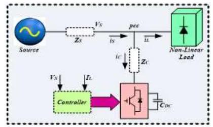
Figure 1: Block diagram of DSTATCOM in distribution system
The DSTATCOM connected in power distribution system is shown in figure 1. DSTATCOM is shunt compensator placed in parallel to distribution system. DSTATCOM is a voltage source converter inducing compensating currents to PCC (point of common coupling) for reducing harmonic effect. The paper presents IRP control [8] based PSCPWM-Multilevel DSTATCOM for power Quality Improvement. IRP control generates reference currents and pulse triggering to power switches of multi-level (CHB structure) DSTATCOM [9-10] is generated from multi-carrier PSCPWM pattern. Multi-level DSTATCOM in power distribution system is competent to make up unbalance, power factor and harmonics insisted by three-phase balanced linear loads and unbalanced non-linear load types in the distribution system.
2
PROPOSED
MULTILEVEL
DSTATCOM
Conventional (Square wave) inverters gives out square wave alternating output voltage consisting of high distortion. Alternating quantity with high distortion cannot be fed to any device and needs smoothing filters. Inverters are made up of capacitors and inductors which make the output current smooth as compared to switching square wave output we get with a conventional inverter. If the distortion quantity is high, filter size also increases. This phenomenon led to development of multi-level inverters.
————————————————
J. Ganesh Prasad Reddy, Research Scholar, Department of EEE,
JNTU Hyderabad, Hyderabad, Telangana, India, E-mail:
Dr. K. Ramesh Reddy, Principal, G. Narayanamma Institute of
Technology and Science for Women, Shaikpet, Hyderabad,
~ ~ ~ n isa isb isc Vsa Vsb Vsc Rnl Lnl i0 LINEAR LOAD Rlc Rlb Rla ilc Lla Llb Llc ila ilb NON-LINEAR LOAD N Cascaded H-Bridge Multi-Level DSTATCOM-VSI
ifa ifb ifc
PCC Ra+jXLa
Rb+jXLb
Rc+jXLc
F il te r I m p e d a n c e CDC Controller IL VS
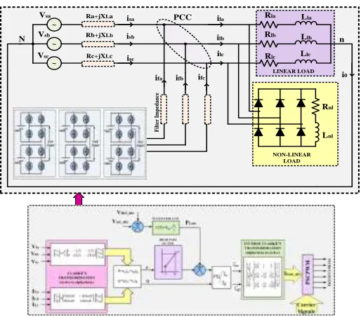
Figure 2: Multi-level DSTATCOM in power distribution system
Now-a-days multi-level inverters became the prior pick in many of the industries for high power high voltage applications. Multi-level inverters are able to generate high voltage with lower rated devices. Multi-level inverter generates leveled (stepped) output and as the number of level increases better output voltage waveform is obtained.
Phase-A Output
V
dcV
dcS
1S
2S
3S
4S
5S
6S
7S
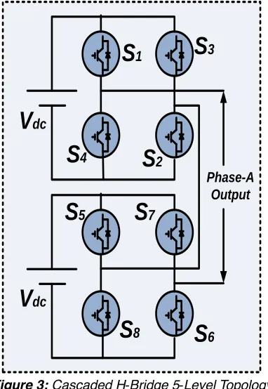
8Figure 3: Cascaded H-Bridge 5-Level Topology
Figure 2 illustrates multi-level DSTATCOM connected in power distribution system. Cascaded H-Bridge structure is employed to give out leveled output from VSI of DSTATCOM. Only one phase representation of cascaded H-Bridge multi-level inverter is shown. The cascaded H-bridge inverter has drawn tremendous interest due to the greater demand of medium-voltage high-power inverters. It is composed of multiple units of single-phase H-bridge power cells. The H-bridge cells are normally connected in cascade on their ac side to achieve medium voltage operation and low harmonic distortion. The cascaded H-bridge multilevel inverter requires a number of isolated dc supplies, each of which feeds H-bridge power cell. Figure 3 shows the structure of cascaded H-Bridge multi-level
inverter which gives 5-level output. 5-level structure contains two H-Bridge cells cascaded and each cell is driven with a DC-source. The respective switching operation of power switches of 5-level DSTATCOM with CHB structure is shown in table I.
3 PROPOSED
INSTANTANEOUS
POWER
CONTROLLER
The Instantaneous Real-Reactive Power (IRP) theory is first proposed by H. Akagi in the year of 1983. The formal IRP theory is most suitable for current compensation in a three phase power system using shunt-VSI structure and regulates DC-link voltage as a constant. The active-reactive power consignments are well with-in this orthogonal coordinated frame. The basic schematic view of formal IRP theory is depicted in Figure 4.
PI CONTROLLER
HIGH PASS
FILTER INVERSE CLARKE’S
TRANSFORMATION (alpha-beta to (a-b-c)
+ -+ CLARKE’S TRANSFORMATION
((a-b-c to alpha-beta)
P Q T O D S T A T C O M f f1 Carrier Signals PLoss ISact_abc VRef_abc Vact_abc Vta Vtc Vtb ILa ILc ILb P S C P W M PQ
Figure 4: IRP theory for DSTATCOM
Figure 5: PSCPWM pattern
A precise measurement of input variables are source voltage (Vsabc), load currents (ILabc) are fed to Clarke’s transformation
process. This process generates the voltage-current quantities in-terms of orthogonal coordinates (𝑉 , 𝐼 ).The instantaneous active (P) &reactive (Q) power quantities are calculated based on above specified coordinates by relevant equations. For attaining, this DC-link current of the shunt-VSI is differentiated with respect magnitude of desired current to peak harmonic current. The outcome error from this process is fed to PI controller for suppression of dominant error in PLoss.
The formation of reference current in orthogonal coordinate (Iα) is extracted by summation of active fundamental component and PLoss component. The terms 𝐼 are again
~ ~ ~ n isa isb isc Vsa Vsb Vsc Rnl Lnl i0 LINEAR LOAD Rlc Rlb Rla ilc Lla Llb Llc ila ilb NON-LINEAR LOAD N
Cascaded H-Bridge 5-Level DSTATCOM
ifa ifb ifc
PCC
Ra+jXLa
Rb+jXLb
Rc+jXLc
F il te r Im p ed a n ce
Figure 6: over-all diagram of Classic Instantaneous Real-Reactive Power (IRP) theory controlled 5-level DSTATCOM
The three phase source voltages and load currents are illustrated as below;
𝑣 = 𝑉𝑚 𝑠𝑖𝑛 (𝜔𝑡)
𝑣 = 𝑉𝑚 𝑠𝑖 𝑛 (𝜔𝑡 −2𝜋
3)
𝑣 = 𝑉𝑚 𝑠𝑖 𝑛 (𝜔𝑡 −
) (1)
𝑖 = ∑ 𝐼 sin (𝑛(𝜔𝑡) − 𝜃 )
𝑖 = ∑ 𝐼 sin (𝑛 (𝜔𝑡 −
2𝜋
3) − 𝜃 )
𝑖 = ∑ 𝐼 sin (𝑛 (𝜔𝑡 − ) − 𝜃 ) (2) The instantaneous vector coordinates, 𝑣 , 𝑖 are posed on
the axis-“a”, their magnitudes are varied of positive-negative ways with respective to the time and true for other phases. By using Park’s transformation process these phases are transforming to (α-β) coordinates, follows as;
*𝑣𝑣 + = √ [1 −1 2
⁄ −1⁄2
0 √3⁄2 − √3 2⁄ ] . [ 𝑣
𝑣 𝑣
] (3)
[𝑖𝑖 ] = √ [1 −1 2
⁄ −1⁄2
0 √3⁄2 − √3 2⁄ ] . [ 𝑖 𝑖 𝑖
] (4)
Where, (α-β) coordinates are orthogonal coordinates, the formal immediate power for three phase system can be illustrated as;
𝑝 = 𝑣 𝑖 + 𝑣 𝑖 (5) The formal active power equation is defined as;
𝑝 = 𝑣 . 𝑖 + 𝑣 . 𝑖 + 𝑣. 𝑖 (6) Relatively, the formal IRP theory is defined as;
𝑞 = −𝑣 𝑖 + 𝑣 𝑖 (7) Although, the instantaneous real-reactive power is illustrated in matrix form as;
*𝑝𝑞+ = *−𝑣𝑣 𝑣𝑣 + [𝑖𝑖 ] (8)
The (α-β) current components can be acquired as;
[𝑖𝑖 ] =
*
𝑣 𝑣
−𝑣 𝑣 + *
𝑝
𝑞+ (9)
Where,
= 𝑣 + 𝑣 (10) The instantaneous real power(𝑝), reactive power (𝑞) can be degraded into oscillatory and DC average components and are expressed as,
𝑝 = 𝑝̅ + 𝑝̃
𝑞 = 𝑞̅ + 𝑞̃ (11) Where, 𝑝̅ 𝑎𝑛𝑑 𝑞̅ - DC average part, and𝑝̃, 𝑞̃- AC oscillatory part of intended theory and the oscillatory quantity of instantaneous real power. Although, the reference supply currents 𝑖 and 𝑖
into (α-β) coordinates can be evaluated as;
[𝑖𝑖
] =
1
*𝑣𝑣 −𝑣𝑣 + *𝑝𝑞+
These reference currents are transformed to a-b-c components using Inverse transformation process as;
[ 𝑖 𝑖 𝑖 ] = √ [ 1 √2
⁄ 1 0
1 √2
⁄ −1⁄2 √3⁄2
1 √2
⁄ −1⁄2 − √3 2⁄
] [
𝑖 𝑖
𝑖
] (12)
Where, 𝑖 is represented as the zero-sequence current component, which should be zero in three-wire three-phase system. The reference currents are overlapped to carrier signals to generate pulses. Multi-carrier phase-shifted PWM pattern is employed to produce triggering pulses to power switches of 5-level DSTATCOM. The reference voltage is continuously compared with each of the shifted carrier signals. Each cell is modulated independently using the PWM, which provides an even power distribution among the cells. A carrier phase is shifted for the cascaded inverter is introduced across the cells to generate a stepped multilevel output waveform with lower distortion. PSCPWM pattern to produce triggering pulses is shown in figure 5. The over-all diagram of Instantaneous Real-Reactive Power (IRP) theory controlled 5-level DSTATCOM Model is illustrated in Figure 6.
4 MATLAB/SIMULINK
RESULTS
The performance of proposed instantaneous power controller based Five-Level DSTATCOM topology is verified under balanced and un-balanced non-linear load conditions by using Matlab/Simulink platform. Table II shows the system parameters of model. The system parameters are illustrated in Table.2.
Table.2 System Parameters
Parameter Value
Source Voltage 11 KV, 50 Hz Source Impedance 0.1 Ohms, 0.9 mH DC Link Capacitance 1550 µF
Filter Impedance 0.001 Ohms, 0.9 mH Carrier signal frequency 3960 Hz
4.1 Under Balanced Non-Linear Load
Figure 7: Source Voltage
Figure 7 shows three-phase source voltage of distribution system. Three phases of voltage signal are with constant peak and sinusoidal in shape.
Figure 8: Source current
Figure 8 shows the three-phase source currents of distribution system with balanced non-linear load. The load is increased at time instant 0.3 sec and restored to previous load at 0.4 sec. The source current also increases to feed increased load from 0.3 to 0.4 seconds.
Figure 9: Load voltage
Figure 9 shows three-phase load voltage of system with balanced non-linear load. Though, the non-linear load is increased from 0.3 to 0.4 seconds, the load voltage remains with constant peak.
Figure 10: Load current
Figure 10 shows three-phase load currents in distribution system with balanced non-linear load. Load increases from 0.3 sec to 0.4 sec and hence load current raises during that duration.
Figure 11: Source Active and reactive powers
Figure 11 shows the active and reactive power fed from source. During load increased time, active power is also increased to meet load demand. Reactive power almost remains zero irrespective of the system conditions.
Figure 12: Load active and reactive powers
Figure 13: Compensating currents from DSTATCOM
Figure 13 shows three-phase compensating currents fed from DSTATCOM to PCC to minimize the effect of harmonics in distribution system.
Figure 14: source power factor
Figure 14 shows source power factor. The angle between source voltage and source current is almost zero and cosine of angle (power factor) in source tends to unity. Source current is gained with value for better appearance.
Figure 15: Load power factor
Figure 15 shows load power factor. The angle between load voltage and load current is very large and cosine of angle (power factor) in load tends decrease far below unity. Load current is gained with value for better appearance.
Figure 16: 5-level output of multi-level DSTATCOM
Figure 16 shows 5-level output of multi-level DSTATCOM. Leveled output voltage of DSTATCOM in three phases is shown.
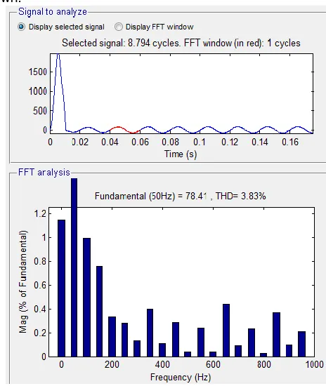
Figure 18: THD in load current
Figure 17 shows THD FFT window of source current. Source current is distorted by 3.83% and is par within nominal limit. Load is of non-linear type and is distorted by 30.10% as shown in figure 18.
4.1 Under Un-Balanced Non-Linear Load
Figure 19: Source Voltage
Figure 19 shows three-phase source voltage of distribution system. Three phases of voltage signal are with constant peak and sinusoidal in shape.
Figure 20: Source current
Figure 20 shows the three-phase source currents of distribution system with un-balanced non-linear load. The load is increased from 100A to 150A at time instant 0.2 sec and restored to 100A load at 0.3 sec and from time instant 0.4 to 0.5 sec. The source current also increases to feed increased load from 0.2 to 0.3 seconds and 0.4 to 0.5 sec.
Figure 21: Load voltage
Figure 21 shows three-phase load voltage of system with un-balanced non-linear load. Though, the non-linear load is increased from 0.3 to 0.4 seconds and 0.4 to 0.5 sec, the load voltage remains with constant peak.
Figure 22: Load current
Figure 22 shows three-phase load currents in distribution system with un-balanced non-linear load. Load increases from 0.2 sec to 0.3 sec and also during 0.4 to 0.5 sec and hence load current raises during that particular duration.
Figure 23: Source Active and reactive powers
source. During load increased time, active power is also increased to meet load demand. Reactive power almost remains zero irrespective of the system conditions.
Figure 24: Load active and reactive powers
Figure 24 shows the active and reactive power of load. During load increased time 0.2 to 0.3 sec and 0.4 to 0.5 sec, active power is also increased according to load demand. Reactive power almost remains constant irrespective of the system conditions apart from slight fluctuations at load change time.
Figure 25: Compensating currents from DSTATCOM
Figure 25 shows three-phase compensating currents fed from DSTATCOM to PCC to minimize the effect of harmonics in distribution system.
Figure 26: source power factor
Figure 26 shows source power factor. The angle between
source voltage and source current is almost zero and cosine of angle (power factor) in source tends to unity. Source current is gained with value for better appearance.
Figure 27: Load power factor
Figure 27 shows load power factor. The angle between load voltage and load current is very large and cosine of angle (power factor) in load tends decrease far below unity. Load current is gained with value for better appearance.
Figure 28: 5-level output of multi-level DSTATCOM
Figure 29: THD in source current
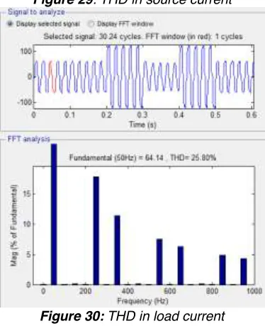
Figure 30: THD in load current
Figure 29 shows THD FFT window of source current. Source current is distorted by 2.86% and is par within nominal limit. Load is of non-linear type and is distorted by 25.80% as shown in figure 30. Table.3 illustrates the comparison of harmonic distortion analysis in different loading conditions of distribution system. In both the loading conditions of distribution system, source current distortion is limited below 5% (nominal value).
Table.3 THD comparison
THD Balanced
Non-Linear load
Un-balanced Non-Linear load Source Current 3.83 % 2.86 % Load Current 30.10 % 25.80 %
5 CONCLUSION
Harmonics in power distribution system effects the other sensitive loads connected at point of common coupling. Limitation of harmonics using FACTS based controllers are in practice. This paper presents five-level DSTATCOM for compensating harmonic effect in distribution system. Reference currents to control DSTATCOM are generated from IRP theory. IRP theory is explained in detail. Triggering pulses to DSTATCOM switches are generated from PSCPWM pattern of multi-carrier technique. The system with 5-level DSTATCOM for power quality improvement is validated with different loading conditions. In both the loading conditions of distribution system, source current distortion is limited below 5% (nominal value) with multi-level DSTATCOM in operation. Harmonic analysis presented in table illustrates multi-level DSTATCOM effectively limits the harmonics in source components of distribution system.
REFERENCES
[1] V. Khadkikar "Enhancing electric power quality using UPQC: A comprehensive overview" IEEE Trans. Power Electron. vol. 27 no. 5 pp. 2284-2297 2012.
[2] A. Luo H. Xiao F. Ma et al. "Distribution static compensator based on an improved direct power control
strategy" IET Power Electron. vol. 7 no. 4 pp. 957-964 2014.
[3] C. Kumar M.K. Mishra "An improved hybrid DSTATCOM topology to compensate reactive and nonlinear loads" IEEE Trans. Ind. Electron. vol. 61 no. 12 pp. 6517-6527 2014.
[4] R. Kalpana, S. C. Khimavath, S. P. P and B. Singh, "Power Quality Enhancement Using Current Injection Technique in a Zigzag Configured Autotransformer Based 12-Pulse Rectifier," in IEEE Transactions on Industry Applications, 2018 (early access).
[5] T. Zaveri B. Bhalja N. Zaveri "Comparison of control strategies for DSTATCOM in three-phase four-wire distribution system for power quality improvement under various source voltage and load conditions" Electr. Power Energy Syst. vol. 43 pp. 582-594 2012.
[6] A. A. Patel and A. A. Patel, "Application of DSTATCOM for harmonics elimination and power quality improvement," 2017 International Conference on Energy, Communication, Data Analytics and Soft Computing (ICECDS), Chennai, India, 2017, pp. 3007-3011.
[7] G. Mallesham and C. S. Kumar, "Enhancement of power quality using UPQC for hybrid PEMFC and DFIG based wind energy system connected to weak grid," 2017 International Conference on Technological Advancements in Power and Energy ( TAP Energy), Kollam, India, 2017, pp. 1-6.
[8] M. Pradhan and M. K. Mishra, "Dual P-Q Theory based Energy Optimized Dynamic Voltage Restorer for Power Quality Improvement in Distribution System," in IEEE Transactions on Industrial Electronics, 2018 (early access).
[9] Y. R. Ashtekar, A. A. Mude and S. A. Khubalkar, "Power quality improvement by using modular multilevel cascade converter based STATCOM," 2018 2nd International Conference on Inventive Systems and Control (ICISC), Coimbatore, India, 2018, pp. 169-173.
[10]T. S. Saggu, L. Singh and B. Gill, "Harmonics Mitigation in a Steel Industry Using 11-Level Cascaded Multilevel Inverter-Based DSTATCOM," in Canadian Journal of Electrical and Computer Engineering, vol. 40, no. 2, pp.