A Novel Design And Simulation Of U-Shaped
Microstrip Patch Antenna For Future 5G Mobile
Communication
Sathuluri Mallikharjuna Rao, Jaya Apurvarani, Valle.Kavya, Sirisha.Yandapalli
Abstract: This paper presents a novel millimeter wave u-shaped micro strip patch antenna for impending 5G mobile communication technology at centralized frequencies 24.6GHz and 41.1GHz with bandwidth 1.1GHz and 5GHz respectively which constitutes an economical substrate with a minuscule sized radiating element mounted on the top it which is admissible for portable devices. It constitutes rogers RT(5880)/Duroid which is a lossy substrate whose dielectric constant is 2.2 with a loss tangent of 0.0004 and 0.508 being it‟s standard thickness value for the radiating element and ground plane idealized material is used. The dimensions of the dielectric material are 7.3mmx8.5mmx1mm and for the ground plane it is 7.3mmx8.5mm.The area of the radiating element is 9.30 .Even an array which constitutes „2‟ u shaped patches has been proposed in order to achieve high gain. The dimensions of the substrate is 8.75mmx9.88mmx0.8mm and for the ground plane is 8.75mmx9.8mm.The area of an individual element in an array is 7.50 .As a step further this paper even presents a 6G U-shaped millimeter wave micro strip patch antenna whose centralized frequencies are 100.9GHz and 189.4GHz.The dimensions of the dielectric material is 2.15mmx1.75x0.3mm.The area of the radiating element is 0.65 A simple transmission line feeding technique i.e. micro strip is used. The comprehensive size of the antenna is 7.3mmx8.5mmx1mm.ANSYS HFSS software is used to simulate the results of the proposed antenna.
Keywords: U-shaped antenna, U-shaped array, U-shaped 5G antenna.
————————————————————
1. INTRODUCTION
The millimeter wave bands have obtained a wide range of research in recent times due to the availability of ultra broad spectrum bands in various application in domains especially in mobile communications. During the past decades wireless cellular networks development has been flourishing briskly applications such as smart phone, tablets and video streaming have lofty insistence for high quality data communications. The cellular networks capacity in 2020 is envisaged to be as much as 1000 times juxtaposed to contemporary fourth generation (4G) technology. Mean time the cellular network is awaited to be capable of connecting 50 billion devices for wireless services. Typically mm wave frequencies range from 6GHz to 100GHz including 6GHz,15GHz,28GHz,38GHz,60GHz and E-band(71-76GHz,81-86GHz)[1]. The enormous majority of communication systems operates at frequencies < 3GHz,the available spectrum is becoming scant, especially at the microwave bands. Therefore ,it is necessary to operate at millimeter wave bands as it has a broad unexploited spectrum which ranges from 20GHz to 90GHz.[2]. 5G abbreviates 5th generation wireless system .It indicates the anticipated phase of the mobile telecommunication which is far beyond the contemporary 4G standards whose throughput speed is 1Gbps and the speed of connectivity is 25Mbps is expected[3].5G accommodates different types of networks where as 6G aggregates them dynamically. The frequency band for 6G is allocated by the federal communication commission which is from 95GHz to 3THz that aren‟t currently being used in any consumer electronic devices and posses wider bandwidth with vast potential for data streaming. Now-a-days the fabrication of antenna‟s are done by the commercially available substrates for operating frequencies beyond 10GHz. [4], where as Rogers RT/Duroid 5880 is an exceptional case. Rogers substrate has high tensile strength value and water absorption values. It has the lowest electric loss which gives excellent return loss and bandwidth values, and also the lowest
greater than 93%.In reference paper [13], a low complexity metallic tapered slot antenna (TSA) array for millimeter wave multi beam massive MIMO communication, whose reflection coefficient is less than -15dB voltage standing wave ratio (VSWR<1.5)within the frequency range from 22.5-32GHz and the gain of the antenna element varies from 8.2-9.6dB over the frequency range of 24-32GHz. In reference paper[14] a millimeter wave micro strip array with 4 elements, with 4mm spacing has been proposed to achieve 12dB gain at 38.6GHz,47.7GHz and 54.3GHz having bandwidth 3.5GHz,2.5GHz and 1.3GHz respectively with tapered line feeding was designed. The proposed U-shaped array antenna has 2 elements whose centralized frequencies are 38.8GHz and 47GHz which has higher bandwidths, lower insertion loss, very low reflection coefficient which is return loss (expressed in dB). The following tables constitutes the comparison of the various radiation parameter with the related work and the proposed design of the5G U-shaped antenna in table 1 and for the 5G U-shaped array in table2 and for the 6G U-shaped antenna in table 1.
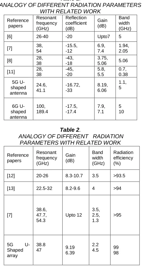
Table 1.
ANALOGY OF DIFFERENT RADIATION PARAMETERS WITH RELATED WORK
Reference papers Resonant frequency (GHz) Reflection coefficient (dB) Gain (dB) Band width (GHz)
[6] 26-40 -20 Upto7 5
[7] 38,
54 -15.5, -12 6.9, 7.4 1.94, 2.05
[8] 28,
38
-43, -18
3.75,
5.06 5.06
[11] 28, 38 -45, -20 5.8, 5.5 0.7, 0.38 5G U-shaped antenna 24.6, 41.1 -16.72, -33 8.19, 6.06 1.1, 5 6G U-shaped antenna 100, 189.4 -17.5, -17.4 7.9, 7.1 5 10
Table 2.
ANALOGY OF DIFFERENT RADIATION PARAMETERS WITH RELATED WORK
Reference papers Resonant frequency (GHz) Gain (dB) Band width (GHz) Radiation efficiency (%)
[12] 20-26 8.3-10.7 3.5 >93.5
[13] 22.5-32 8.2-9.6 4 >94
[7] 38.6, 47.7, 54.3 Upto 12 3.5, 2.5, 1.3 >95
5G U-Shaped array
38.8
47 9.19
6.39
2.2
4.5 99 98
2. ANTENNA DESIGN
2.1 Dielectric material analysis:
In micro strip patch antenna the dielectric material is used in order to provide both electrical and mechanical support. Dielectric constant is the parameter which defines the storage capacity of the electrical energy in an electrical field of a dielectric material. In this work as the antenna is designed to operate at millimeter wave frequencies loss tangent value plays a key role as these frequencies are prone to insertion losses, dissipation losses. The loss tangent value for FR4 glass epoxy is 0.013which is far greater than that of RT Duroid i,e 0.0004 the water absorption coefficient is less for RT Duroid i,e.0.02% where as for the FR4 glass epoxy is 0.25%.Hence RT Duroid is used for this antenna.
2.2:Feeding techinique analysis:
There are several feeding techniques are available for microstrip patch antennas among them the non contact feeding techniques i,e. aperture couple feed and proximity coupled feed are known to have minimum spurious feed radiation but the fabrication is very difficult. The coaxial line feed and the microstrip line feed are contact feeding techniques which are widely used. In coaxial line feed the reliability and fabrication is difficult due to soldering. The microstrip line feeding technique is the simplest one which is apt for mm wave frequencies .Even the coplanar wave guide is not suitable for these mm frequencies
2.3Structral analysis:
In this work, the shape of the radiating element is U-shaped not an elementary rectangular patch .The patch is positioned at the center of the antenna such that the extension length requirements are met in order to reduce the effects due to the fringing fields. The dimensional requirement of the U-shaped patch is met with respect to the dimensions calculated using design equations at the desired operating frequency. The area of the U-shaped patch is equivalent to the area of the rectangular patch which I calculated using the design equations at the desired operating frequency.
2.4 5G mm wave U-shaped antenna design:
Fig 1: Geometry of proposed 5G U-shaped microstrip feed antenna
2.5 5G mm wave array antenna design:
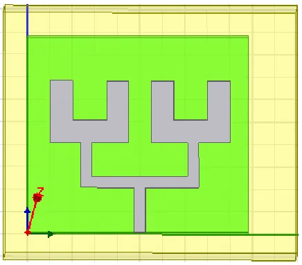
As shown in the fig.2, U-shaped microstrip patch array is designed whose substrate dimensions are 8.75x9.8x0.8mm and the material Rogers RT 5880 is used which has a dielectric constant of 2.2 and 0.0013 loss tangent .The ground plane dimensions are same as that of the substrate‟s i.e. 8.75x9.8mm.The area of the individual element in an array is 7.50 . Transmission line feeding technique is used whose length is 2.1mm and it‟s width is 0.5mm.
Fig 2: Geometry of U-shaped microstrip array antenna 2.6 6G mm wave U-shaped antenna design:
As shown in fig.3 microstrip patch antenna is designed for impending 6G communication whose substrate dimensions are Ls x Ws and the material rogers RT5880 is used which has 2.2 dielectric constant and 0.0013 loss tangent, standard height of the substrate i.e. 0.508mm is used. The dimensions for substrate is 2.15x1.75x0.3mm.The ground plane dimensions i.e. length and width is same as that of the dielectric material substrate i.e. 2.15mmx1.75mm, except for the height which exists only for the substrate. The transmission line feeding technique which is microstrip line feed is used to design the microstrip patch antenna
which is proposed in this paper. Whose dimensions are 0.5mmx0.2mm.The radiating element area is 0.65 .
Fig 3: Geometry of proposed 6G U-shaped microstrip feed antenna
3. SIMULATION RESULTS
3.1.Return loss plot:
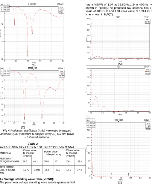
Return loss is the loss of power in the signal returned/reflected by a discontinuity in a transmission line.S-parameter‟S1‟ represents how much power is reflected from the antenna and hence it is known return loss or reflection coefficient. If S11=0dB then the delivered power gets reflected back from the antenna and therefore nothing is radiated. If S11=-10dB, then the antenna receives 3dB amount of power perfectly and the remaining amount of power i.e.-7dB is reflected back, therefore the desired value of S11 should be less than -10dB, for the antenna to perform effectively. The proposed antenna has the reflection coefficient of 16.7dB at 24.6GHz and -33.08dB at 41.1GHz which is shown in figure.4(a).and the array has a good reflection coefficient value at the frequency 38.8GHz which is 35.6dB,and at 47GHz it is -20.9dB as shown in figure 4(b).The proposed 6G antenna has the reflection coefficient of 17.5dB at 100GHz and -17.4dB at 189.4GHz which is shown in figure4(c).
(B)
(C)
Fig 4:Reflection coefficient (A)5G mm wave U-shaped antenna(B)5G mm wave U-shaped array (C) 6G mm wave
U-shaped antenna
Table 3.
REFLECTION COEFFICIENT OF PROPOSED ANTENNA
ANTENNA
5G mm wave U-shaped Antenna
5Gmm wave U-shaped array
6G mm wave U-shaped Antenna RESONANT
FREQUENCY(GH z)
24.6 41.1 38.8 47 100 189.4
REFLECTION COEFFICIENT (dB)
-16.72 -33.08 -35.6 -20.9 -17.5 -17.4
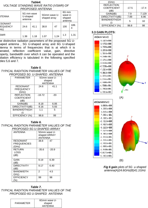
3.2 Voltage standing wave ratio (VSWR):
The parameter voltage standing wave ratio is quintessential parameter which numerically determines how much perfectly the antenna is impedance matched to the transmission line to which it is connected to. VSWR is always positive real number which determines the performance of the antenna, the smaller it is the better the performance of the antenna.The proposed 5G antenna has 1.38 VSWR value at 24.6GHz and 1.18vswr value at 41.1GHz which is as shown in fig.5(A).Where as the array
has a VSWR of 1.07 at 38.8GHz,1.24at 47GHz which is shown in fig5(B).The proposed 6G antenna has 1.3 vswr value at 100 GHz and 1.31 vswr value at 189.4 GHz which is as shown in fig5(C).
(A)
(B)
(C)
Fig 5: voltage standing wave ratio (VSWR):(a)5Gmm wave U-shaped antenna(b)5Gmm wave U-shaped array.(c)
Table4.
VOLTAGE STANDING WAVE RATIO (VSWR) OF PROPOSED ANTENNA
ANTENNA
5G mm wave U-shaped antenna
5Gmm wave U-shaped array 6G mm wave U-shaped antenna RESONANT FREQUENCY (GHz)
24.6 41.1 38.8 47 100 189. 4
VSWR
1.38 1.18 1.07 1.24 1.3 1.31
The distinctive radiation parameters of the proposed 5G U-shaped antenna , 5G U-U-shaped array and 6G U-U-shaped antenna in terms of frequencies that is at which it is operated, reflection coefficient value, gain, directive property, bandwidth over which it can be operated and the radiation efficiency is tabulated in the following specified tables 5,6 and 7.
Table 5.
TYPICAL RADITION PARAMETER VALUES OF THE PROPOSED 5G U-SHAPED ANTENNA
PARAMETER 5Gmm wave U-shaped ANTENNA RESONANT
FREQUENCY (GHz)
24.6 41.1
REFLECTION COEFFICIENT
(dB)
-16.72 -33
GAIN(dB) 8.18 6.06 DIRECTIVITY(dB) 8.16 5.93 BANDWIDTH(GH
z)
1.1 5
EFFICIENCY (%) 98.8 99
Table 6.
TYPICAL RADITION PARAMETER VALUES OF THE PROPOSED 5G U-SHAPED ARRAY
ANTENNA 5Gmm wave U-shaped ARRAY ANTENNA RESONANT
FREQUENCIES (GHz)
38.8 47
RETURN LOSS (dB)
-35.6 -20.9
GAIN (dB)
9.19 6.39
DIRECTIVITY (dB)
9.17 6.40
BANDWIDTH GHz)
2 4.5
EFFICIENCY (%)
99 98
Table 7.
TYPICAL RADITION PARAMETER VALUES OF THE PROPOSED 6G U-SHAPED ANTENNA
PARAMETER
6Gmm wave U-shaped ANTENNA RESONANT
100 189.4
(GHz) REFLECTION COEFFICIENT
(dB)
-17.5 -17.4
GAIN(dB) 7.9 7.129 DIRECTIVITY(dB) 7.89 6.96 BANDWIDTH(GH
z) 5 10
EFFICIENCY (%) 98.8 98
3.3 GAIN PLOTS:
(A)
(B)
(A)
(B)
Fig 7. gain plots of u-shaped array antenna (A) 38.8GHz(B)47GHz
(A)
(B)
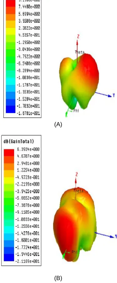
Fig 8.gain plots of 6G u-shaped antenna(A)100GHz(B)189.4GHz
3.4 DIRECTIVITY PLOTS:
(A)
(B)
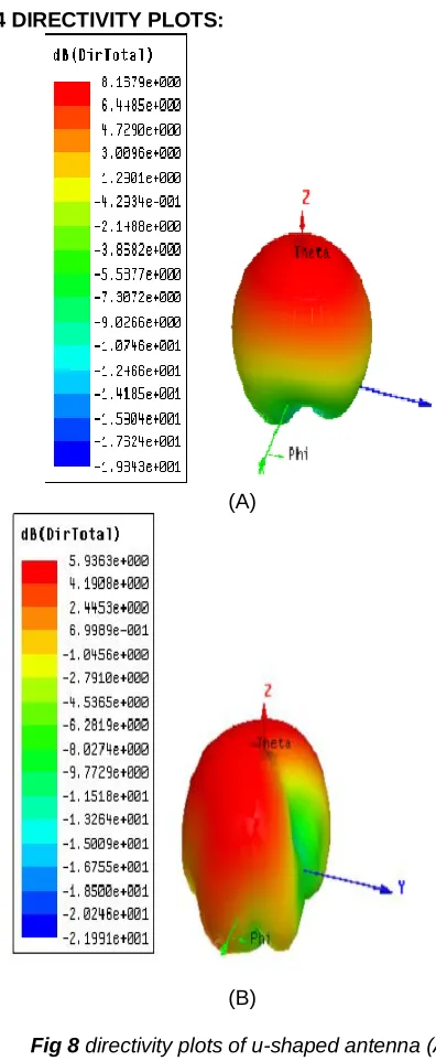
Fig 8 directivity plots of u-shaped antenna (A) 24.6GHz(B)41.1GHz
(A)
(B)
(A)
(B)
Fig 10 directivity plots of u-shaped antenna (A) 100GHz(B)189.4GHz
3.5 RADIATION PLOTS:
(A)
(B)
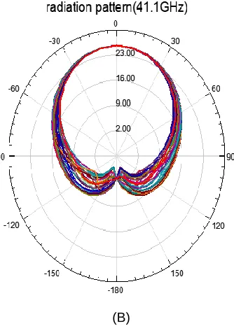
Fig 11 radiation pattern plots of u-shaped antenna (A )24.6GHz (B)41.1GHz
(B)
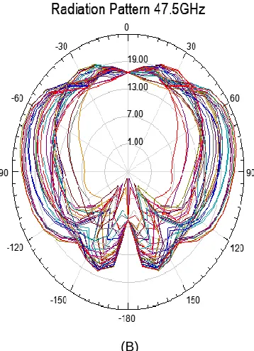
Fig 12 radiation pattern plots of u-shaped array antenna(A)38.8GHz(B)47GHz
(A)
(B)
Fig 13 radiation pattern plots of u-shaped antenna (A )24.6GHz (B)41.1GHz
4.CONCLUSION
In this research, an elementary-shaped microstrip patch antenna has been proposed for 5G wireless communication. The proposed antenna yields dual band. U-shaped microstrip patch antenna provides 24.6GHz and 41.1GHz frequencies which are going to be used for 5G mobile communication. It yields a gain of 8.19dB and 6.06dB at the centralized frequencies 24.6GHz and 41.1GHz.This shows that designing an array at these frequencies increments the gain and bandwidth parameters. Here, in this paper a 2-U-shaped linear array is employed, which gives a high radiation efficiency, lower insertion losses, very low return loss ,high gain and directive pattern. The proposed antenna has high gain, bandwidth, outstanding radiation efficiency and directivity as shown in tables, which proves that this antenna is just perfect for 5G mobile communication but the radiation parameters can further be improved. Even the much-awaited 6G antenna is also proposed. .
5. REFERENCES
[1] Wei,Xiang,kan,Zeng,Xuemin(Shetman),Shen “5G Mobile communications” in 2017, Springer, cham, ISBN-978-3-319-34208-5.
[2] Jeffrey G.Andrews, Stefano Buzzi,Wan choi,Stephen Hanly.Angel Lozano, Anthony C.K. Soong,Jianzhong Charlie Zhang “what will 5G Be ?”,12 May 2014,IEEE JSAC Special Issue on 5G wireless communication systems.
[3] Kumar Goswami,,kamini sahu, abhay shukla,
”upcoming Technologies:5G and
6G”,IJSR,ISSN(online):2319-7064,2013.
[4] David Alvarez Outerelo; Ana Vazwuez Alejos; Manuel Garcia Sanchez; Maria Vera Isasa, “Microstrip Antenna for 5g Broad band communication: Over view of Design Issues ”, in 2015 IEEE international symposium on antennas and propagation & USNC/URSI National Radio Science Meeting,2015, pp.2443-2444.
[5] Anzar khan, Rajesh Nema, “Analysis of five different
substrates on Microstrip Patch
Antenna”,2012,International journal of Computer Applications.
[6] Constantine A.Balanis “Antenna theory Analysis and Design” In 2015 WILEY-Third edition ISBN: 978-81-265-2422-8.
[7] Syeda fizzah Jilani,Qammer H.Abbasi,Akram Alomainy;“Ink-jet Printed Millimeter wave PET-based flexible antenna for 5G wireless Application”,2018.IEEE MT-S International Microwave workshop services on 5G Hardware and system Technologies (IMWS-5G). [8] D.Imran, M.M.Farooqi, M.I.Khattak, Z.Ullah, M.I.Khan,
and H.Dar “Millimeter wave Microstrip Patch Antenna for 5G Monile Communication” 2018 Symposium on Antennas and Propagation (APSURSI), Fajardo, PR, USA, 2016, pp.393-394.
Conference on micro waves for Intelligent Mobility (ICMIM), 2017, pp.21-24.
[10] Prithu Rouy; R.K,Vishwakakarma; Akshay Jain;Rashimi Singh, “Multi band milli meter wave antenna array for 5G communication”, in 22016 International Conference on Emerging Trends in Electrical Electronics & Sustainable Energy Systems(ICETEESES), 2016, PP.102-105.
[11] Joti Saini; S.K.Agarwal “Design a single band microstrip patch antenna at 60GHz millimeter wave for 5G applications” in 2017international Conference on Computer, Communications and Electronics (Comptelax) IEEE Conference Publications, Pages (227-230)
[12] .Y.A.M.K.Hashem; O.M.Haraz and E.D.M. El-Sayed, “6-Element 28/38GHz dual-band MIMO PIFA for Future 5G cellular systems”, 2016IEEE Interntional Symposium on Antennas and Propagation (APSURSI), Fajardo, PR, USA, 2016, pp.393-394.
[13] Ramadan A.Alhalabi,Gabriel M.Rbeiz” High efficiency angled dipole antennas for mm wave phased array applications” in 2008 IEEE Transactions on Antennas and propagation