Centre
of
Excellence
for
Nuclear
Materials
Workshop
Materials
Innovation
for
Nuclear Optimized
Systems
December 5-7, 2012, CEA – INSTN Saclay, France
Hélène BURLET
CEA (France)
Mechanical and Thermal Resistance of Multi-Material
Components for ITER
Workshop
organized
by:
Christophe
GALLÉ,
CEA/MINOS,
Saclay
–
[email protected]
Constantin
MEIS,
CEA/INSTN,
Saclay
–
[email protected]
Workshop
Materials
Innovation
for
Nuclear
Optimized
Systems
December 5-7, 2012, CEA – INSTN Saclay, France
Mechanical and Thermal Resistance of Multi-Material
Components for ITER
Hélène BURLET
11
CEA-DEN-DRT, Laboratoires d’Innovation pour les Technologies des Energies, LITEN (Grenoble, France)
The First Wall panels for ITER are complex parts composed of stainless steel, copper and beryllium [1]. These materials are joined using diffusion bonding technique. The stainless steel is a commonly used in nuclear reactors 316LN material and acts as a structural material. The copper alloy is a CuCrZr material which acts as a heat sink. The beryllium consisting in tiles and layer is used as the protective plasma facing material.
The fabrication of these panels is performed through 2 main steps. The first step consists in welding all together a bi-metallic support structure made from a thick CuCrZr plate embedded with 316LN tubes and bonded to a thick 316LN backing plate with cooling channels. The bonding is performed in a HIP (Hot Isostatic Pressure) facility. The second step is performed at a lower temperature and aims at simultaneously welding by HIP Be onto CuCrZr and ageing the CuCrZr heat sink to obtain the correct mechanical resistance of this alloy reinforced by precipitates.
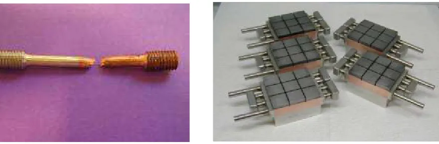
The various joints 316LN/316LN, 316LN/CuCrZr, and CuCrZr/Be are then characterized [2] from a microstructural point of view and by mechanical tests. It is quite hard to characterize the strength of a diffusion bonded joints. Standard tests may be used for homogeneous joints whereas specific tests have been developed to characterize the heterogeneous bonds. To optimize the bond, we performed mainly impact and tensile bimaterial tests (Fig 1). Once the manufacture parameters have been optimized, advanced mechanical tests are performed based on Bimetallic CT specimens, axisymmetric notched specimens, 4P bending specimens. Numerical simulations are required to analyse the mechanical response. In order to characterize the fatigue resistance of the joints, specific mock-ups have been designed by the European Fusion Development Agreement – EFDA – team (Fig 2).
Results of heat flux testing will be reviewed for the various joints. The assembly of heterogeneous materials by HIPping is very complex. It may be used for various applications appart ITER FW panels such as test blanket module and divertor. It is also envisaged in PWR fission reactors, for instance to join 316 stainless steel onto 16MND5.
Fig.1:Tensiletestsspecimens CuCrZr/316LN. Fig. 2 : Mock-ups for high heat flux tests.
EPJ Web of Conferences 51, 03005 (2013) DOI: 10.1051/epjconf/20135103005
© Owned by the authors, published by EDP Sciences, 2013
Workshop
Materials
Innovation
for
Nuclear
Optimized
Systems
December 5-7, 2012, CEA – INSTN Saclay, France
References
[1] Boudot, C., Boireau, B., Cottin, A., Lorenzetto, P., Bucci, P., Gillia, O., Manufacture of a shield prototype for primary wall modules. Fusion Engineering and design, Volume 83, Issues 7-9, December 2008, pp. 1294-1299.
MECHANICAL AND
THERMAL RESISTANCE OF
MULTI-MATERIAL
COMPONENTS FOR ITER
COMPONENTS FOR ITER
DECEMBER, 5-7, 2012
MINOS workshop : Materials innovation for Nuclear Optimized Systems - Helene Burlet
FIRST WALL PANELS
Complex components with multi materials :
Structure : stainless steel 316LN “Iter grade”
Heat sink : Copper alloy reinforced with precipitates
Armor : beryllium tiles
CuCrZr
MINOS Workshop | December 5-7 2012 | PAGE 2
PROCESS ROUTES FOR THE FIRST
WALL PANELS
| PAGE 3
HIPPED FIRST WALL PANELS
Hot Isostatic Pressing : reference route
HIP : solid state bonding under high Temperature & high Pressure
Multi steps route
SS/SS/Cu : one-step HIP cycle : 1040°C/2h – 140 MPa
Solutionning and heat treatment : 980°C/1h and 60°C/ min between 980°C and
480°C
480°C
HIP cycle applied for Be/CuCrZr : 580°C/2h – 140 MPa
| PAGE 4 MINOS Workshop | December 5-7 2012
900
mmInlet water
outlet water
Be
CuCrZr
SS
HIPPED FIRST WALL PANELS
SS/SS/CuCrZr bonding
Development of specific non destructive US control on calibrated holes
Ultrasonic Control of the FWP
| PAGE 5 MINOS Workshop | December 5-7 2012
No defect has been detected in Cu/SS interfaces
HIPPED FIRST WALL PANELS
Beryllium tiles bonding
Need for interlayers
Between Cu and Be to prevent diffusion and
precipitation of brittle phases
Between tiles to control the distance
| PAGE 6 MINOS Workshop | December 5-7 2012
Graphite interlayer
CHARACTERIZATION OF THE
VARIOUS JOINTS AND MATERIALS
| PAGE 7
MICROSTRUCTURAL EXAMINATIONS
SS/SS/CuCrZr JOINT OBSERVATION
SS plate
SS block
SS tube
SS block
| PAGE 8 MINOS Workshop | December 5-7 2012
CuCrZr
SS tube
SS block
SS block
Ferritic zone
CuCrZr
MECHANICAL CHARACTERISATION
First tests :
Tensile tests
Impact Toughness tests
with U shape notches
SS
Cu
| PAGE 9 MINOS Workshop | December 5-7 2012
First criterion : the joint must not be the weakest zone
MECHANICAL CHARACTERISATION
Mechanical analysis of
heterogeneous joints
Tests
Examinations
| PAGE 10 MINOS Workshop | December 5-7 2012
Plastic deformation map
Notched specimens
Examinations
Modelling
MECHANICAL CHARACTERISATION : SEM IN-SITU TENSILE
TESTS AT ROOM TEMPERATURE
Eurofer
316LN
Determination of mechanical laws of the
materials of the ZAD (Zone affected by the
Diffusion)
100 µm 0 10 20 30 40 50 60-500 -400 -300 -200 -100 0 100 200 300 400 500 600
U d isp la ce m en t ( µm ) Correlation Simulation
Displacement measurement
on a SEM platform
Comparison of the simulation
results and the correlation maps
MECHANICAL CHARACTERISATION
CT tests on bimaterial side grooves specimens
CuCrZr CuCrZrCuCrZr
CuCrZr 316LN316LN316LN316LN
crack crackcrack crack pre prepre pre----crackcrackcrackcrack
250 300 350 400 450 500 J ( k J /m 2 ) B1 B2 1040-AFAP-560 224 D2 980-MCR-560 204
Stable crack propagation
| PAGE 12 MINOS Workshop | December 5-7 2012
CuCrZr 316LN 0 50 100 150 200 250
-1 0 1 2 3 4 5 6
J ( k J /m 2 ) delta_a (mm) D1 980-MCR-480 270 B1 1040-MCR-560 200
∆∆∆∆a (mm)a (mm)a (mm)a (mm)
MICROSTRUCTURAL EXAMINATIONS FOR THE CUCRZR/BE
JOINTS
US reveals no indications for this specimen
No cracks nor residual porosities
Three different zones
alignment of precipitates (initial interface)
Much cleaner zone
No diffusion observed
| PAGE 13 MINOS Workshop | December 5-7 2012
HEAT FLUX TESTING OF MOCK-UPS
| PAGE 14
MOCK-UPS : DIFFERENT DESIGN
Specific mock-ups have been designed
to check some process parameters
and tested under heat flux testing
| PAGE 15 MINOS Workshop | December 5-7 2012
MOCK-UPS FOR THERMAL TESTS REQUIRED BY EFDA
Best results
1000 cycles 1.5MW/m²
200 cycles 2.5MW/m²
| PAGE 16 MINOS Workshop | December 5-7 2012
Best results
No failure of Be/Cu joint is
observed but the test stop after
200 cycles at 3.25MW/m²
because Be surface
temperature reached 650°C
T surface Be
∼
270
°
C
T surface Be
∼
390
°
C
200 cycles 3MW/m²
T surface Be
∼
510
°
C
200 cycles 3.25MW/m²
CONCLUSIONS
HIP technique is well adapted to develop complex multimaterial
parts
HIP is foreseen for the Test Blanket Module TBM
HIP is now well controlled
specific US controls have been developed
| PAGE 17 MINOS Workshop | December 5-7 2012
specific US controls have been developed
Hipped SS/SS developed for Cabri experimental reactor
have been accepted by BCCN
Further applications
316LN/16MND5 joints for PWR
Acknowledgement
Acknowledgement
All
All this
this work
work has
has been
been done
done under
under the
the strong
strong support
support of
of the
the
European
European Community
Community (EURATOM)
(EURATOM) and
and of
of EFDA
EFDA association
association..
| PAGE 18 MINOS Workshop | December 5-7 2012
EFDA
Direction DRT/LITEN
Commissariat à l’énergie atomique et aux énergies alternatives Centre de Grenoble
T. +33 (0)1 38 78 94 96|F. +33 (0)1 38 78 51 18
Etablissement public à caractère industriel et commercial |RCS Paris B 775 685 019
| PAGE 19