A REVIEW ON MASS SPECTROMETRY DETECTORS
10
0
0
Full text
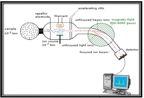
(2) Khatri Neetu et al. IRJP 2012, 3 (10) 2) Ionic source: Producing ions from the gaseous sample. 3) Mass analyzer: Separating ions of differing masses based on m/z ratio. 4) Detector: Detecting the number of ions of each mass produced. 5) Vacuum system: Create vacuum in the mass spectrometer 6) Recorder: Collating the data and generating the mass spectrum1.. Figure 1: Mass Spectrometer3. 1) Sample inlet system:- In sample inlet gaseous and volatile samples are introduced through a leak (pinhole restriction in a gold foil) of about 0.013 to 0.050mm in diameter into the ionization chamber from the inlet system. In this liquids are introduced in various ways like by touching a micropipette to a sintered glass disk under a layer of molten gallium, break-off device by hypodermic needle injection. Solids are directly incorporate in ion chamber with very low vapor pressure. 2) Ionic source:-From inlet system, the sample is introduced into ionization chamber where a beam of electrons is strike on the molecule of sample. These molecules become positively charged then they are accelerated by high voltage so that the energy of the electrons will be increased. Then the collisions occur between molecules and electrons which result in the production of fragments. Ionization methods in mass spectrometry are divided into two categories first, in gas phase ionization, the analyst is deal with volatile substance and sample is vaporized outside the ionization chamber. Second, in desorption technique, ions are formed from samples in the condensed phase inside the ionization chamber. Gas Phase 1) Electron impact 2) Chemical ionization 3) Field ionization Desorption 1) Field desorption. 2) Electron sprays ionization. 3) Matrix assisted laser desorption. 4) Plasma desorption. 5) Fast atom bombardment. 6) Secondary ion mass spectrometry. 7) Thermal ionization. 8) Ionization by ionic bombardment1. Acceleration: The positive ions which are formed in the ionization chamber are withdrawn by the electric field. These ions exist between the first accelerator plate and second. repeller plate. A strong electrostatics field accelerates the ions of masses to their velocities4. 3) Mass analyzers: In mass analyzers the ions are separated according to their mass/charge ratio. All mass spectrometers are based on principle of dynamics of charged particles in electric and magnetic fields in vacuum. In magnetic field the ion is go in to circular motion, and at the equilibrium5 BZV =mv2/r 5 Various mass analyzers are Magnetic analyzer · · double focusing analyzer · Time of flight analyzer Quadrupole analyzer · · Ion cyclotron analyzer · Ion trapped analyzer 4) Detectors: Ion beams after passing through mass analyzer, strikes on the detector. The ions, which have been separated according to their m/z ratio in the mass analyzer, can be electrically detected by detector. 5) Vacuum system: For the working of mass spectrometer, the ion source, the mass analyzer, and the mass detector must be kept under high vacuum condition of 10-6-10-7 torr (1.3×10⁻⁴ to 1.3×10⁻⁵)1. This high vacuum in spectrometer requires two pumping stages. The first stage is a mechanical pump which provides rough vacuum down to 0.1 Pa (10-3 torr) and the second stage uses turbo molecular pumps or diffusion pumps to provide high vacuum6. 6) Recorder: First of all, the sample is introduced into ionization chamber to produce positive ions. Then, the accelerating voltage (V) is adjusted to a high voltage to accelerate the mass particles to high velocity. Under these conditions particles of the lowest mass numbers will be deflected by the magnet. Particles with the lowest mass numbers reach the collector and are count. The accelerating voltage is then decreased so that mass numbers reaching the collector. When accelerating voltage becomes zero, the record of the distribution of the masses in the sample is complete and is present as a mass spectrogram. Two essential features of recorder are that · Recorders must have a very fast response, and able to scan several hundred peaks per second · They must be able to record peak intensities varying by a factor of more than 103.2 Detectors Ion beams after passing through mass analyzer, strikes on detector. The ions can be electrically detected by detectors which have been separated according to their mass / charge ratio in the system1. The choice of detector is based on the required detection sensitivity and the speed and it is also determined by other application-specific requirements, such as the thermal and chemical stability, required stability, and the amount of space available Desirable Detector Properties High amplification, Fast time response, Low noise, High collection efficiency, Low cost, Narrow distribution of responses, Same response for all masses, Large dynamic range, Long term stability, Long life, Mounted outside of the vacuum if possible, etc7. Type of detectors There are various types of detectors which are used in mass spectrometry. · Electron Multipliers · Faraday Cups · Photographic Plate Page 34.
(3) Khatri Neetu et al. IRJP 2012, 3 (10) · Scintillation Counter · Channel Electron Multipliers · Resistive Anode Encoder Image Detectors · High mass detection Detector Conversion dynodes · Helium Leak Detector · Advanced Detectors Cryogenic Detectors · Multi-Pixel Photon Counter · Other Detectors Electron Multiplier Detector For ion current less than 10-15 Amp An electron multiplier detector (EMT) is used. An electron multiplier detector is used to detect the ion signals emerging from the mass analyzer of a mass spectrometer1. Principle: The basic principle that allows an electron multiplier detector to operate is called secondary electron emission. When a charged ion (particle or electron) strikes on detector surface it causes secondary electrons which are released from atoms in the surface layer. The number of secondary electrons produced depends on the type of incident primary particle, its energy and characteristic of the incident surface8. Features of ETP Electron Multipliers • It has specialized surface material resulting in very high secondary electron emission. • Air stable. • Discrete dynode design results in extended operating life9. Detector design: There are two basic designs of electron multipliers that are commonly used in mass spectrometry are: the discrete-dynode electron multiplier and the continuousdynode electron multiplier8. Discrete-dynode electron multiplier: A typical discretedynode electron multiplier (as shown in figure 2) has between 15-18 dynodes with a metal oxide that has the property of high secondary electron emission. The dynodes are arranged in either box-and-grid fashion or venetian blind. Secondary electrons are constrained by a magnetic field to follow in circular path, causing them to strike on the dynodes1.. Figure 3: Continuous – Dynode Electron Multiplier7. Working Each dynode is connected to a resistor chain and the first dynode is at ground potential, so that both positive and negative ions may be detected. The last dynode can be between +1500 to +3500 V depending on the type and age of electron multiplier. When an ion (electron, neutral, etc.) strikes the first dynode it may produce a few (1, 2 or 3) secondary electrons which are accelerated to the second dynode that is held at higher positive potential to generate more secondary electrons and a cascade of secondary electrons ensues. Figure 4 shows a basic EMT. For optimum performance, the electron multiplier should operate at sufficiently high voltage So that every ion arrival produces a pulse and then this pulse is amplified and as long as it is above a set threshold, it will be passed to the counting circuit. The time taken for the multiplier, discriminator, and amplifier to produce a pulse is known as the dead time (t). With fast pulse-processing circuitry, this is in the order of 15 to 20 ns and the maximum count rate of electron multipliers is about 5x10⁶ c/s if the dead time correction is to be kept low. The percentage correction is about 1.3% when a dead time of 25 ns and count rate of 5x10⁵ c/s. The true count rate (n) may be calculated from the observed count rate (no) by the equation:. n= true count rate n0= observed count rate t= dead time Pulse counting detectors based on the principle Poisson statistics which require that each ion arrives independently of all other ions. If, in a fixed interval of time, n counts are detected, the standard deviation of the measurement is given by:. Figure 2: Principle of the Discrete-dynode electron multiplier7. And the relative standard deviation is given by11:. Continuous - dynode electron multiplier The tube is made of glass which is impregnated with lead (as shown in figure 3) to produce a desired resistance between the anode and cathode. Thus there is a continuous voltage drop along the tube to accelerate the electrons; the curvature ensures that the accelerated electrons will undergo secondary electron emission10.. Page 35.
(4) Khatri Neetu et al. IRJP 2012, 3 (10). Figure 4: Electron Multiplier Detector assembly12. Recent developments In recent developments, molecules of higher mass can also be detected and enhanced lifetime under the less than ideal environments typically encountered in mass spectrometers. Magnum ETP Magnum ETP (see figure 5) offers exceptional performance for optimum mass resolution, detection sensitivity and dynamic range12. Finally, the use of the SpiraltronÔ technology in (as in the Magnum Ô Electron Multiplier) mass spectrometer which is coupled with improved materials and processing has the potential to significantly enhance the lifetime of current detectors over those detectors which are manufactured in the early days of the industry13.. Advantage · The multi-dynode approach of all electron multiplier detectors which results in longer lifetimes and better sensitivity compared with channel electron multipliers (CEM) or continuous-dynode multipliers. · Optimized ion and electronic optics for maximum performance. · Increased surface area for enhanced sensitivity and extended operational life. · Low noise7 Disadvantage The main disadvantage of electron multiplier detector is that the bias voltages for each element have to generate in a chain of resistors, and this chain draws a fair amount of current from the negative voltage supply. FARADAY CUP COLLECTOR The count rates of Faraday cup detector is about 5x10⁴ c/s upwards. Design: - A faraday cup is a metal conductive cup designed to catch charged particles in vacuum with suppressor electrode and then producing current which can be measured and used to determine the number of ions striking the cup. Working: - The Faraday cup detector consists of a hollow conducting electrode connected to ground through a high resistance. The ions strike on the collector cause electrons flow from ground via the resistor. The resulting drop of potential is amplified across the resistor. A plate is held at about -80 V in front of the collector as in figure 7 that prevents ejected secondary electrons from escaping and causing an anomalous reading. A single charge on a single ion is 1.6x10⁻¹⁹ C. Therefore a count rate of detector is 1x10⁶ c/s that would produce a current of 1.6x10⁻¹³ Amps. With a resistor of 10 MW connected to ground and the amplifier must be able to detect a potential drop of 1.6x10⁻⁶ (0.0016 mV). The detection limit of the Faraday cup collector is limited by the quality of the amplifier and the thermal noise in the resistor. Often these components will be enclosed within thermally controlled evacuated chamber. Faraday cup collectors are not as sensitive as electron multiplier detectors, but they have high accuracy because of the direct relation between the numbers of ions and measured current11.. Figure 5: Magnum Electron Multiplier12. The exceptional performance of the detector results in reduced system linearity due to the limitation of the electron multiplier supplied as original equipment. The ETP detectors overcome this limitation that showed in identical performance Comparison undertaken at independent laboratories8. (Figure 6). Figure 7: Faraday cup collector11. Figure 6: Detector response comparisons for tetrachlorophenol8. Advantage · More sensitive and produce current up to 10-15 Amp. and larger · Signals from this collectors are stable and reproducible · Simple Construction11. Disadvantages · They have low sensitivity due to the current induced in the circuit by ion beam are very small. · It does not identify between the type of ions or its energy14. Page 36.
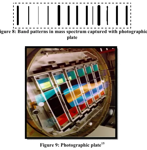
(5) Khatri Neetu et al. IRJP 2012, 3 (10) PHOTO GRAFIC PLATE DETECTOR Photographic plate detector can give great resolution and high speed than other electronic devices. It can detect ions of all masses simultaneously and provides reverse- geometry. It is a time integrating device. These detectors generally used with radio frequency spark instruments. This is the simplest and oldest form of detector and they can be used in planefocusing instruments and detects all ions and the intensity of the mark on the film is proportional to the abundance of the ion. The main advantage of the photographic plate detector is when it is used in a double-focusing mass spectroscope in which the whole or a major part of the mass spectrum is focused in a plane. In this case, one can make use of the integrating action of the photographic plate. When the ions strike the plate they leave dark tracks on plate (shows in figure 8) when the plate is developed. The intensity of these dark tracks is related to the number of ions of mass to charge ratio striking the plate at each point15.. Figure 8: Band patterns in mass spectrum captured with photographic plate. first dynode. The incident electron causes multiple numbers of secondary electrons to be emitted, which accelerate towards and strike on the second dynode. More secondary electrons are emitted and the electron multiplication chain continues through the increasing the dynodes potentials, with increasing numbers of secondary electrons generated each time. By this time the electrons reach the anode, enough have been released to generate a measurable voltage pulse across resistors. This voltage pulse is amplified and recorded by the processing electronic. Advantages · This detector has an extended life and more stable than the conventional electron multiplier. · It opens the possibility of using photon counting techniques. · High sensitivity Uses Scintillation counters are used to measure radiation in various applications. · Hand held radiation survey meters · Environmental and personnel monitoring for Radioactive contamination · In medical imaging · Homeland and national security · Safety of nuclear plant · Radon levels in water16. Figure 9: Photographic plate15. SCINTILLATION DETECTOR Scintillation counter detectors are very similar to the detector used in radiochemical application. Design: - A modern scintillation detector consists of three parts: a scintillator, a photomultiplier and signal processing electronics (figure 10). These detectors consist of conventional end window photomultiplier on this a thin disk of crystalline phosphor is mounted that maintained at a potential of +10KV. Photomultiplier absorb the light emitted by the scintillator and reemit this light in the form of electrons via the photoelectric effect. Principle: - In the scintillation detector the energy of the incident particle is converted into light pulses. This scintillation light travels through the scintillator volume and hits the photocathode of the photo multiplier, where it releases photo electrons. Working:- When a charged particle strikes on the scintillator, the atoms of the phosphor are excited and emit photons, which are directed at the photocathode of the photomultiplier tube. The tube is connected to the negative of a high voltage source. Each incident photon releases an electron. A number of accelerating electrodes are arranged in the tube at increasing positive potentials called dynodes and the electrons are accelerated by this electric field towards the. Figure 10: Scintillation Detector7. CHANNEL ELECTRONE MULTIPLIER Channel Electron Multipliers (CEMs) are efficient and durable detectors that directly detect and amplify charged particles and energetic photons such as positive and negative ions, electrons and assorted molecular and subatomic particles13. Design In CEMS each channel is made from semiconducting lead glass with a high voltage applied between the ends like before. A large number of glass optical fibers are combined together, which are drawn out to decrease their cross section (in figure 11). The core of the fiber is dissolved away leaving hollow tubes and the cut into slices. The faces of the plate are coated with Specific metal which provide a conducting path for the bias voltage. Each slice is about 2 mm thick and 25 or 50 mm in diameter. Each fiber ends up about 12 μm in diameter with a channel about 10 μm across and these channels are tilted with respect to the plate so that incident charged particles do not pass straight path. The plate emits 103 to 104 electrons and often two of them are stacked together. These detectors can be used in image intensifies (e.g. in night vision goggles), of in situations where large dynamic range in ion flux is needed. Since each channel Page 37.
(6) Khatri Neetu et al. IRJP 2012, 3 (10) works as a separate multiplier, and there are a large number of channels, the device is linear up to fairly large incident flux17. Working An ion strikes on the input surface of the device that produces 2-3 secondary electrons. These secondary electrons are accelerated down the channel by a positive bias voltage and strike the channel walls (shows in figure 12), producing additional secondary electrons (and so on) until, at the output end a pulse of 107 to 108 electrons emerges. For detection of positive ions, the input is generally at a negative potential of about 1200 to 3000 volts and the output is at ground potential. For detection of negative ions, the input is at ground or some positive potential and the output is at a high positive voltage. This requires some form of decoupling in order to handle the high voltage signal18.. Figure 13: Miniature Channeltron® Electron Multiplier. Spiraltron™ High Pressure Electron Multipliers These are specifically designed for high pressure applications, such as portable mass spectrometers. It consists of a six channel structure (as in figure 14) which has been spiraled for optimally reduce ion feedback. The number of spirals per inch can be changed that resulting in a longer or shorter travel path. Spiraltron™ Electron Multipliers can operate at pressures 10-3 Torr range.. Figure 14: Spiraltron™ High Pressure Electron Multiplier Figure 11: Cross section of channel plate17. Mega Spiraltron™ High Pressure Electron Multipliers The Mega Spiraltron™ uses the same technology as a Spiraltron™, but in a small housing which results high gain and low noise. These detectors can be manufactured with customized options to enhance detection capability. The Mega Spiraltron™ operates at pressures as high as 10-2 Torr20 (in figure 15).. Figure 12: Electron Multiplications in the Channel Plate18. Advantages · High gain · High temporal and spatial resolution. Applications They can be used in various applications including · In imaging spectroscopy · In electron spectroscopy and microscopy · In astronomy · Molecular and atomic collision studies19 Recent development of Channel Electron Multiplier Miniature Channeltron® Electron Multipliers: - These detectors are the ideal choice for low-cost instruments or pulse counting applications due to a combination of gain (greater than 10 million) and low noise (as shown in figure 13). Applications In leak detectors, portable mass spectrometers, and enviornmental sensors.. Figure 15: Mega Spiraltron™ High Pressure Electron Multipliers20. RAE (RESISTIVE ANODE ENCODER) IMAGE DETECTORS The resistive anode encoder (RAE) is a position-sensitive detector. It is used to digitally record images of ions. The background count rate is high, but it is constant over a period of time, and the maximum count rates must be less than 4x10⁴ c/s. Because this detector uses a micro-channel plate for the ion to electron conversion so the detector discriminates between species. An ion strikes on a channel in the first of two micro-channel plates. The ion to electron conversion results formation of pulse of electrons that emerge from the back of the first plate to initiate a second electron cascade in the channels of a second plate. The resulting electron pulse strikes a resistive anode plate (shows in figure 16) comprising a thick resistive film which is deposited on a ceramic plate. The geometry of Page 38.
(7) Khatri Neetu et al. IRJP 2012, 3 (10) this detector is designed to avoid image distortion. The charged pulse is partitioned off to four electrodes at the corners of the resistive plate. The pulses are amplified and then passed to the position computer where the X and Y position is calculated by the equations: X = IB+IC / IA+IB+IC+ID Y = IA+IB / IA+IB+IC+ID The calculation of the electron impact position can take a long time (2-3 μs), resulting in an overall dead time of 4.3 μs11. Figure 17: High Energy Dynode Detector7 Table 1: Comparison of Detectors7 Advantages Disadvantages Good for checking ion Low amplification transmission and (≈10) detector sensitivity Scintillation Extremely robust, Long Cannot be exposed to counter life time (>5 years) light Good sensitivity (≈106) Electron Fast response Sensitivity Short lifetime (1-2 multiplier years) (≈106) High energy Increase high mass May shorten lifetime dynodes with sensitivity of electron multiplier electron multiplier Detector Faraday cup. Figure 16: Resistive Anode Encoder11. HIGH MASS DETECTION DETECTOR There has been a significant increase in interest in detection of ions that have high mass. The definition of high mass depends on one’s perspective that those engaged in residual gas analysis, high mass of ions might be anything in excess of 200 Daltons, while a LC/MS and biomedical applications require detection of ions from tens and even hundreds of thousands of Daltons and GC/MS application may require detection of ions from 700-2000 Daltons. The detection efficiency decreases nearly exponentially with increasing mass of ions and becomes negligible to solve this problem several approaches have been developed, including the use of higher impact energies and high energy conversion dynodes CONVERSION DYNODES A conversion dynode is used to increase the secondary electron emission characteristics for high mass ions and reduce the mass discrimination of the detector. Design: - A conversion dynode is simply a metal separate surface which can be held at a high voltage at 3 to 20kV or more. The potential of dynode serves to accelerate the ions to a point where good conversion efficiency for either electrons or secondary ions occurs. The CEM is then used to detect the secondary electron emission from the dynode surface. Working:Conversion dynodes are used in the detection of positive ions and the conversion products are thought to be lower mass ions and electrons. The high negative potential on the dynode surface serves to direct electrons toward the channel electron multiplier input which is held at a low negative potential. A high positive potential on the Conversion dynode will not produce many secondary electrons being collected by the CEM (as given in figure 17) since the dynode will tend to recapture electrons21.. HELIUM LEAK DETECTOR A helium leak detector is an instrument commonly used to locate and detect small leaks. Principle A helium leak detector (in figure 18) allows the localization of leaks and the quantitative determination of the leak rate such as the gas flow through the leak. Such a leak detector is a helium flow meter and performs this task by firstly evacuating the part to be tested, so that gas may enter through a leak from the outside due to the pressure difference present. If only helium is in front of the leak (e.g., by using a spray gun) this helium flows through the leak and is pumped out by the leak detector. The partial pressure of helium present in the leak detector is measured by a sector mass spectrometer and is displayed as a leak rate. This is usually given in terms of volume flow of the helium (pV-flow)22. Advantages: - It is very Fast, More sensitive, more reliable, improved product quality, Easy operation, and Cost saving23. Uses:- Helium mass spectrometer leak detectors are used in production industries such as refrigeration and air conditioning, food packages, automotive parts, carbonated beverage containers and aerosol packaging, as well as used in the manufacture of steam products, gas bottles, tire valves, fire extinguishers and various other products including all vacuum systems22.. Page 39.
(8) Khatri Neetu et al. IRJP 2012, 3 (10). Figure 18: Helium Leak Detector22. ADVANCED DETECTORS At present, routine DNA analysis is done by mass spectrometry is seriously constrained to small DNA fragments and the application of mass spectrometry on those procedures that identify short DNA sequences. This approach helps the molecular biologists which are associated with LBL’s Human Genome Center to identify redundant DNA sequences and vector contamination in clones, thereby improving sequencing efficiency. With the use of conventional electron multipliers one of the limitation of mass spectrometry in DNA analysis is its poor efficiency .To solve this problem, alternative detection schemes which works on heat pulse detection is developed. When ions strike a detector, the kinetic energy of striking ions is converted into heat and then measures indirectly such heat pulses. Developing a type of cryogenic detector (as given in figure 19) called a superconducting tunnel junction device which produced photons when ions strike the detector. This detector does not base on the principle of the production of secondary electrons. This type of detector to be at least two order of magnitude which is more sensitive, on an area-normalized basis, than micro channel plate ion detectors. These detectors could extend the upper mass limit large ions. In this electro spray ion sources generate ions of mega-Dalton DNA with minimum fragmentation, but the mass spectrometric analysis of these large ions usually leads only to a mass/charge distribution. If charge of ion was known, actual mass data could be determined. To solve this problem, develop a detector that will measure the velocity and charge of individual ions. Mass analyze DNA molecules in the 1 to 10 Mega Dalton range using charge-detection mass spectrometry. In this technique, individual electro spray ions are strike through a metal tube which detects their image charge. When ions of known energy are sampled than simultaneous measurement of their velocity provides a way to measure their mass. By this method several thousand of ions can be analyzed in a few minutes, thus generating statistically significant mass values regarding the ions in a sample population25. Applications of cryogenic detectors: · For the study of low energy beta decays to investigate the existence of massive neutrinos. · For the identification of biological macro-molecules e.g. DNA-sequences, proteins, and polymers is essential for research in modern bio-chemistry and for the fabrication of new materials, and medication25.. Figure 19: Cryogenic Detector25. MULTI-PIXEL PHOTON COUNTER (MPPC) Multi Pixel Photon Counter is a novel type semiconducting photon sensor or counter. It has great photon detection ability, good cost performance and very compact size. It will displace the expensive and big Phototubes in near future26.. Figure 20: Multi-Pixel Photon Counter26. Design: It consists of an array of Avalanche Photo-Diode pixels on area of 1x1mm2. Each pixel consists of p and n-type semiconductor above p- layer (as figure 20) called depletion region that is surrounded by guard ring placed for isolation from other pixels. Apply about 70 V of reverse bias voltage to the p-n junction plane that creates strong electric field in the depletion region. If a photon strike on a pixel, the photon blow up an electron and the electron induces inundation in the depletion region. Thus the pixel "fires" signal.. Figure 21: Multi-Pixel Photon Counter27. Since each pixel exist in two states, "fired" or "not fired", the MPPC have multi-pixel structure. By counting number of "fired" pixels, one can know number of photons injected into the detector26. Page 40.
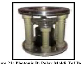
(9) Khatri Neetu et al. IRJP 2012, 3 (10) Working: - Each Avalanche Photo-Diode micropixel independently works in Geiger mode with an applied voltage a few volts above the breakdown voltage. When a photoelectron is produced and induces a Geiger avalanche. This avalanche is passively quenched by a resistor integral to each pixel. (In figure 21) The output charge Q from a single pixel is independent of produced photoelectrons within the pixel, and can be written as Q = C (V − Vbd), Where V is the applied voltage and C is the capacity of the pixel. Combine the output from all the pixels, the total charge from counter that is quantized to multiples of Q and proportional to the number of pixels that underwent Geiger discharge. The number of fired pixels is proportional to the number of injected photons if the number of photons is small and compared to the total number of pixels. This detector has an excellent photon counting and detection capability27. OTHER DETECTOR KEVO® TQD TANDEM QUADRUPOLE MS DETECTOR This detector collect high specific quantitative data for target compounds, while provide the ability to visualize all other components. Features: This detector has wide range of ionization capabilities today, future-proofing for the innovations. These are designed to reduction of complexity; ensure correct result and increase ease of use is delivered every time. (Figure 22). Figure 22: Kevo® Tqd Tandem Quadrupole Ms Detector. PHOTONIS BI POLAR MALDI TOF DETECTOR Theses detectors improve the detection efficiency of very high mass of ions. Features: - It has large 250 mm2 collection area which allows higher sensitivity without the need for higher post acceleration voltage. It consists of a high-sensitivity microchannel plate, a photomultiplier and a high-speed scintillator (shows in figure 23) which can detect both positive and negative ions with 30 kV isolation.. Figure 23: Photonis Bi Polar Maldi Tof Detector. FLEXAR SQ 300 MS DETECTOR Features: - This detector has advanced design in ion source and mass spectrometry technology that Provides soft ionization in rugged design. This detector attains a new level. of sample insight through speed, confirmatory analysis and high sensitivity28. (Figure 24). Figure 24: Flexar Sq 300 Ms Detector28. CONCLUSION Currently, the old detection techniques used in Mass spectrometry are replaced by recent detection techniques for their higher sensitivity, more quantitatively accurate information, or more immediate data availability are required. Mass spectrometry detectors are capable of determining the spatial distribution of particles, whether photons, neutrons, atoms, or others, have long existed. More recently, detectors has been applied to mass spectrometry for the simultaneous detection of multiple ions of differing mass-to-charge (m/z) values. When simultaneous detection is utilized in mass spectrometry, benefits such as improved detection limits and precision can be obtained. REFERENCES 1. Willard Hobart H., Et al. ‘Instrumental Method of Analysis’ 7th Edition, 1986, Published by CBS Publishers and Distributors, New Delhi, 465469, 476, 486-488 2. Kemp William, ‘Organic Spectroscopy’ 3rd Edition, 1991, Published by Palgrave, New York, 286, 292 3. Mass Spectrometry, 2009, [Cited 2012 Feb 20], Available from <http://www2. chemistry.msu.edu/faculty/reusch/VirtTxtJml/Spectrpy/MassSpec/massp ec1.htm> 4. Chatwal G.R. and Anand S.K. (2005). Instrumental Methods of Chemical Analysis, Himalaya publishing House, New Delhi, 2.2742.277 5. Kalsi P.S., ‘Spectroscopy of Organic Compounds’ 4th Edition, 2004, Published by New Age International Pvt. Limited, New Delhi, 425 6. Bramer Scott E. Van, ‘An Introduction to Mass Spectrometry’ Copy roght 1997, [Cited 2012 Feb 12], Available from <http://science.widener.edu/svb/massspec/ massspec.pdf> 7. Jimenez J.L. ‘Mass Sectrometry Detectors’ 2007, [Cited 2012 March Available from 22], <http://www.colorado.edu/chemistry/chem5181/Lectures07/2007 _MS4_Detectors_SNR.pd> 8. ETP electrone multiplier, Electron Multipliers for Mass Spectrometry, [Cited 2012 aprail 02], Available from <www.bgbanalytic.de/pdf/sge_multipier.pdf> 9. Benes S., NEW! Electron Multipliers for Mass Spectrometry, 2008, [Cited 2012 aprail 22], Available from < http://www.restek.com/pdfs/adv_2008_01_16.pdf > 10. Mass Specs Term Projects, Continuous dynode particle multiplier, 2010, [Cited 2012 Feb11], Available from <http://massspec.lsu.edu/msterms/index.php/ Continuous_dynode_particle_multiplier> 11. Secondary Ion Mass Spectrometry, [Cited 2012 March 30], Available from <http://www.geos.ed.ac.uk/facilities/ionprobe/SIMS4.pdf> 12. Channeltron® Electron Multipliers, Photonis, 2012, [Cited 2012 May 30], Available from <http://www.photonis.com/en/ism/59-magnumelectron-multipliers.html> 13. Channeltron Electron Multiplier Hand book for Mass Spectrometry Applications, [Cited 2012 March 16], Available from < www.burle.com/electmultdet.htm> 14. Vogal, Text Book of Quantitative Chemical Analysis, 2008, 6th Edition, Published by Pearson Education, South Asia, 765, 766 15. Encyclopædia Britannica, Mass Spectrometry, 2012, , [Cited 2012 Feb 28], Available from. Page 41.
(10) Khatri Neetu et al. IRJP 2012, 3 (10) 16. 17. 18.. 19. 20. 21.. <http://www.britannica.com/EBchecked/topic/368325/massspectrometry/80553/Combined-electric-and-magnetic-field-analysis> Dyer S. A., Survey of Instrumentation and Measurement, 2011, published by John Wiley & Sons, England, 920 Mass Spectrometry, [Cited 2012 March 28], Available from <http://www.ph. utexas.edu/~gositz/phy386_MassSpec.pdf> McGraw-Hill Concise Encyclopedia of Physics, Channel Electron Multiplier, copyright 2002, published by The McGraw-Hill Companies, Inc., [Cited 2012 March 28], Available from <http://encyclopedia2.thefreedictionary.com/ channel+electron+multiplier> Del Mar Ventures, Microchannel Plates and Microchannel Plate Detectors, [Cited 2012 May 08], Available from <http://www.sciner.com/MCP/MCP.htm> Channeltron® Electron Multipliers, Photonis, 2012, [Cited 2012 May 30], Available from <http://www.photonis.com/en/ism/25-channelelectron-multipliers .html> Mass Specs Term Projects, Conversion dynode, 2006, [Cited 2012 March 28], Available from <http://massspec.lsu.edu/msterms/index.php/Conversion_ dynode>. 22. INFICON, Leak Detector Catalog, 2007, 1-36, [Cited 2012 March 28], Available from <http://www.inficon.com/download/en/copy%20leakdet%20 catalog.pdf> 23. ULVAC Technologies, inc. Helium Leak Detection Principles, copyright 2011, [Cited 2012 Feb 18], Available from <http://www.ulvac.com/industrial_auto/ principles.asp> 24. Benner W.H., Jaklevic J.M., Human Genome Program Report Part II 1996 Sequencing Abstracts, University of California; Berkeley, 19 25. Applied Cryodetectors, [Cited 2012 April 23], Available from <http://www. physics.ox.ac.uk/cryodetectors/research.asp> 26. MPPC, Multi Pixel Photon Counter (MPPC) @ GLDCAL, 2006, [Cited 2012 April 13], Available from <http://ppwww.phys.sci.kobeu.ac.jp/~kawagoe/gldcal/ index.php?MPPC> 27. Yokoyama M., et al. (2006) Development of Multi-Pixel Photon Counters. Japan, 1 28. Lab Manager Magazine®, Mass Spectrometry Detectors, 2012, [Cited Available from 2012 May 13], http://www.labmanager.com/?articles.view/articleNo/29985 /. Source of support: Nil, Conflict of interest: None Declared. IRJP is an official publication of Moksha Publishing House. Website: www.mokshaph.com. All rights reserved.. Page 42.
(11)
Figure


+5


Related documents
In the resistance state, the information of the experience of successful resisting competitor persuasion and the connection knowledge with target product or brand
In export activities, firms behave differently according to the characteristics such as productivity level, size or product lines they own, the market entry costs they face,
In this paper, single line contingency analysis for the Nigeria 330kv post-reform grid to determine violations in the network due to the individual contingencies were considered
A range of capacities is required to facilitate curriculum implementation that is understanding: core conceptscurriculum implementation cycle;approaches to
Background: Cytoreductive surgery (CRS) with heated intraperitoneal chemotherapy (HIPEC) has gained acceptance in the treatment of peritoneal carcinomatosis (PC) with reported
Following the theoretical framework, the four empirical chapters are devoted to charting the contours and manifestations of militarised statebuilding in South
In the case of this project, the remarkable proliferation of Buddhist monuments and inscriptions in the reign of Jayavarman VII, displays a full commitment to Buddhism, but in
