Control of a Dc Motor using Sensorless
Observer Based Sliding Mode Control Method
Tayfun Abut1
1
Department of Mechanical Engineering, Mus Alparslan University, Mus, Turkey
Abstract
Sensorless control methods are one of the control methods that continue to develop in recent years.In these control types, the target rotor is to obtain the speed and position information from the measured quantities such as voltage and current. There are several methods for sensorless control. These methods are usually affected by the dc motor's parameter changes, uncertainties and disturbing factors, which leads to a reduction in the quality of the control. In this study, an observer-based sliding mode control method is proposed for position and speed-free control of a DC motor. Luenberger and Kalman filter observer methods were used as observers for control of DC motor. The saturation function is used for the cracking problem of the sliding mode control method. Both the process noise and the measurement noise were applied to control the DC motor system in conditions close to the actual ambient conditions. A second-order low-pass filter design has been designed to improve the performance of the controllers in the noise environment. As a result of these studies, the controller was designed and graphical results were obtained in order to be used in a real physical environment. The control methods applied according to the results of the simulation environment were compared and the results were examined.
Keywords — Sliding Mode Control Method, Luenberger observer, Kalman Filter, Sensorless, DC motor
I. INTRODUCTION
Direct current (DC) motors are used frequently because of their features such as cost, ease of control, long life and quiet operation. DC motors for robotics, defense industry and automotive applications etc. are used in many fields [1-10]. In recent years, sensorless control methods have been used in the control of dc motors [11-15]. During the control of most systems, there is only parameter information and partial status over the measured outputs, which usually limits the performance of the system.In order to recover unknown situations and parameters, powerful observers with high estimation accuracy are required. Many effective technologies andmethods have been developed to solve case and parameter estimation problems.
Control studies using observer-based control methods (Kalman filter, adaptive, sliding-mode
observations, Luenberger, etc.) have been done in the literature [16-22]. The sliding mode control was the result of the studies carried out in the 1950s. In 1976, Itkis [23] and Utkin [124-25] in 1977 with the work of this control method is the basis. The sliding mode control is a special case of the variable structure control. First, a surface is selected and the surface is referred to as the sliding surface. This surface is selected in the state space. First, state variables are forced to go over the slip-surface. After the state variables reach the slip surface, the control signals that are directed to the origin on this surface are determined. In this method, first the state variables are forced to go onto the sliding surface and are then shifted on the surface and then shifted towards the origin. It is therefore also referred to as the sliding surface, also called the switching surface. Due to the nature of this method has a non-continuous control structure. This discontinuous control sign leads to cracking. This damages the physical system elements. One way to prevent this is to replace the discontinuous signum function in the sliding-mode control signal with the saturation function, a continuous approach of this function [26-27]. Many methods are usually affected by dc motor parameter changes, uncertainties and disturbing factors, which leads to a decrease in the quality of the control. Due to model uncertainties and resistance to external factors and nonlinear structure, sliding mode control method is preferred for controlling DC motor. In this study, an observer-based sliding-mode control method is proposed for position and speed-free control of a DC motor. For the control of the DC motor, the observer type Luenberger and Kalman filter observer methods were used. The saturation function is used for the cracking problem of the sliding mode control method. Both the process noise and the measurement noise were applied to control the DC motor system in conditions close to the actual ambient conditions. A second-order low-pass filter design has been designed to improve the performance of the controllers in the noise environment. The control methods applied according to the results of the simulation environment were compared and their results were examined.
II. STATE STACE MODEL OF DC MOTOR
rotation and offset movement. DC motor model is shown in Figure 1.
a K
a
e ia
a
L
m
m
L T Magnetic flux
m T
Fig. 1 Dc motor model
Moment received from the electric motor;
(1)
(2)
T
m=Ki.Ia (3)
(4)
(5)
If we take our variables as ia, m and m, the equations of state from the first order can be written as follows.
(6)
(7)
yC xD u
(8)
The parameters of the dc motor are shown in the Table 1.
TABLE I PARAMETERS OF DC MOTOR
Sembol Description Units Value
m Body Mass kg 10
J Body Inertia kgm2 0.171 Km Motor Constant Nm/A 3520 Ra Motor Resistance Ohm 55
lo Leg Length m 0.323
Lm Motor electric inductance
H 0.3
Bm Damping ratio of the
system friction constant Nm. 0.097
III.THE CONTROLLER DESIGN
Control performances were performed by using different observers in control of DC motor. In the control systems used, the purpose is that the output value of the system follows the targeted value. This
error is minimized by the controller applied to the system.
A. Sliding Mode Control
The sliding-mode control (SMC) method was used to control this system[28-33]. The control variable of the system is the position angle of the motor. The position angle of the system has been checked in the presence of disturbing effects. Figure 2 shows the block diagram of the sliding-mode control (SMC) method.
Sliding Mode Controller
/
d dtd/dt Dc motor Model
d
q e
.
e
q qObserver
Fig. 2 Block diagram of the control structure system
( ) d( ) ( )
e t q t q t
(9)
( ) ( ) ( )
.
d
e t t t
(10)
In the above equation, qd denotes the desired joint trajectory and q shows the true trajectory. The first and second-degree derivatives were used for equation 9.
.
S e e (11)
. ..
.
S ee (12)
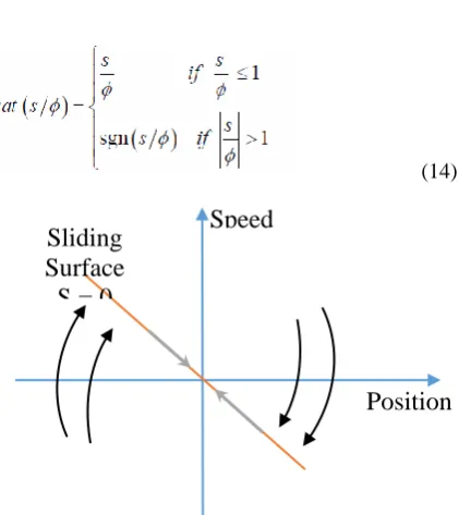
S shows the sliding surface. Equations 11 and 12 were obtained. λ is a positive defined symmetric matrix. k is the constant parameter with the equation 13. Signum is a signal function and s functions as a switch. Figure 3 shows the concept of the sliding surface.
* ( )
u k s ig n S (13)
(14)
Fig. 3 The concept of the sliding surface.
Speed
Position
Sliding
Surface
S = 0
) ( . ) ( . . )
(t K i t K i t
Tm m a i a
b a a a a a a a
e L i L R e L dt di
. 1 . . 1
Lyapunov criteria were used for the stability of the system. Saturation function is used to solve the chattering problem. shows the thickness of the boundary layer.
1
2
T
V S S (15)
S ≠0 for V>0. The derivative of the equation 15 was
obtained to obtain the number 11.
.
V is <0.
1
2
.
T.
TV S S S S (16)
B. Sensorless Control
The traditional method for measuring the speed of DC motors uses a tacho-generator that converts the speed to the corresponding voltage. The output voltage can be used as feedback to control the speed of the DC motors. In this study, motor speed measurement system is applied without mechanical components. The transfer function or status area analysis is one of the popular methods of controlling the speed of DC motors without speed sensor [34]. The method converts the DC motor's continuous-time system parameters to state space form. The system inputs are armature voltage and armature current and the system output is the speed of the DC motor. The position can be estimated by integrating the speed. In this study, Luenberger and Kalman filters were used for the estimation of speed.
C. Luenberger Observer
A system is generally used as an information in the system's state feedback control by making it measurable by measuring with sensors. However, it is sometimes necessary to estimate the non-measurable state variables such as the cost of the sensors and in some cases, there is no sensor to provide that measurement. It is called stateobservation that these variables can be measured by using measurable state variables and measurable outputs of the system. and the tools used for this process are also called status monitors or briefly observers. The most well-known and most frequently used observer is the Luenberger observer [35-38]. The problem in this study is the estimation of the angular velocity of the dc motor. Using the dc motor state space model, the engine was estimated using the angular velocity observer. State space model equations of the observer can be given as follows:
^ ^ ^
( )
x A x B u L y C x (17)
^
y C xv (18)
The ^
x values given in the above equations show the predicted states, the inputs u, the outputs y, the observer gain matrix L, the measurement noise v. The
block diagram of the system and the observer is given in Figure 4.
Dc Motor Model
Luenberger Observer
r
^
x u
,system states ,system outputs
,observer states
,observer outputs
^
y
x
yFig. 4 Block diagram of the Leuenberger observer and system
While the observer gain matrix L is found, the monitor's poles are selected to the left of the system poles at least 10 times faster than the system poles so that the observer's estimation error converges to the zero quickly and the effect of the monitor on the system response is minimized. To be able to design a system for a system, it must be observable. The system has been found to be fully observable for all velocity and motor friction coefficients in the dc motor model. In this study, the Luenberger observer was used in the first studies and then the Kalman filter which is an advanced observer was used for speed estimation.
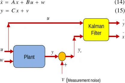
D. Kalman Filter Design
Kalman filter is a filter estimating the status of the systems using the input and output information [39-42]. It has become one of the popular control methods for the DC motors without the transfer function or the state-space speed sensor. The inputs of the system are the armature voltage and armature current, system output is the speed of the dc motor in this system. Kalman filter is a kind of filter that can conduct optimally filter the operation and computation noise as long as the covariance of the noise is known. Estimation with this filter results in minimizing the covariance matrix of the fault for the systems exposed to Gauss computation or operation noise. State space model equations of Kalman estimator can be given as follows:
x A x B u w (14)
y C x v (15)
Kalman Filter
Plant
u yv
v
w
~ x
u
y
~
y
(Measurement noise)
Fig. 5 Block diagram of the Kalman estimator
x A x B u w (16)
^ ^ ^
( )
x A x B u L y C x (17)
^
x it is the estimated x value.
1
T T
A P P A P C R C P Q (18)
Q must be positively defined and R must be positive semi-defined and the system must be observable. Operation noise is expressed as w~N(0, Q) and measurement noise is expressed as v~N(0, Q). Here, Q is the input covariance matrix and R is the output covariance matrix. P algebraic invariant minimizing the cost function is calculated with the Riccati equation. Filter gain, L, is calculated as shown with the Riccati equation.
1
T
L P C R (19)
IV. NUMERICAL SIMULATION
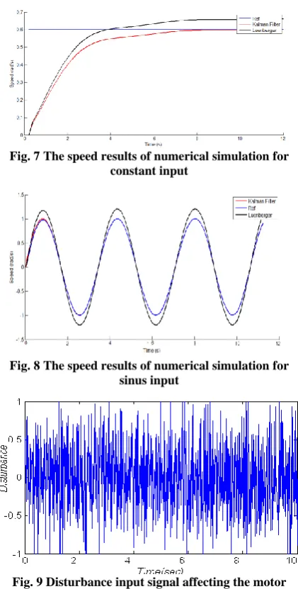
In this section, the sliding-mode control method based on the Luenberger and Kalman filter monitors given above is used. The design, calculations, and simulations of the methods were made. The observer-based control of the Dc motor was simulated using the parameters shown in Table 1. In simulation studies, sensorless speed control was performed by using observer-based control methods. The most important point in this study is that the controllers are stable and the system performs the desired task with minimum error rate. The following figures show the motor speed graphs according to the reference speed change.The Luenberger observer-based sliding-mode control method has generally followed the reference with more amplitude. According to observer method, settling time, overshoot etc. parameters differ from each other. Figure 6,7 and 8 shows every control techniques in one graphic, Kalman filter based sliding mode control has the best settling time over Luenberger observer sliding mode control. Kalman filter-based sliding mode control method gave the best results.
Fig. 6 The speed results of numerical simulation for square input
Fig. 7 The speed results of numerical simulation for constant input
Fig. 8 The speed results of numerical simulation for sinus input
Fig. 9 Disturbance input signal affecting the motor
V. CONCLUSIONS
In this study, the design and simulation of Luenberger and Kalman filter-based sliding-mode control are performed for dc motor speed control. It has been seen that the chattering problem of the sliding mode control method is solved by the saturation function. In order to control the DC motor under conditions close to the actual ambient conditions, both noise and measurement noise was applied. A second order low pass filter design has been applied to increase the performance of the controllers in the noise environment. The Kalman filter-based observer gave the best results. As a result of the comparison of observer-based control methods, it was observed that the controllers gave satisfactory results. In future studies, the proposed observers are intended to be developed and implemented on a real system.
REFERENCES
torque ripple minimization. Transactions of China Electrotechnical Society, 29(1), 139-146,(2014).
[2] Schmidt, R. A., Lee, T., Winstein, C., Wulf, G., & Zelaznik, H. Motor Control and Learning, 6E. Human Kinetics, (2018).
[3] Blakemore, R. L., Sinanaj, I., Galli, S., Aybek, S., & Vuilleumier, P. Aversive stimuli exacerbate defensive motor behavior in motor conversion disorder. Neuropsychologia, 93, 229-241, (2016).
[4] Zhang, Z., Zhang, X., Chen, W., Rasim, Y., Salman, W., Pan, H., ... & Wang, C. A high-efficiency energy regenerative shock absorber using supercapacitors for renewable energy applications in range-extended electric vehicle. Applied Energy, 178, 177-188, (2016).
[5] Denton, Tom. Automobile electrical and electronic systems. Routledge, 2017.
[6] Oshaba, A. S., E. S. Ali, and SM Abd Elazim. "PI controller design using ABC algorithm for MPPT of PV system supplying DC motor pump load." Neural Computing and Applications 28.2 (2017): 353-364.
[7] Ison, M., Vujaklija, I., Whitsell, B., Farina, D., & Artemiadis, P. High-density electromyography and motor skill learning for robust long-term control of a 7-DoF robot arm. IEEE Transactions on Neural Systems and Rehabilitation Engineering, 24(4), 424-433, (2016).
[8] Baber, D. L., Leimbach, R. L., & Ulrich, D. J. U.S. Patent No. 9,554,794. Washington, DC: U.S. Patent and Trademark Office, (2017).
[9] Praveen, R. P., Ravichandran, M. H., Achari, V. S., Raj, V. J., Madhu, G., & Bindu, G. R. A novel slotless Halbach-array permanent-magnet brushless dc motor for spacecraft applications.Industrial Electronics, IEEE Transactions on,59(9), 3553-3560,(2012).
[10] T. Abut, “Modeling and Optimal Control of a DC Motor,” Int. J. Eng. Trends Technol., vol. 32, no. 3, pp. 146–150, 2016.
[11] Mondal, S., Majumder, A., Chowdhury, D., & Chattopadhyay, M. An efficient power delivering scheme for the sensorless drive of Brushless DC motor. Microsystem Technologies, 1-8, (2018).
[12] Gan, M. G., Zhang, M., Zheng, C. Y., & Chen, J. An adaptive sliding mode observer over wide speed range for sensorless control of a brushless DC motor. Control Engineering Practice, 77, 52-62, (2018).
[13] Cui, C., Liu, G., Wang, K., & Song, X. Sensorless drive for high-speed brushless DC motor based on the virtual neutral voltage. IEEE Transactions on Power Electronics, 30(6), 3275-3285, (2015).
[14] Choi, J., Nam, K., Bobtsov, A. A., Pyrkin, A., & Ortega, R. Robust adaptive sensorless control for permanent-magnet synchronous motors. IEEE Transactions on Power Electronics, 32(5), 3989-3997, (2017).
[15] Chen, W., Liu, Z., Cao, Y., Li, X., Shi, T., & Xia, C. A Position Sensorless Control Strategy for BLDCM Based on Flux-Linkage Function. IEEE Transactions on Industrial Electronics, (2018).
[16] Bazylev, D., Vukosavic, S., Bobtsov, A., Pyrkin, A., Stankovic, A., & Ortega, R. Sensorless control of PM synchronous motors with a robust nonlinear observer. In 2018 IEEE Industrial Cyber-Physical Systems (ICPS) (pp. 304-309). IEEE, (2018, May).
[17] Fan, Y., Zhang, L., Cheng, M., & Chau, K. T. Sensorless SVPWM-FADTC of a new flux-modulated permanent-magnet wheel motor based on a wide-speed sliding mode observer. IEEE Transactions on Industrial Electronics, 62(5), 3143-3151, (2015).
[18] Dehghan-Azad, E., Gadoue, S., Atkinson, D., Slater, H., Barrass, P., & Blaabjerg, F. Sensorless control of IM based on stator-voltage MRAS for Limp-home EV applications. IEEE Transactions on Power Electronics, 33(3), 1911-1921, (2018).
[19] Hasan, SM Nayeem, and Iqbal Husain. "A Luenberger– Sliding mode observer for online parameter estimation and adaptation in high-performance induction motor drives."
IEEE Transactions on industry applications 45.2 (2009): 772-781.
[20] Kaewpoo, N., Ohyama, K., Nakazawa, Y., Fujii, H., Uehara, H., & Hyakutake, Y. Simulation of SRM Sensorless Control System for Electric Vehicle. In 2018 International Conference on Engineering, Applied Sciences, and Technology (ICEAST) (pp. 1-4). IEEE, (2018, July).
[21] C. Mitsantisuk, K. Ohishi, S. Urushihara, and S. Katsura, “Kalman filterbased disturbance observer and its application to sensorless force control,” Adv. Robot., vol. 25, no. 3, pp. 335–353, Feb. 2011.
[22] F. Alonge, F. D’Ippolito, and A. Sferlazza, "Sensorless control of induction motor drive based on robust Kalman filter and adaptive speed estimation," IEEE Trans. Ind. Electron, vol. 61, no. 3, pp. 1444–1453, 2014.
[23] Itkıs, U., Control systems of variable structure, Wiley, New York, 1976.
[24] Utkın, V.I., Variable structure systems with sliding modes, IEEE transactions on automatic control, 22, 212-222, 1977, [25] V. I. Utkin, “Sliding modes and their application in variable
structure systems”, MIR, Moscow, 1974.
[26] Palm, R., Sliding mode fuzzy control, Proceedings of the IEEE international conference on fuzzy systems, San Diego, 519-526, 1992.
[27] Park, J.H., Lee, Y.J., Robust visual servoing for motion control of the ball on a plate, Mechatronics, 13 (2003), 723-738.
[28] Di Gennaro, Stefano, Jorge Rivera Domínguez, and Marco Antonio Meza. "Sensorless high order sliding mode control of induction motors with core loss." IEEE Transactions on Industrial Electronics 61.6 (2014): 2678-2689.
[29] Zhao, L., Huang, J., Liu, H., Li, B., & Kong, W. Second-order sliding-mode observer with online parameter identification for sensorless induction motor drives. IEEE Transactions on Industrial Electronics, 61(10), 5280-5289, (2014).
[30] Wang, J., Li, S., Yang, J., Wu, B., & Li, Q. Extended state observer-based sliding mode control for PWM-based DC-DC buck power converter systems with mismatched disturbances. IET Control Theory & Applications, 9(4), 579-586, (2015).
[31] Mohammed Golam Sarwer, Md. Abdur Rafiq and B.C. Ghosh," Sliding Mode Speed Controller of a D.C Motor Drive", Journal of Electrical Engineering, The Institution of Engineers, Bangladesh, Vol. EE 31, No. I & II, December 2004.
[32] Liang, D., Li, J., Qu, R., & Kong, W. Adaptive second-order sliding-mode observer for PMSM sensorless control considering VSI nonlinearity. IEEE Transactions on Power Electronics, 33(10), 8994-9004, (2018).
[33] Dong, C. S., Tran, C. D., Ho, S. D., Brandstetter, P., & Kuchar, M. Robust sliding mode observer application in vector control of induction motor. In 2018 ELEKTRO (pp. 1-5). IEEE, (2018, May).
[34] Simon, D.: Optimal State Estimation: Kalman, H-infinity
and Nonlinear Approaches. Wiley, New York (2006).
[35] Yang, B., Liu, M., Kim, H., & Cui, X. Luenberger-sliding mode observer based fuzzy double loop integral sliding mode controller for the electronic throttle valve. Journal of Process Control, 61, 36-46, (2018).
[36] You, J., Wu, W., & Wang, Y. An Adaptive Luenberger Observer for Speed-Sensorless Estimation of Induction Machines. In 2018 Annual American Control Conference (ACC) (pp. 307-312). IEEE, (2018, June).
[37] Zhang, Y., Zhao, Z., Lu, T., Yuan, L., Xu, W., & Zhu, J. (2009, September). A comparative study of Luenberger observer, sliding mode observer and extended Kalman filter for sensorless vector control of induction motor drives. In Energy Conversion Congress and Exposition, 2009. ECCE 2009. IEEE (pp. 2466-2473). IEEE.
[39] Kalman, R. E., “Contributions to the Theory of Optimal Control,” Bol. Soc Mat. Mex., 5 pp. 102–19, (1960). [40] Mohinder S G, Angus P A. "Kalman Filtering: Theory and
practice". 2nded. New York: John Wiley and Sons, 2001, pp. 133-148.
[41] C. Yong Yi, A. Shimada, and N. Fujii: Kalman filter based disturbance observer and an observation of the use of disturbance estimate, Proc. 51st Joint Automatic Control Conference, pp.1226–1231, 2008 (in Japanese).
[42] Abut, T. "Dynamic Model And Optimal Control Of A Snake Robot: TAROBOT–1." International Journal of Scientific & Technology Research (Impact Factor: 0.68). 11/2015; 4(11):240-248.
APPENDIX
Nomenclature
a
i Motor current
a
R
Motor resistance
b
e
emf
L
T
Load torque
Magnetic flux
m J
Moment of inertia
m B
Viscous damping coefficient
a
L Motor inductance
a
e Motor voltage
b
K emf constant
m
Angular rotation of the rotor
i
K Torque constant
m
w The angular velocity of the