Parameters Comparison of High Rise RCC
Structure with Steel Outrigger and Belt truss
by Linear and Non-linear Analysis
V.D. Sawant1, V.M. Bogar 2M. Tech (Student) 1 Proffesor2
Applied Mechanics Department. 1, 2
Government College of Engineering, Karad, India.-415124 1, 2
Abstract:- During the last few decades, several
buildings have been built utilizing belt truss and outrigger system for the lateral loads' transfer (throughout the world). In conjunction with the composite structures, this system is very effective when used especially in tall buildings. Parameter comparison of high rise RCC structure with steel outriggers and belt truss system provided at various positions along with the height of structure using Linear and Non- Linear Analysis is the main scope of this research. The key parameters discussed in this paper include lateral deflection, story drifts and, base shear. Nine different models are prepared for different positions of the outrigger system and results have been compared. Seismic loads are considered as per IS 1893- 2016 part -1. The modeling and analysis is performed using finite element software ETABS 15.2.2-2016
Keywords — Time History Analysis, Outrigger Structural System, Belt truss.
I. INTRODUCTION
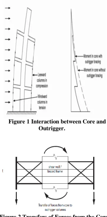
High rise structures are designed to improve building overturning stiffness and strength by connecting outriggers to the building core to distant columns and outriggers are nothing but rigid horizontal structure. Outriggers have been used in tall, narrow buildings for nearly half a century, but the design principle used for millennia. The explanation of outrigger behavior is simple: because outriggers act as stiff-arm engaging outer columns. When the structure is subjected to horizontal loading, shear wall and outrigger trusses will rotate and its rotation induces a tension-compression couple in the outer columns acting in opposing to the movement. As a result, is a type of restoring moment acting on the core at that level. Analysis and Design of a complete core and outrigger system are quite completed as relative stiffness of each element responsible for the distribution of forces between the core and the outrigger system. So it is difficult to arbitrarily assign overturning forces to the core and the outrigger column. It is certain that bringing
perimeter structural elements together with the core as one lateral load resisting system then it will reduce core overturning moment, but not effective in reducing core horizontal shear forces. (See figure 1 and 2)
Figure 1 Interaction between Core and Outrigger.
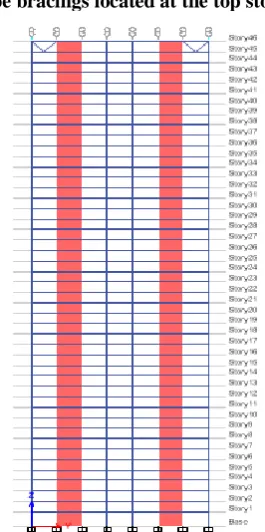
Figure 2 Transfers of Forces from the Core to Column.
outriggers connected individual mega column, belt truss can transfer more gravity load to the mega column to minimize net uplift. Reinforcement or the column splices can be used to reduce tension and stiffness reduction associated with concrete in net tension. Belt truss can further enhance overall building stiffness through virtual or direct outrigger behavior provided high in-plane shear Stiffness, As well as increasing tower torsional stiffness for both mega column and tube building. Belt working with the mega column can also create a secondary lateral load resisting system in seismic resisting technology. A core and outrigger system is frequently selected for lateral load resisting system of all tall or slender building where the overturning moment is large compared to shear, and where overall building flexural deformations are major contributors to lateral deflection such as story drift. In that case, building drift and core wind moments reduced due to outriggers. The outrigger system is a very efficient and cost-effective solution to reduce building accelerations, because of the increased stiffness they provide, which improves occupant comfort during high winds.
II. OBJECTIVES
1. To study the behavior of high rise RCC building
structure provided with steel outriggers along with belt truss system subjected to seismic forces.
2. To study the parameters such as lateral
displacement, story drift, base shear with steel outriggers with X-type and V-type bracing systems of high rise RCC structure using by linear and non-linear methods of analysis as per the guidelines of IS 1893-2016.
3. To compare the reduction in displacement with
the increase in base shear for the increase in the number of outriggers.
III.METHODOLOGY
The model considered for this study is a 139m high rise reinforced concrete building frame. The Plan area of the Structure is 42m x 42m with columns spaced at 6m from the center to center. The height of the bottom story is 4m and all other floors are of height 3m considered as typical floors. Shear wall thickness is considered as 300 mm over the entire height. Beams 300mm wide and 750 mm deep, column 450 mm x 600 mm, the thickness of slab 200mm and Grade 40 (Mix – M40) concrete and steel Outriggers of steel tube section of size 400 x 400x 25mm of is considered throughout the height of the building.
The study is performed for seismic zones V as per IS 1893 (Part1): 2016. The Importance factor is considered 1.5 for the structure. The analyses are based upon the assumptions that the outriggers are pinned attached to the core; Neglecting soil-structure interactions (fixed supports) for all columns and core.
The Linear and Non-Linear analyses are carried out using ETABS software. The plan and elevation of the structure as shown in the figure below (fig 3 & 4)
Fig-3 Plan of G+45 Stories Conventional Building.
Figure 5 Details of Outriggers in perspective view.
Event name: Imperial Valley
Year of occurrence: 1979
Magnitude: 6.53
Peak ground acceleration: 0.45
Recording station: Array 06-01
Figure 6 Imperial Valley ground acceleration
Different Arrangements of Outriggers The models that are selected for the study are listed as follows,
1. Conventional frame model without
outriggers.( Figure 3 & 4)
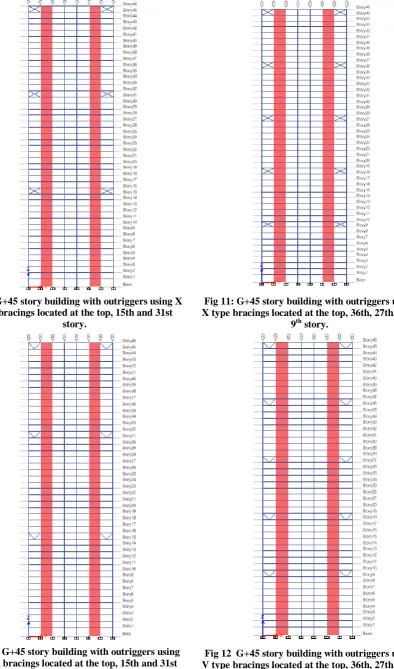
2. Model with V-type braced outriggers
located at the top story. (Figure 8)
3. Model with X-type braced outriggers
located at the top story. (Figure 7)
4. Model with V -type braced outriggers
located at the top, 15th and 31st story. ( top,
1/3rd, 2/3rd ) (Figure 4.4)
5. Model with X-type braced outriggers
located at the top, 15th and 31st story. ( top,
1/3rd, 2/3rd ) ((Figure 4.5)
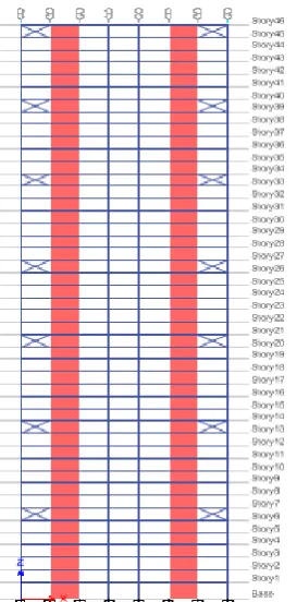
6. Model with V-type braced outriggers
located at the top, 36th, 27th, 18th, 9th story. (top, 1/5th,2/5th,3/5th, 4/5th) (Figure 4.6)
7. Model with X-type braced outriggers
located at the top, 36th, 27th, 18th, 9th story. (top, 1/5th,2/5th,3/5th, 4/5th) (Figure 4.7)
8. Model with V-type braced outriggers
located at the top, 39th, 33rd,26th, 20th, 13th, 6th story. (top, 1/7th, 2/7th, 3/7th, 4/7th, 5/7th,
6/7th ) (Figure 4.8)
9. Model with X-type braced outriggers
located at the top, 39th, 33rd, 26th, 20th, 13th, 6th story (top, 1/7th, 2/7th, 3/7th, 4/7th, 5/7th,
6/7th ) (Figure 4.9)
Fig 7: G+45 story building with outriggers using X type bracings located at the top story.
Fig 9: G+45 story building with outriggers using X type bracings located at the top, 15th and 31st
story.
Fig 10: G+45 story building with outriggers using V type bracings located at the top, 15th and 31st
story.
Fig 11: G+45 story building with outriggers using X type bracings located at the top, 36th, 27th, 18th,
9th story.
Fig 12 G+45 story building with outriggers using V type bracings located at the top, 36th, 27th, 18th,
Fig 13: G+45 story building with outriggers using X type bracings located at the top, 39th, 33rd,26th,
20th, 13th, 6th story.
Fig 14: G+45 story building with outriggers using V type bracings located at the top, 39th, 33rd, 26th,
20th, 13th, 6th story.
IV.RESULTANDDISCUSSION
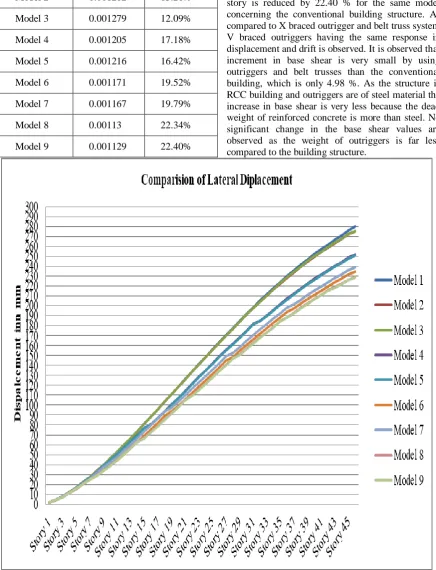
1. Lateral displacements:
Maximum roof displacement is one of the most important criteria for locating outrigger–belt truss system optimally. Story displacement is the absolute value of displacement of that story under the action of lateral force. The maximum displacement of all models at the top story and percentage reduction in displacements as compared to conventional building using linear and Non-linear analysis are given below table 1 and respectively.
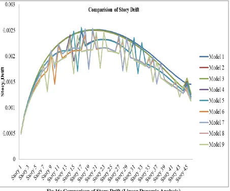
2. Story Drift:
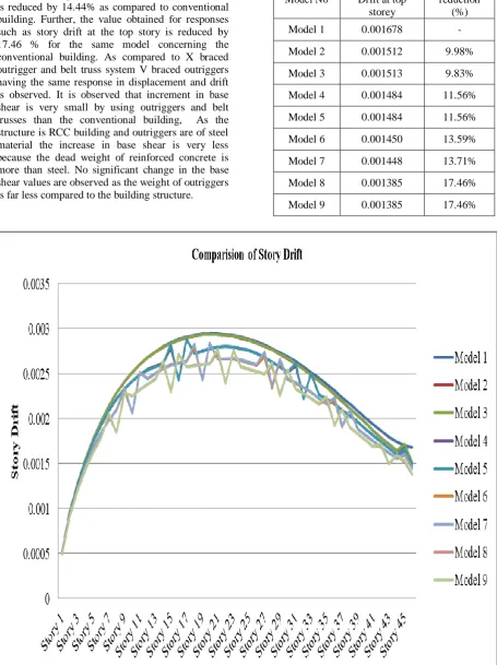
Story drift is the difference of displacement between two consecutive stories dived by the height of that story. The maximum story drift of all models at the top story and percentage reduction in the drift as compared to conventional building using linear and Non-Linear analysis are given below table 2 and 5 respectively.
3. Base shear:
Base shear is the maximum expected lateral force that will occur due to earthquake ground motion at the base of a building structure. Base shear of all the models is computed from the linear and non-linear method of Analysis are shown below in table 3 and table 6 respectively.
Table 1 Maximum lateral displacement by linear Dynamic Analysis
Model No
Maximum displacement at
top story (mm)
Percentage reduction (%)
Model 1 279.793 -
Model 2 274.936 1.73%
Model 3 275.202 1.64%
Model 4 251.381 10.15%
Model 5 250.529 10.45%
Model 6 234.675 16.12%
Model 7 238.68 14.69%
Model 8 228.571 18.31%
Table 4 Maximum Lateral Displacement by
Non-linear Time-History Analysis From the graph given below, it is observed that the
displacement of RCC structure provided with an outrigger system with X braces along with belt trusses at the top, 39th, 33rd, 26th, 20th, 13th, and the 6th story is reduced by 18.47% as compared to the conventional building. Further, the value obtained for responses such as story drift at the top story is reduced by 22.40 % for the same model concerning the conventional building structure. As compared to X braced outrigger and belt truss system V braced outriggers having the same response in displacement and drift is observed. It is observed that increment in base shear is very small by using outriggers and belt trusses than the conventional building, which is only 4.98 %. As the structure is RCC building and outriggers are of steel material the increase in base shear is very less because the dead weight of reinforced concrete is more than steel. No significant change in the base shear values are observed as the weight of outriggers is far less compared to the building structure.
Fig 15: Comparison of lateral displacement (Linear Dynamic Analysis) Model No
Reduction in
Drift at top storey
Percentage reduction (%)
Model 1 0.001455 -
Model 2 0.001262 13.26%
Model 3 0.001279 12.09%
Model 4 0.001205 17.18%
Model 5 0.001216 16.42%
Model 6 0.001171 19.52%
Model 7 0.001167 19.79%
Model 8 0.00113 22.34%
Fig 16: Comparison of Story Drift (Linear Dynamic Analysis
)
Table
3 Maximum Base shear from linearDynamic Analysis
Table 4 Maximum Lateral Displacement by Non-linear Time-History Analysis
Model No
Maximum displacement at
top storey (mm)
Percentage reduction (%)
Model 1 324.738 -
Model 2 321.165 1.00%
Model 3 321.291 0.95%
Model 4 304.51 6.12%
Model 5 304.468 6.14%
Model 6 291.651 10.01%
Model 7 291.759 10.01%
Model 8 277.636 14.41%
Model 9 277.538 14.44%
Model No Maximum base shear
(KN)
Model 1 18310.144
Model 2 18334.427
Model 3 18348.539
Model 4 18382.993
Model 5 18425.329
Model 6 18508.710
Model 7 18494.652
Model 8 19088.646
The results obtained by Non-linear time history analysis are shown in the graph below, it is observed that the displacement of RCC structure provided with outrigger system with X braces along with belt trusses at the top 39th,33rd, 26th, 20th, 13th, 6th stories is reduced by 14.44% as compared to conventional building. Further, the value obtained for responses such as story drift at the top story is reduced by 17.46 % for the same model concerning the conventional building. As compared to X braced outrigger and belt truss system V braced outriggers having the same response in displacement and drift is observed. It is observed that increment in base shear is very small by using outriggers and belt trusses than the conventional building, As the structure is RCC building and outriggers are of steel material the increase in base shear is very less because the dead weight of reinforced concrete is more than steel. No significant change in the base shear values are observed as the weight of outriggers is far less compared to the building structure.
Table 5 Reduction in Drift by Non –Linear Time History Analysis
Fig 18: Comparison of Story Drift (Linear Dynamic Analysis Model No
Reduction in Drift at top
storey
Percentage reduction
(%)
Model 1 0.001678 -
Model 2 0.001512 9.98%
Model 3 0.001513 9.83%
Model 4 0.001484 11.56%
Model 5 0.001484 11.56%
Model 6 0.001450 13.59%
Model 7 0.001448 13.71%
Model 8 0.001385 17.46%
Table 6 Maximum Base shear from Non-linear Time-History Analysis
V. CONCLUSION
This paper focuses on the seismic behaviour of tall structure with outriggers and belt truss system using Linear dynamic and Non-Linear Time History Analysis from which the following conclusion can be drawn based on the above result:
1. From the linear and non-linear analysis of
the RCC building provided with the outrigger systems using X and V type bracing, it is observed that both types of outrigger system having the nearly same response and X braced system is barely effective than V type bracings as are giving minimum displacement and drift values.
2. In the linear dynamic analysis of the RCC
building, provided with an outrigger system with X type bracings, the lateral displacement and top story drift get reduced by 18.47% and 22.40% respectively compared to the values obtained from the analysis of conventional RCC building. However, in the non-linear method of analysis, lateral displacement and top story drift get reduced by 14.44% and 17.46% respectively compared to the values obtained from the analysis of conventional RCC building.
3. The complete comparative analysis reveals
that to know the behaviour of the tall structure under earthquake loadings, time history analysis must be performed as it gives more response to time history analysis as compared to Linear Dynamic Analysis.
REFERENCES
[1] Han-Soo Kim, Hye-Lym Lee, You-Jin Lim,
“Multi-objective optimization of dual-purpose outriggers in tall buildings to reduce lateral displacement and differential axial shortening”, ScienceDirect, Engineering Structures, 189(2019), P-296-308.
[2] Dilrukshie I. Samarakkody, David P. Thambiratnam,
Tommy H. T. Chan, Praveen H. N. Moragaspitiya, “Outrigger belt and frame interaction in composite tall buildings under differential axial shortening”, ASCE, Journal of Architectural Engineering, 23(3)(2017), P-1-14 [3] Meisam Safari Gorji, J. J. Roger Cheng, “Steel plate shear
walls with outriggers. Part II: Seismic design and
performance”,ScienceDirect, Journalof constructional steel
research, 37(2017), P-127-145.
[4] E. Bunesi, R. Nascimbene, L. Casagrande, “Seismic
analysis of high-rise mega-braced frame-core buildings, ScienceDirect, Engineering Structures”, 115(2016), P1-17.
[5] Osama Ahmed Mohmed, Omar Najm, “Outrigger systems
to mitigatedisproportionate collapse in building structures”,
ScienceDirect, Procedia engineering, 161(2016), 839-844.
[6] Kang Zhou, Xiao-Wei Luo, Qiu-Sheng Li, “Decision
framework for optimal installation of outriggers in tall
buildings”, ScienceDirect, Automation in Construction,
93(2016), P-200-213.
[7] Patil Dhanaraj M., Sangle Keshav K., Seismic behavior of
different bracing systems in high-rise 2-D steel buildings, ScienceDirect, Structures, 03(2015), 282-305.
[8] Shivacharan K, Chandrakala S, Karthik N M, “Optimum
Position of Outrigger System for Tall Vertical Irregularity Structures”, IOSR Journal of Mechanical and Civil Engineering, Volume 12, Issue 2 Ver. II (Mar - Apr. 2015), PP 54-63.
[9] Dr. S. A. Halkude, Mr. C. G. Konapure and Ms. C. A.
Madgundi, “Effect of Seismicity on Irregular Shape Structure”, International Journal of Engineering Research & Technology (IJERT) Vol. 3 Issue 6, June – 2014.
[10] Panchal Dhara, Sharad Purohit, “Dynamic Response Control
of a Building Model using Bracings, ScienceDirect,
Procedia engineering”, 51(2013), 266-273.
[11] A., D. Yahiaoui, Seismic assessment of braced RC frames,
ScienceDirect, Engineering Structures, 14(2011), P-2899-2905.
[12] N. Herath, N. Haritos, T. Ngo, P. Mendis, “Behavior of Outrigger Beams in High rise Buildings under Earthquake
Loads”, Australian Earthquake Engineering Society,
Newcastle, June-2009.
[13] Willford M. R., R. J. Smith, “Performance based seismic
and wind engineering for 60 storey twin towers in manila”, World conference on earthquake engineering, Bejing, China, October-2008
[14] Agarwal Pankaj, Manish Shrikhande (2006), Earthquake
Resistant Design of Structures, PHI publications, New Delhi, India.
[15] Duggal S. K. (2013), Earthquake Resistant Design of
Structures, Oxford University Press, New Delhi, India. [16] IS 1893 Part 1 (2016), Criteria for earthquake resistant
design of structures, Bureau of Indian Standards, New Delhi, India.
Model No Maximum base shear
(KN)
Model 1 17418.519
Model 2 17426.404
Model 3 17430.986
Model 4 17442.173
Model 5 17455.919
Model 6 17457.942
Model 7 17480.159
Model 8 17473.711