STUDY OF DYNAMIC DRAPE
BEHAVIOUR OF FABRIC USING FEM
Part I: Model Formulation and Numerical Investigations
HASSEN HEDFI
University of Monastir, National Engineering School, Mechanical Engineering Laboratory Ibn Aljazzar Street, Monastir 5019, Tunisia
[email protected] ADEL GHITH
University of Monastir, National Engineering School, Thermal and Energetic Systems Studies Laboratory Ibn Aljazzar Street, Monastir 5019, Tunisia
[email protected] HÉDI BEL HADJ SALAH
University of Monastir, National Engineering School, Mechanical Engineering Laboratory Ibn Aljazzar Street, Monastir 5019, Tunisia
Abstract:
This article presents a study of textile fabric drape by using the finite element method (FEM). The objective of this work is to bring useful information concerning the nature of phenomenon of drape and to find a better manner of modelling the drape behavior. The fabric is regarded as an orthotropic medium. A numerical and parametric study of the drape behavior is then carried out. Finite Element Model formulation and the influences of the discretization in finite elements are treated in this first part. Mesh element type, density and shape are studied. Membrane element can’t simulate accurately the bending of fabric unlike shell element which is more appropriate to fit this type of deformation occurred when fabric is draped. Refinement of mesh can improve the realism of simulation but too fine meshes become very costly in terms of CPU time. The effects of certain physical and mechanical parameters on drape simulation form the focus of second part of this paper.
Keywords: Woven fabric; drape; finite element method; dynamic behavior; stability
1. Introduction
The modeling and the simulation of textile fabrics represent an important field of scientific research. Several disciplines intervene in this field: mathematics, mechanics, physics, and informatics. This activity of research aims to producing simulations of textile fabrics behavior with more realism while remaining faithful to the physical and mechanical properties of this type of materials. The fabrics are complexes structures obtained by the interlacing of two sets of wire forming two privileged directions: the warp direction and the weft direction. The manner with which these two sets of wire are intersected is called weave pattern. The textile fabrics are characterized by a great aptitude to become deformed even under low constraints. Drape, capacity of fabrics to become deformed more or less amply under the effect of their weight, is one of the most required characteristics for clothing and for furnishing applications. The drape behavior is typically a large deformation but small strain problem [Liu and Sze, 2009]. Fabric drape is often studied and several papers are devoted to the modeling and to the numerical simulation of the fabric drape behavior.
drape coefficient on shear angle (A), A2, bending length (c) and c2 are calculated. Regression equations obtained confirmed the dependance of drape coefficient on the shear stiffness in addition to the bending length. Morooka
et al., [Morooka et al., 1976] used the drape coefficient to characterize the drape-ability of fabrics and investigated the relations between this coefficient and some measured mechanical properties. Residual-regression and multiple Residual-regression methods have been used to find correlations between drape coefficient and bending rigidities (in warp, weft and bias directions) and weight per unit area of fabric. The influence of the anisotropy in bending rigidity on the drape prediction was studied. The effect of the hysteresis in fabric shearing and bending on the drape coefficient stability and reproducibility had been also investigated. It is shown that more the hysteresis in fabric shearing and bending is large, more the stability and reproducibility in the drape coefficient are small. Hearle & Amirbayat [Hearle & Amirbayat, 1986] and Amirbayat & Hearle [Amirbayat & Hearle, 1989] analysed the buckling behaviour of textile fabrics and demonstrated the effect of this proporty on the drape and the aesthetic appearance of fabrics. The authors related the drape coefficient of fabric to two dimensionless energy groups J1 and J2, which relate to bending, membrane, and potential energies. They affirmed that a more complex relationship existed between physical and mechanical proporties of fabric and their drapability. For those authors, the drape coefficient is also influenced by other parameters such as the full set of anisotropic in-plane membrane and out-of-plane bending and cross-term elastic constants. The nonlinearity of fabric drape response should also be regarded. Collier, et al. [Collier, et al., 1991] used the finite element method for fabric drape prediction. Woven fabrics were modelled as an orthotropic shell membrane. Measured material properties such as tensile moduli, in warp and weft direction, and Poisson’s ratio were used to fit the finite element model. Drape coefficients of some plain weave fabric obtained from the finite element modelling were compared with experimental ones which had been measured using a drape tester designed and constructed by those researchers. This work had the importance to initiate the use of the finite element method for modeling and the prediction of the mechanical behaviour of fabrics. More recent works are also very useful for the comprehension of the textile fabric drape phenomenon. Chen & Govindaraj [Chen & Govindaraj, 1995] presented a model based on the flexible shell theory to simulate fabric drape. The authors used mechanical properties such as tensile and shear modulus to predict fabric drape behavior numerically. Simulations presented seem to be convincing. The authors used this model to carry out a parametric study of the drape behavior [Chen and Govindaraj, 1996]. This investigation aimed to study the influence of certain parameters such as the orthotropy, Young modulus, shear modulus, Poisson's ratio, surface mass density and thickness on fabric drape behavior. In spite of its qualitative character, this study is significant insofar as it makes possible to identify the dependence of drape to mechanical and physical properties of fabrics. Gan et al. [Gan et al., 1995] used non linear finite elements to analyze the textile fabrics deformations. In this formulation the geometrical non linearity is investigated and fabric deformations are presented as a phenomenon that involves large displacement and large rotation under small strain. In this investigation the fabrics are modeled by shell / plate elements. Results of simulations are compared with experimental ones and seem to be closer to them. Jeffrey et al. [Jeffrey et al., 1996] used nonlinear shell theory to model and to control flexible fabric. Their purpose was to simulate 3D motions related to real fabric-manufacturing processes and to make possible the automation of the textile and apparel industries.
For all caused works, only the static drape was studied. However, the dynamic aspect of the phenomenon of drape started to arouse the interest of several researchers. Stylios et al. [Stylios et al., 1996] explored the modelling of dynamic drape for garments simulation in virtual fashion show. A deformable node-bar model based on physical concept analogue to the shell formulation was developed and used to predict the deformation of fabric garments. Results presented cover circular fabric draped over circular pedestal and short and long skrit draped over virtual mannequin. Stylios & Zhu [Stylios & Zhu, 1997] tried to establish a standard characterization of the static and dynamic drape. The original contribution reported in this work was the using of three parameters, defined by the feature vector, to characterize objectively the static and dynamic drape behaviour. Those parametrs are: the average of the maximum fold’s lengths, ρmax, the average of the minimum fold’s depths, ρmin, and the parameter S indicating the distribution of the folds. A digital image processing based drape-meter was developed and used in this study. This series of papers was ended by an article [Stylios & Wan, 1999] introducing the concept of virtual measurement for fabric, especially the virtual characterization of fabric drapeability. Frydrych et al. [Frydrych et al., 2000] investigated the mechanical fabric properties that influence the drape and handle. The authors tried to find better linear correlation between drape coefficient and some measured mechanical properties like bending rigidity, initial tensile modulus, fabric weight and fabric formability. It was found that the bending rigidity in the weft direction, initial tensile modulus in warp direction and fabric formability in weft direction have more significant influence on the fabric drape. The influence of the anisotropy can be intuitively concluded from the differences between the effect of mechanical properties measured in warp and weft directions on the drape simulations. Several other papers are dedicated to the simulation and the study of fabric drape. In which was used the finite element method [Hu, et al., 2000; Hearle,
element method on a regular grid for simulation of textile fabrics drape. In [Liu & Sze, 2009] we note a significant evolution in the control of the numerical tool to simulate the static and dynamic behavior of textile fabrics draped over objects having very variable geometrical forms. In [Li & Zhang, 2008], the authors used the finite element method to simulate draping and buckling of woven fabric and knitted fabric under gravity load, and studied the difference between them. The authors are interested to the micro-mechanical models of woven fabric and knitted fabric to characterize the special properties of fabric due to their structures.
2. Methods and Materials
In this section, we introduce the methods and materials used in this investigation. 2.1.Characterization of fabrics
2.1.1. Mechanical Characterization
The mechanical characterization of textile fabrics aims to determine the mechanical properties of these structures in order to know their abilities and performance for specific applications. This characterization will serve as a starting point to describe the mechanical behavior and modeling of textile fabrics. The modeling of woven fabrics enables to simulate their behavior, their aesthetic appearance, their drapability and their fallen. Among the mechanical properties that we can study, we quote:
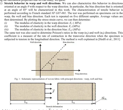
(1) Stretch behavior in warp and weft directions. We can also characterize this behavior in directions oriented at an angle θ with respect to the warp direction. In particular, the bias direction that is oriented at an angle of 45° will be characterized in this work. The characterization of tensile behavior is performed according to French standard NF G07-001. The test was performed on specimens cut in the warp, the weft and bias direction. Each test is repeated on five different samples. Average values are then determined. By plotting the stress-strain curve, we can then determine:
(i) The modulus of elasticity in the warp direction: E1 ( MPa)
(ii) The modulus of elasticity in the weft direction: E2 (MPa)
(iii) The modulus of elasticity in the direction bias: E45 (MPa)
The same test was also used to determine Poisson's ratios in the warp (υ1) and weft (υ2) directions. This coefficient is a measure of the rate of contraction in the transverse direction when the specimen is subjected to tension in the longitudinal direction. The method is well explained in [Hedfi et al., 2011]
Fig. 1 : Schematic representation of woven fabric with principal directions : warp, weft and bias
Fig. 2 : Fabric stretch deformation (in warp direction), Fis loading force, L0is the fabric initial length and L0is the warp fabric elongation
The modulus of rigidity H is computed using the following formula (Saville, 1999, pp: 272). 1
2 1
45 1 2
1 1
4
H
E E E
(2)
Where E1, E2 and E45 are the Young's moduli in the warp, weft and bias directions and ν1 and ν2 are the fabric Poisson's ratios.
Fig. 3 : Fabric shear deformation, Fis loading force, is the shear angle
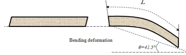
(3) Bending behavior. Characterization of bending behavior of textile fabrics is made using the Cantilever test according to the ASTM standard D1388 (Standard Test Method for Stiffness of Fabrics). The test is performed on fabrics samples in the warp, weft and bias direction. The dimensions of each sample are
200 mm by 25 mm. The test was repeated on five different samples for each direction. Average values of falling length L are then determined. We can compute bending stiffness as:
3 cos 0.5 6
9.807 10
8 tan
i i
Rf L
(2)
Where, Rfiis the bending rigidity in warp (i=1), weft (i=2) and bias (i=45) direction, Lithe length of fabric hanging under effect of its own weight until reaching a plan inclined at an angle θ=41.5°, and ρ
is the fabric surface density.
Fig. 4 : Fabric bending deformation, Lis the falling length
2.1.2. Physical Characterization
(1) Fabric surface density. Determining the surface density of a fabric is made by cutting a sample of fixed area and weighs it using a precision balance. The test is performed at least on five samples. An average weight is calculated. This measurement is carried out according to international standard ISO 3801-1977.
(2) Fabric thickness. The thickness of a fabric is one of the most important characteristics. Although small, even negligible compared to the size of a fabric or a made-up article, this dimension determines the flexibility and deformability of textile fabrics. The measurement principle is as follows: compressing a sample of fabric between two plates by applying a defined pressure, the thickness of the fabric is then equal to the value of the spacing between the two plates. The thickness is denoted δ. The ASTM Standard (ASTM D 1777– 96) specifies a pressure of4,14 0, 21 kPa.
2.2.Problem formulation
In this section, we develop a model of textile fabrics. This model is based on:
(1) The general formulation of deformable models introduced by Hedfi et al. [Hedfi et al., 2011]
(2) The finite element method implemented for the resolution of Partial Differential Equations (PDE) governing the dynamic behavior of textile fabrics.
2.2.1. The equation of motion of textile fabrics
The equation of motion of the surface of the textile fabric can be formulated as follows: 2 int 2 ext r r f f t t (3) Where,
: The surface density (kg m-2) : The damping density (Kg m-2 s-1)
r
: The vector of instantaneous position of a point P belonging on the fabric surface. We haver r a a t
1, ,2
,
21, 2
a a denote the parametric variables, defined on parametric domain 2 R2, and tindicate the time. int
f
: The internal elastic forces resulting of the deformation occurred in the fabric during motion or when interacting with other solid object or with fluid flow.
ext
f
: The external forces such as gravitational forcefg g, ggravitational acceleration.
2.2.2. Internal elastic forces
These forces are defined using tow surface tensor: metric tensor G and curvature tensor B. It can be derived from internal energy densities using a variational formulation. Tow internal energy densities can be defined [Au
et al. 2000]
(1) Internal energy density due to stretch-shear deformation S:
0
0
1 8 S
S
C G G G G
(4)
In this equationCS denote the materials coefficients describing its stretch-shear behavior and
G(respectivelyG0 ) coefficients of metric tensor of the fabric surface in current configuration t>0 (respectively in initial configuration t=0)
, , 1, 2r r G a a (5.a)
0 00 r r , , 1, 2
G a a (5.b)
(2) Internal energy density due to bending-twist deformation B:
0
0
1 2 B
B
C B B B B
(6)
In this equationCB denote the materials coefficients describing its bending-twist behavior and
B(respectivelyB0 ) coefficients of curvature tensor of the fabric surface in current configuration t>0 (respectively in initial configuration t=0)
2, , 1, 2
r B n a a (7.a)
2 00 0 r , , 1, 2
B n a a (7.b) Where n(respectivelyn0) is the unit normal vector of the fabric surface in current configuration t>0 (respectively in initial configuration t=0).
1 2 1 2
r r r r
n
a a a a
(7.c)
Internal forces are then deduced as:
int S B
S B
f CεεCκκ
0
1
2 G G
(9.a)
And κdenotes the Green’s bending strain tensor: 0
B B
(9.b)
2.2.3. Constitutive behavior law
We consider that the behavior of the textile material is elastic obeying Hooke's law. Two components are considered:
(1) The in-plane behavior described by the following relation between in-plane strain () and membrane
stress (N) 2 11 1 2 11 22 1 22
1 2 12
12 1 0 1 0 2 1 0 0 E E N N E E N H (10)
We can deduce:
1111 1 1122 2211 2 1 2222 2 1212
1 2 1 2 1 2
, , ,
1 1 1
S S S S S
E E E
C C C C and C H
(11.a)
2 2
0 0 0 0
1 11 11 2 22 22 2 1 11 11 22 22
2 0 1 2
1 2 12 12
2 1
8 1 4 1
S E G G E G G E G G G G
H G G
(11.b)
(2) The out-of-plane behavior described by the following relation between out-of--plane strain () and
bending stress (M)
11 1 11 22 22 2 12 12 1 0 0 1 0 0 2
0 0 0
Rf N N Rf N (12)
We assumed that the fabric does not undergo twist deformation. We can deduce:
1111 2222
1 2
B B
C Rf and C Rf (13.a)
0
2
0
21 11 11 2 22 22
B Rf B B Rf B B
(13.b)
3. Results and discussions: the influence of numerical computation’s parameters 3.1. Mesh element type
Two different elements are studied:
(1) The membrane element has a structure where one dimension is small compared to others; it is generally used to describe the in plane behavior. It is considered as incapable to reproduce out-of- plane strain. (Fig. 5-a)
Fig. 5 : element type (a) membrane and (b) shell element
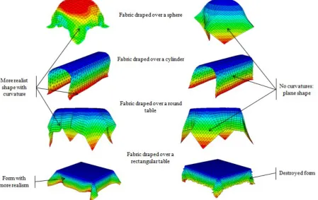
To test the ability of each of these two elements for textile fabrics meshing, simulations on different support (sphere, cylinder, rectangular table and round table) are made using both types of elements (Fig. 6).
Fig. 6: influence of mesh element type, (right) membrane and (left) shell element
The most remarkable result that can be drawn is that the membrane element, unlike the shell element, can’t reproduce the proper curvature. Indeed, we note that the membrane element is not able to reproduce the curvature of the support, however small, as the case of the cylinder.
In cases where many bends occur, it was found that the membrane element gives:
(i) A rigid plate shape: to simulate a high curvature as the case of the sphere (compare Fig. a and Fig. 7-b)
(ii) Accordion shape: to simulate the rendering of several small curvatures as the case of the circular table (compare Fig. 7-c and Fig. 7-d)
Fig. 7 : Natural shape obtained with shell element when draping fabric over (a) sphere, and (c) round table; (b) A rigid plate shape obtained with membrane element when draping fabric oversphere and (d) accordion shape obtained with membrane element when draping fabric
round table
Fig. 8: Excessive membrane mesh distortion
In reality, the element should be curved. This deformation induces an unrealistic artificial rigidity of the element, something that deepens its inability to represent this type of physical loading (bending). This problem can be treated using quadratic interpolation functions. Indeed, adding more nodes per element can better approximate the deformations because these functions allow the element to bend as shown in Fig. 9:
Fig. 9: Using element with many nodes approximates accurately complexes deformation (bending and shear)
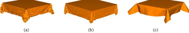
The same idea (use more nodes) let us consider adopting a finer mesh to minimize the distance between nodes and ensure a better approximation of curvature. To test this idea, we simulate the case of fabric draped over rectangular table with a much finer mesh and we got the following result (Fig. 10)
Fig. 10: Fabric draped over rectangular table meshed with (a) membrane element (coarse mesh), (b) membrane element (fine mesh), and (c) shell element with the same fine mesh as case (b)
We see that after mesh refinement, we were able to overcome or at least reduce this unwanted distortion of the membrane mesh (Fig.10-a). Nevertheless, the new acquired form (Fig.10-b) is not so realistic especially when compared with that obtained by the shell element (Fig. 10-c) even when adopting the same mesh density. This result confirms the non adaptation of the membrane element to modeling the draping behavior of woven fabric, because bending stresses are greatly involved. Furthermore, we drew attention to the influence of mesh density on the results of simulation. The next section devoted to study this parameter.
3.2. Mesh density
To better see the influence of mesh density on the simulation result of draping behavior, we varied the number of used elements from 625 to 30276 elements while recording the CPU time for each case. The results found (Fig. 11) show that over the mesh is refined over the simulations are accurately and realist. CPU time increases exponentially with the number of nodes (Fig. 12). This leads us to seek optimal mesh refinement that gives us a satisfactory result in reasonable time. The case of Fig. 10-d for example, may meet this criterion with a relatively fine mesh (5184 elements) and a practically acceptable CPU time (1h 2’). Furthermore we do not see a great difference (from the point of view of the drape shape) between this result and those found in the cases of Fig.10-e-f where we have used a finer mesh (10000 and 30276 elements) although they are much more expensive in CPU time (5h 06’ 02’’ and 10h 18’).
Fig. 11 : Variation of element number for simulation of fabric draped over rectangular table using shell elements
Fig. 12 : CPU-time variation as a function of element numbers
3.3.Mesh element shape
To check if the shape of the element may also influence the simulation results, we replaced the quadrilateral shell element used previously by triangular shell element while retaining the same number of elements. (Fig. 13)
Fig. 13 : Mesh element shape
Fig. 14 : Results obtained for simulations of woven fabric draped over rectangular table using triangular and quadrilateral element
Figure 14 illustrates the results found. In fact, we do not notice a great difference between the two simulations except for CPU time which is slightly larger in the case of the triangular element (CPU=1h 40’) than that in the quadrilateral (CPU=1h 2’). This may be due to the complexity of the interpolation function in the case triangular element. But it should be noted that this element type presents a valuable advantage; that it greatly reduces the problem of distortion of the mesh.
4. Conclusion
(1) It is more convenient to use shell element to model the dynamic behavior of the fabric because the membrane element is unable to fit accuracy bending deformation that the fabric acquired during the draping
(2) We must use a sufficient number of elements that can give a realist simulation in a reasonable time, and for more precision, we can use quadratic interpolation functions.
(3) The choice of element shape is not very influencing parameter but the triangular element can be very useful to overcome mesh distortion problems.
The second part of this paper will deals with the influence of texture parameters on the dynamic behavior of textile fabrics. We will discuss mainly the effect of physical, and mechanical parameters, as well as construction parameters of the textile fabric.
5. References
[1] Liu, X. H., & Sze, K. Y. (2009). A corotational interpolatory model for fabric drapes simulation. International journal for numerical methods in engineering, 77, 799-823.
[2] Chu, C. C., Cummings, C. L., & Teixeira, N. A. (1950). Mechanics of Elastic Performance of Textile Materials: Part V: A Study of the Factors Affecting the Drape of Fabrics—The Development of a Drape Meter. Textile Research Journal, 20 (8), 539-548.
[3] Cusick, G., E. (1965). The dependence of Fabric drape on bending and shear stiffness. The Journal of textile Institute, 56. 596-606. [4] Morooka, H., & Niwa, M. (1976). Relation between Drape Coefficients and Mechanical Properties of Fabric. Journal of the Textile
Machinery Society of Japan, 22 (3), 67-73.
[5] Hearle J. W. S., Amirbayat J. (1986). Analysis of drape by means of dimensional group, Textile Research Journal, 56, 727-733. [6] Amirbayat, J., and Hearle, J., W., S. (1989). The Anatomy of Buckling of Textile Fabrics: Drape and Conformability. Journal of the
Textile Institute, 80, 52–70.
[7] Collier, R., Collier, B., J. (1991). Drape Prediction by Means of Finite Element Analysis, Journal of Textile Institute, 82, 96-107. [8] Chen, B., & Govindaraj, M. (1995). A Physically Based Model of Fabric Drape Using Flexible Shell Theory. Textile Research
Journal, 65 (7), 324-330.
[9] Chen, B., & Govindaraj, M. (1996). A Parametric Study of Fabric Drape. Textile Research Journal, 66 (1), 17-24.
[10] Gan, L., Ly, N. G., & Steven, G. P. (1995). A Study of Fabric Deformation Using Nonlinear Finite Elements. Textile Research Journal, 65 (11), 660-668.
[11] Jeffrey, E., Shigan, D., & Timothy, G. C. (1996). Finite- element modeling and control of flexible fabric parts. IEEE Computer Graphics and Applications, 16 (5), 71-80.
[12] Stylios, K. G., Wan, T. R., & Powell, N. J. (1996). Modelling the dynamic drape of garments on synthetic humans in a virtual fashion show. International Journal of Clothing Science and Technology, 8 (3), 95-112.
[13] Stylios, G., K., & Zhu, R. (1997). The Characterization of the Static and Dynamic Drape of Fabrics. Journal of Textile Institute, 88, 465-475.
[14] Stylios G., Wan T. R. (1999). The Concept of Virtual Measurement. International Journal of Clothing Science and Technology, 11(1), 10-18
[15] Frydrych, I., Dziworska, G., & Cieslinska, A. (2000). Mechanical Fabric Properties Influencing the Drape and the Handle. International Journal of Clothing Science and Technology, 12 (3), 171-183.
[16] Hu, J., Chen, S.-F., & Teng, J. G. (2000). Numerical Drape Behavior of Circular Fabric Sheets over Circular Pedestals. Textile Research Journal, 70 (7), 593-603.
[17] Hearle, J. W., Potluri, P., & Thammandra, V. S. (2001). Modelling Fabric Mechanics. The Journal of Textile Institute, 92 (3), 56-69. [18] Lo, W. M., Hu, J. L., & Li, L. K. (2002). Modeling a Fabric Drape Profile. Textile Research Journal, 72 (5), 454-463.
[19] Jevsnik, S., Gersak, J., & Gubensek, I. (2005). The advance engineering methods to plan the behaviour of fused panel. International Journal of Clothing Science and Technology, 17 (3/4), 161-170.
[20] Xiaolin, M., & Collby, C. S. (2007). A Mathematical Modeling Framework for Analysis of Functional Clothing. Journal of Engineered Fibers and Fabrics, 2 (3), 10-28.
[21] Chen, S. F., Hu, J. L., & Teng, J. G. (2001). Finite-volume methods for contact drape simulation of woven fabrics and garments. Finite Elements in Analysis and Design, 37, 513-531.
[22] Sze, K. Y., & Liu, X. H. (2003). A co-rotational grid-based model for fabric drapes. International Journal for Numerical methods in Engineering, 57, 1503–1521.
[23] Sze, K., & Liu, X. (2007). Fabrics drape simulation by solid-shell finite element method. Finite Elements in Analysis and Design, 43, 819-838.
[24] Li, C. Y., & Zhang, X. T. (2008). Research and Comparison of Numerical Simulation of Draping and Buckling about Woven Fabric and Knitted Fabric. International Conference on Computer Science and Software Engineering (pp. 1094-1097). IEEE Computer Society.
[25] Hedfi H., Ghith, A., & BelHadjSalah H. (2011). Dynamic fabric modelling and simulation using deformable models. Journal of the Textile Institute, 102 (8), First published, 647-667.
[26] Saville, B. P. (1999). Physical Testing of Textiles. Cambridge, England: The Textile Institute, Woodhead Publishing Limited, Cambridge.