IMPLEMENTATION OF ZERO
CURRENT
SWITCHING IN
STEP-UP/STEP-DOWN RESONANT
CONVERTER
P.PREETHI*
P.G Scholar
Electrical and Electronics Engineering Kumaraguru college of Technology
Coimbatore-641049, India
R.MAHALAKSHMI Associate Professor
Electrical and Electronics Engineering Kumaraguru college of Technology
Coimbatore-641049, India
Abstract:
This paper presents a zero-current-switching, switched capacitor based step-up resonant converter and the resonant inverting step-down converter. A switched Capacitor based step-up resonant converter is used for the voltage conversion of the converters and the resonant inverting step-down converter is used wherein negative voltage is required.. By adding a different number of switched capacitor cells, different output voltage conversion ratios can be obtained with the switching capacitor technique. All the power devices including switches and diodes in the circuit are operated using zero-current switching technique to rectify uncontrollable current spike which usually exists for classical switched-capacitor convertors, electromagnetic interference and switching losses. A resonant tank is used to assist in zero-current switching hence the current spike, which usually exists for classical switched-capacitor can be eliminated. Both high-frequency operations and high efficiency are possible. The simulation results verify the operation and performance of the circuits.
Keywords: Switched Capacitor; charge transfer; resonant converter; zero current switching.
1. Introduction
IN RECENT YEARS, switched-mode power supplies (SMPS) become very popular for power conversions and conditionings. The conventional switched mode power supplies (SMPS) are using magnetic and capacitors as energy storage. The power conversion is very efficient in this operation. The resonant converters based on this SMPS can operate at constant switching frequency. However the switching frequencies are not constant, hence the EMI filter cannot be optimized. The main advantage of Switched capacitor DC-DC converter is that no magnetic component is required for storing energy, making it possible to fabricate a smaller size and lighter weight converter in an integrated circuit.
The drawback of the switched-capacitor DC-DC converter is that the voltage conversion ratio is fixed. If the voltage conversion ratio of the circuit changes widely, more switches, capacitors and diodes are required. This means that more gate drive circuits will be required for the extra switches. Also, very high current spikes can be observed when the switched capacitors are being charged from the voltage source causing high EMI [1]. Soft-switching converters [2], [3] allow the switching devices to operate under zero-current/voltage switching, therefore, the switching loss is small and high switching frequency is possible. However, the size of the filter, resonant inductors, and resonant capacitors dominate the overall size of the converter.
limited by the parasitic inductance in the circuit. This current spike is uncontrollable and it generates extra electromagnetic interference (EMI) and switching loss.
To provide a regulated negative voltage, the PWM buck-boost converter, and switched capacitor converters (SCCs) are employed classically. Quasi-resonant buck-boost converter is a soft switching counterpart of PWM buck-boost converter in which a high-frequency resonant tank is utilised to reduce switching losses. The main advantage of this technique is its less additional elements. To provide a fractional voltage gain, many diodes and capacitors ought to be used, which result in an increase of the converter cost, volume and conduction losses [7, 8]. Resonant converters are a family of soft-switching converters, in which energy is transferred through a high frequency resonant tank and switching is performed at zero-crossing instants of current and/or voltage.
This paper presents a concept which combines the resonant converters [9] and switched-capacitor converters, referred to as a switched-capacitor resonant converter which combines all the favorite features of the two methods. A very small inductor is added to create a resonant turn-on and turn-off when the transistors are switched on or off, respectively. Zero-current switching condition in both switching on and off is obtained so that both switched loss and electromagnetic interference are low. Transistor current is limited by the small resonant inductor and, hence, the current spike problem of switched-capacitor can be solved.
2. Principle Of Switched-Capacitor Based Step-Up Resonant Converters
The circuit is shown in Fig.1 consists of two switches, some diodes, and a number of switching-capacitor cells. Energy is stored by the switching-switching-capacitors. All switching devices inside circuit are operated under zero-current switching condition by the resonance of the switching-capacitor and a very small resonant inductor. These circuits are in step-up mode. By adding number of proposed switching-capacitor cells, as shown in Fig.2 different step-up voltage conversion ratio can be obtained without adding any other active devices.
Fig.1 n-mode of switched-capacitor resonant converter
Fig.2. switching capacitor cell
Here, the triple-mode switched-capacitor resonant converter is discussed. The output voltage will be thrice that of the input voltage.
considered to be another output with voltage conversion ratio equal to 2, so that this circuit can be a multiple output circuit.
3. Principle Of Resonant Inverting Step-Down Dc-Dc Converter
Fig.3 Resonant inverting step-down DC-DC converter
To simplify the analysis in Fig.3 , it is assumed that all the circuit elements are ideal and the output capacitor C is large enough such that the output voltage is constant during one switching cycle. Assume that the converter is in steady state, the resonant voltage vr and resonant current ir are both zero before Mode I, and Q 1 and Q 2 are off.
This circuit operates, in mode 1, the switch Q1 is turned ON, the resonant capacitor is charged to 2Vs through the resonant inductor and the diode D1 is forward biased. In mode 2, the switch Q2 is turned ON and the resonant capacitor starts to discharge through the resonant inductor, load and D2 is forward biased. In mode 3, the resonant capacitor is fully discharged and it takes the path where D3 is forward biased. In mode 4, both the Switches Q1 and Q2 are OFF, now the load side capacitor is discharged to the load with the opposite polarity. It is obtained that output voltage is step-down with inverted polarity to that of the input voltage.
4. Methodology
The simulation is carried out through the MATLAB/ simulink simulation. The pulses to the switches are given by observing the zero crossing point of the current that flows through the resonant tank, so that the switching loss and electromagnetic interference is reduced, thereby efficiency is improved
5. Simulation Results For Step-Up Based Resonant Converters
The triple-mode switched capacitor resonant converter was simulated Fig.4 with the following specifications: Input voltage = 12V; Output voltage = 36V; resonant inductor Lr= 1µH; Capacitance C1a=C1b=0.22µF, C2a=C2b= 100µF. The output power is 20W-100W. The output voltage is triple times the input voltage.
Fig.5 (a) Input voltage of 12V (Input voltage(v) vs time(s))
Fig.5 (b) Output voltage of 36V (Output voltage(v) vs time(s))
Fig.5 (c) Load current I0 (Current (A) vs time(s))
Fig.5 (d) Capacitor voltage Vc2b (Voltage (v) vs time(s) )
Fig.5 (e) Device currents (Current (A) vs time(s))
Fig.5 (f) Device and Gate voltages (Voltage (v) vs time(s))
6. Simulation Results For Resonant Inverting Step-Down Dc-Dc Converter
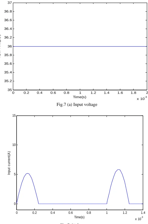
The resonant inverting step-down DC-DC converter was simulated Fig.6 with the following specifications: Input voltage = 36V, Output voltage = -12V, resonant inductor = 0.55mH, resonant capacitor = 45µF, C= 960µF. The output voltage is step-down with negative polarity to that of the input voltage.
Fig 6. Simulation circuit for resonant inverting step-down DC-DC converter
0 0.2 0.4 0.6 0.8 1 1.2 1.4 1.6 1.8 2
x 10-3
35 35.2 35.4 35.6 35.8 36 36.2 36.4 36.6 36.8 37
Time(s)
In
p
ut
V
o
lt
ag
e(
v
)
Fig.7 (a) Input voltage
0 0.2 0.4 0.6 0.8 1 1.2 1.4
x 10-3
0 5 10 15
Time(s)
Input
c
ur
rent
(A
)
0 0.2 0.4 0.6 0.8 1 1.2 1.4 1.6
x 10-3 0 5 10 15 20 Time(s) S w it c h c u rre n t (I 2 )A
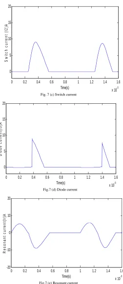
Fig. 7 (c) Switch current
0 0.2 0.4 0.6 0.8 1 1.2 1.4 1.6
x 10-3 0 5 10 15 20 Time(s) D io de c ur ren t( I3) A
Fig.7 (d) Diode current
0 0.2 0.4 0.6 0.8 1 1.2 1.4 1.6
x 10-3 -20 -10 0 10 20 Time(s) R e s onant c ur ren t( Ir )A
0 0.2 0.4 0.6 0.8 1 1.2 1.4 1.6 1.8
x 10-3 -20
0 20 40 60 80 100
Time(s)
R
es
o
nant
v
ol
tag
e(
V
r)
V
Fig.7 (f) Resonant voltage
Fig.7 (g) Switching pulses
Fig.7 (a-g) Simulation results of the resonant inverting step-down DC-DC converter.
7. Conclusion
A step-up based resonant converter with Switching Capacitor Technique and Resonant inverting Step-down DC-DC converter is presented. Both model has implemented with resonant technique of zero current switching. Both circuits has simulated using MATLAB/Simulink tool. Waveforms related to the circuits are presented. It is observed that the reduction in switching losses, Electromagnetic Interference and increased voltage gain are verified. High efficiency can then be obtained.
References
[1] YeungY.P.B., Cheng K.W.E., Sutanto D., HO S.L.: ‘Zero-current switching switched-capacitor quasi resonant step-down converter’, IEE Proc., Electr. Power Appl., 2002, 149, (2), pp. 111–121
[2] K.W.E.Chengand P.D.Evans, “Parallel-mode extended-period quasi resonant converter,” Proc. Inst. Elect. Eng., pt. B, vol. 138, no. 5, pp. 243–251, Sept. 1991.
[3] “Unified theory of extended-period quasiresonant converters,”Proc. IEE—Elect. Power Applicat., vol. 147, no. 2, pp. 119–130, Mar. 2000.
[4] H. Bengtsson, “A switch in methods,” New Electron., pp. 40–41, Aug 1997.
[5] O. C. Mak, Y. C. Wong, and A. Ioinovici, “Step-up DC power supply based on a switched-capacitor circuit,” IEEE Trans. Ind. Electron., vol. 42, pp. 90–97, Feb. 1995.
[7] Yeung Y.P.B., Cheng K.W.E., Sutanto D.: ‘Multiple and fractional voltage conversion ratios for switched-capacitor resonant converters’. Proc. IEEE PESC, 32nd Annual Meeting, 2001, (3), pp. 1289–1294
[8] YeungY.P.B., Cheng K.W.E., Ho S.L., Law K.K.,Sutanto D.: ‘Unified analysis of switched-capacitor resonant converters’, IEEE Trans. Ind. Electron., 2004, 51, (4), pp. 864–873.