ISSN (Online): 2320-9364, ISSN (Print): 2320-9356
www.ijres.org Volume 3 Issue 3 ǁ March 2015 ǁ PP.25-29
Strength Analysis and Optimization Design about the key parts of
the Robot
NIU Dong-Ke
1
JIN Xiao-Yi
1, LU Qiu-Hong
21. Shanghai University of Engineering Science,Shanghai 201620 2. HRSTEK Co., Ltd .Shanghai,Shanghai 201620
ABSTRACT
: Study on structure optimization design about Flip Arms of Mobile Robot. First conducted preliminary structural design, and established finite element analysis model by HYPERMESH, use ANSYSsoftware to study Flip Arms Stress distribution and structure optimization. Strength check to ensure the strength
and stiffness of Flip Arms meet safety requirements, and make sure the reliability of the design, to provide a
theoretical basis for the structural optimization design of Flip Arms. Optimization design considering the
weighted compliance as the object function, the frame was improved by modifying the parameters which are
most sensitive to the character of the frame structure. The results showed that structural optimization design
without affecting the reliability of Flip Arms, reducing the quality of the parts improved and the Flip Arms
flexible mobility, to provide a theoretical basis for the structural design of robot.
Key words
-Mobile robot, Flip Arms, HYPERMESH, ANSYS, Strength Analysis, Optimization DesignI.
INTRODUCTION
Wheel-Track robot has both the advantage of wheeled robot and tracked robot, which as an important object of study by institute and colleges and universities. With the rapid development of intelligent, some extent, wheel-track robot has been widely applied in the investigation, inspection, alert, fire-fighting and other dangerous and harsh environments. According to many complicated work environment, must require the robot working stable enough, so the robot structure design should have higher requirements. In order to meet the performance requirements of the robot enough, all parts robot design is very important. Take the flip arms of the wheel-track robot as the research object, using PROE for three-dimensional modeling, and meshing use the Hypermesh establishment of finite element model, then put the finite element model into ANSYS for strength analysis. Finally, the optimized design and obtains a set of effective method which can make sure the part strength, provide an effective theoretical basis for the structure optimization of robot.
II.
THE BASIC THEORY OF STRUCTURAL OPTIMIZATION
Optimal design function contains design variables, objective function and constraint conditions. Optimization mathematical model defined as:min 1 2
( )
( ,
,
,
n)
f X
f x x
x
(1) whereg( )
0
1,
,
( )
0
1,
,
1,
,
k h
L U
i i i
X
j
m
h X
k
m
X
X
X
i
n
where
X
is design variables,f X
( )
is objective function,g( )
X
、h X
( )
are constraint conditions。 The finite element equation of the parts of the structure is given as:[ ]{ } { }
K
S
F
(2)where,
[ ]
K
is Stiffness matrix;{ }
S
is Element node displacement vector;
{ }
F
is Element node load。1
[ ]
{ }
[ ]
[ ]
{ }
S
F
K
K
S
X
X
X
(3)
Concomitant variable
E
is introduced when topology optimization. where[ ]{ } { }
K
E
Q
(4) Therefore, the response sensitivity of the parts is given as:{ }
[ ]
{ } { }
{ }
T
T
g
Q
F
K
S
E
S
X
X
X
X
(5)
III. THE STRENGTH ANALYSIS
3.1 DescriptionThe flip arms of Wheel-Track robot used to connect driving wheel and deflection roller is shown in figure1.It is the key components ensure deflection roller movement accurate and flexible[1-2].In order to ensure its accuracy and reliability during exercise, we need to know the amount of deformation and the maximum stress when it’s working, and compared with the material characteristics, we can get the safety factor. Then using the finite element analysis software to get the simulation model and calculated[3].
Figure1: Parts location diagram
3.2 Model simplification
Different analysis purposes need different requirements for CAD model. To build the finite element models, If only pay attention to the overall structure, it can be to remove fine characteristic structure. For example, to analyze the whole structure mode, can remove small fillet, radius and bolt etc…There are many small threaded holes and radius in the flip arms, this threaded holes and radius will affect generating the high quality grid and affect the accuracy of finite element calculation. And these threaded holes and radius on the whole model has little impact, considering the force of flip arms and the accuracy of the flip arms model calculation results, small threaded holes and radius removed[4]. The position of these threaded holes and radius which should be removed
is shown in Figure 2. Comparing with the original model and the simplified model is shown in Figure 3。
Figure2: Eliminates screw Figure3: Rotating Arms Figure4: The finite holes and radius before and after simplify element mesh model
3.3 Finite element analysis
Material parameters: This part use the Type 45 steel,material characteristics as shown in Table 1。 Table 1.Material properties
Material
Elastic Modulus
(EX)
Poisson's ratio
(PRXY)
Yield limit
(
s)Shear Strength
(
)Type 45
The simplify model will be imported into the HYPERMESH, and the finite element mesh model is established[5]. Considering the minimum geometry of the model and the grid number, the average mesh size is set to 2mm, choice of 8-node hexahedral elements SOLID185, got 7887 nodes and 107412 units. The finite element mesh model is shown in Figure 4.According to the known constraints and load conditions, to add constraint and load imposed on the corresponding position of the finite element mesh model.
Figure5: Condition 1 Figure6: Condition 2
Condition 1 (Figure5): Obstacle crossing and flip arm 35- degrees angle with the ground.
The critical point: The motor is connected with the flip arm through the gear shaft, output torque Tc; The small end of the flip arm
degrees angle with the step, in a critical condition. Where the end of flip arm exerts a downward force and the front driving wheel is lifted, the front driving effect on the ground without the force. The boundary conditions can be divided into three parts:1)Six bolt holes. The stress can be decomposed into downward radial force and tangential force.
Radial force:
F
r
(
G
/ 4) / 6 sin
Tangential force:
F
(
G
/ 4) / 6 cos
2) The clockwise direction torque of the driving wheel:
* * / 2
Tc
T i n
3) Fixed constraint: According to the position of flip arm in the assembly and condition 1, and applying a full constraint except axial rotation to the threaded hole of deflection roller, applying axial constraint in the position of between driving wheel and flip arm, applying axial rotation constraint in the position of between deflection roller and flip arm.
Where: G=2500N.
35
o.T
1160
Nmm
。i
250
。n
0.73
。Calculated:
F
85.33 N
.F
r
59.75
N
。Tc
105850
Nmm
Condition 2 (Figure6): Since propped state
Description: Refers to flip arm propped itself under the action of the drive motor, the angle between flip
arm and horizontal direction of
. The boundary conditions can be divided into four parts applied:1) The clockwise direction torque of the driving wheel:
* * / 2
Tc
T i n
The great circle wall and center auxiliary nodes components of a flexible connection RBE3, and the torque applied in RBE3.
2) Six bolt holes. The stress can be decomposed into downward radial force and tangential force.
Radial force:
F
r
(
G
/ 4) / 6 sin
Tangential force:
F
(
G
/ 4) / 6 cos
4)Bolt holes on the deflection roller. The stress can be decomposed into upward radial force and tangential force.
Radial force:
F
r'
(
G
/ 4) / 2 sin
Tangential force:
F
'
(
G
/ 4) / 2 cos
5)Fixed constraint: Applying a full constraint to the threaded hole of deflection roller, applying axial constraint in the position of between driving wheel and flip arm, apply axial rotation constraint in the position of between deflection roller and flip arm.
Calculated:
Tc
105850
Nmm
,F
r
14.50
N
,F
103.15 N
,F
r'
43.49
N
,F
'
309.46 N
.3.4 The results of finite element analysis
The finite element model was established and solved according to the known conditions for each kind of condition[6]. Calculation results are as follows:
The deformation image and stress image of finite element model of condition1 is shown in Figure 7. Obviously, the maximum deformation of the components for the 0.136627mm and distribution in the model of the larger end, the maximum stress is 72.5985MPa and distribution in the connecting screw hole near the guide wheel, the maximum shear stress is 41.8228MPa and distribution in the bolt hole of the guide wheel.
Figure7: Results image of Condition 1 Figure8: Results image of Condition 2
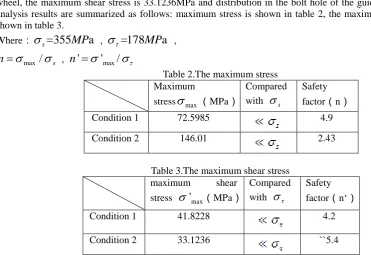
The deformation image and stress image of finite element model of condition2 is shown in Figure 8. Obviously, the maximum deformation of the components for the 0.265382mm and distribution in the model of the larger end, the maximum stress is 146.01MPa and distribution in the connecting screw hole near the guide wheel, the maximum shear stress is 33.1236MPa and distribution in the bolt hole of the guide wheel. ANSYS analysis results are summarized as follows: maximum stress is shown in table 2, the maximum shear stress is shown in table 3.
Where:
s=355
MP
a
,
=178
MP
a
,max
/
sn
,n
'
'
max/
Table 2.The maximum stress Maximum
stress
max(MPa)Compared
with
sSafety
factor(n)
Condition 1 72.5985 4.9
Condition 2 146.01 2.43
Table 3.The maximum shear stress maximum shear
stress
'
max(MPa)Compared
with
Safety
factor(n‘)
Condition 1 41.8228 4.2
Condition 2 33.1236 ``5.4
In conclusion: In two conditions, the flip arm of maximum stress and maximum shear stress are far less than the material yield limit and material shear modulus, safety factor is big enough[7-8]. Therefore, the flip arm is safe and stable work in the two conditions, meet the design requirements.
IV. STRUCTURE OPTIMIZATION DESIGN
area, the relative density of the design area as the design variables .Objective function is the countdown for structural stiffness, when the load is given, stiffness values become large and the objective function value will be smaller and vice versa[9].
According to the two conditions for topology optimization, the volume fraction after many iterative calculations results of convergence. After optimize it can be seen a reasonable distribution of the material and the load transfer path, evident part structure is simplified to reduce the number of quality is shown in Figure 9 and Figure 10.
Figure9: The optimization results image Figure10: Flip Arm model after optimization
V.
IN CONCLUSION
Firstly, through strength analysis of flip arm in different conditions, the designed structure and materials of flip arm can meet the accuracy, reliability in work demand, strain and stress in the reliable range. In general, flip arm by more vigorous role in threaded hole that on the guide wheel, but less than the allowable stress, other parts of the stress is smaller. Therefore, the flip arm strength, stiffness can meet the safety requirements, through the joint simulation of HYPERMESH and ANSYS, which provides an important basis for the optimization of the structure of parts[10]. Based on reliability the model for the topological optimization and the optimum design of parts, by optimizing the flip arm structure is simplify, reduce the quality of many and achieve the optimization goal, to provide theoretical basis and technical support for the overall structure design of the robot.
REFERENCES
[1] A.Garg,B.Qwen,D.Beller,etal. A Biomechanical and Ergonomic Evaluation of Patient Transferring Task: Bed to Wheelchair and Wheelchair to Bed. Ergonomics, 1991, 3(34):289~312.
[2] Krebshi,Palazzolo JJ. Rehabilitation robotics: performance-based progressive robot-assisted therapy. Autonomous Robots,
2003,(15):7~20.
[3] Rithalla S V , Gonsal K M. Assessment of alternating aim mattresses using a time based interface pressure times hold technique
[J]:1998,35(2):225-230.
[4] Goemka P K,Booker J F .Spherical Bearing :Static and Dynamic Analysis Via the Finite Element method [J].Journalof
Lubrication Technology, Transactions of the ASME,1980,102(3):308-319.
[5] Li Rui.Study on the Attitude Detection and Control System of Mobile Robot with Muti-tracked based on Parallel
Mechanisms[D]. the master's degree thesis of Dong Hua University.2008
[6] CHEN Min,MAO Li-min. Research on the Obstacle Negotiating Performance of Position Changing-Four Tracked Feet-Robot
Mobile Mechanism[P]. Journal of Dong Hua University. Vol. 31,No. 3 Jun. 2005
[7] Chen C X, Trivedi M M. Reactive locomotion control of articulated-tracked mobile robots for obstacle
negotiation[C]//IEEE/RSJ International Conference on Intelligent Robots and Systems. Piscataway, NJ, USA: IEEE, 1993:
1349-1356.
[8] Zheng, J.M.,Chan, K.W.,Gibson, S., Virtual reality, Potential, IEEE, 1998, 17(2):20 ~23
[9] Turner M.L. ,Findley, et al. Development and Testing of a Telemanipulation System with Arm and Hand Motion [C], ASME
IMECE Symposium on Haptic Interfaces,2000.
[10] Yang Tingli,LIU Anxin,LUO Yufeng. Theory and Application of Robot Mechanism Topology [M],Beijing:Science Press,